EP0111780A2 - Dispositif pour le transport de munitions à partir d'un magasin à tambour vers un canon - Google Patents
Dispositif pour le transport de munitions à partir d'un magasin à tambour vers un canon Download PDFInfo
- Publication number
- EP0111780A2 EP0111780A2 EP83111886A EP83111886A EP0111780A2 EP 0111780 A2 EP0111780 A2 EP 0111780A2 EP 83111886 A EP83111886 A EP 83111886A EP 83111886 A EP83111886 A EP 83111886A EP 0111780 A2 EP0111780 A2 EP 0111780A2
- Authority
- EP
- European Patent Office
- Prior art keywords
- cartridges
- drum magazine
- conveyor
- conveyor device
- row
- Prior art date
- Legal status (The legal status is an assumption and is not a legal conclusion. Google has not performed a legal analysis and makes no representation as to the accuracy of the status listed.)
- Granted
Links
Images



Classifications
-
- F—MECHANICAL ENGINEERING; LIGHTING; HEATING; WEAPONS; BLASTING
- F41—WEAPONS
- F41A—FUNCTIONAL FEATURES OR DETAILS COMMON TO BOTH SMALLARMS AND ORDNANCE, e.g. CANNONS; MOUNTINGS FOR SMALLARMS OR ORDNANCE
- F41A9/00—Feeding or loading of ammunition; Magazines; Guiding means for the extracting of cartridges
- F41A9/61—Magazines
- F41A9/64—Magazines for unbelted ammunition
-
- F—MECHANICAL ENGINEERING; LIGHTING; HEATING; WEAPONS; BLASTING
- F41—WEAPONS
- F41A—FUNCTIONAL FEATURES OR DETAILS COMMON TO BOTH SMALLARMS AND ORDNANCE, e.g. CANNONS; MOUNTINGS FOR SMALLARMS OR ORDNANCE
- F41A9/00—Feeding or loading of ammunition; Magazines; Guiding means for the extracting of cartridges
- F41A9/61—Magazines
- F41A9/64—Magazines for unbelted ammunition
- F41A9/73—Drum magazines
- F41A9/74—Drum magazines with radially disposed cartridges
-
- F—MECHANICAL ENGINEERING; LIGHTING; HEATING; WEAPONS; BLASTING
- F41—WEAPONS
- F41A—FUNCTIONAL FEATURES OR DETAILS COMMON TO BOTH SMALLARMS AND ORDNANCE, e.g. CANNONS; MOUNTINGS FOR SMALLARMS OR ORDNANCE
- F41A9/00—Feeding or loading of ammunition; Magazines; Guiding means for the extracting of cartridges
- F41A9/61—Magazines
- F41A9/64—Magazines for unbelted ammunition
- F41A9/76—Magazines having an endless-chain conveyor
-
- F—MECHANICAL ENGINEERING; LIGHTING; HEATING; WEAPONS; BLASTING
- F41—WEAPONS
- F41A—FUNCTIONAL FEATURES OR DETAILS COMMON TO BOTH SMALLARMS AND ORDNANCE, e.g. CANNONS; MOUNTINGS FOR SMALLARMS OR ORDNANCE
- F41A9/00—Feeding or loading of ammunition; Magazines; Guiding means for the extracting of cartridges
- F41A9/61—Magazines
- F41A9/64—Magazines for unbelted ammunition
- F41A9/77—Magazines having a screw conveyor
Definitions
- the invention relates to a conveyor device for feeding cartridges to a firearm from a drum magazine, which is divided into a number of sectors, in each of which there is a row of cartridges, with a first conveyor device which pushes the rows of cartridges out of the sectors of the drum magazine and with one second conveyor for transporting the cartridges pushed out of the sectors to the firearm.
- the first conveyor device consists of an encircling, endless chain provided with drivers, which is in drive connection with the rotating drum magazine. From this first conveying device, the cartridges pass into a second conveying device, which is in drive connection with it, and consists of a conveyor disk, which in turn conveys the cartridges into the weapon.
- the object that is to be achieved with the present invention is to create a conveyor device which ensures reliable transport of the cartridges from the drum magazine to the firearm even at high cadences.
- the transfer of the cartridges from the first conveyor to the second conveyor should function reliably without cartridges falling into the already empty sectors of the drum magazine.
- no great acceleration forces should occur when a row of cartridges is pushed out of a sector.
- no great acceleration forces should occur when the cartridges are transferred from the first conveyor to the second conveyor.
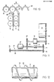
- the device with which this object is achieved is characterized in that a backstop is arranged between the two conveying devices and that the first conveying device has a screw conveyor, the first turn of which has a smaller pitch than the other turns.
- the cartridges 11 are fed from a drum magazine 10 via a conveyor channel 12 to a firearm 13.
- the firearm 13 is shown in Fig.l in three different elevation positions. In the middle position, the gun barrels 14 of the firearm 13 are directed horizontally. From this position, the weapon 13 can be lowered on the one hand until the weapon barrels are inclined downward by approximately 10-15 °, and on the other hand the weapon can be raised by approximately 90 ° until the weapon barrels 14 project approximately into the zenith.
- the downwardly inclined weapon barrels 14 are designated by the reference number 14a and the weapon barrels 14 projecting into the zenith are designated by the reference number 14b.
- FIG. 2 there is a so-called disk channel 15 between the delivery channel 12 and the weapon 13, which allows an elevation of the firearm 13 by approximately 90 °.
- the cartridges 11 pass from the drum magazine 10 onto an endless conveyor chain 16.
- This conveyor chain 16 is guided around a chain wheel 17 at one end of the conveyor channel.
- another sprocket not shown, for deflecting the conveyor chain 16.
- the conveyor chain 16 is guided through the disk channel 15. Deflection rollers 18 for the conveyor chain 16 are provided at the entrance to the disk channel 15.
- FIG. 3 shows two rows of cartridges 19 and 20 located in the drum magazine 10.
- the row of cartridges 19 can be fed to the conveying channel 12 in the position shown with the aid of a conveying device 27 described below. So that the cartridges row 20 of the feed channel 12 can be supplied, must first the drum magazine around its axis 21 10 - be rotated 180 °.
- the firearm 13 has six gun barrels 14 which rotate about their common axis 22 in a series fire.
- a drum magazine 10 has thirty sectors 23, of which only the center lines are indicated. Each sector 23 contains a row of twenty-five cartridges 11. In FIG. 1 only two first cartridges 11 of a row are shown.
- the drum magazine 10 is located in a cylindrical housing 24 (FIGS. 5 and 6), of which only the front, disk-shaped end wall 25 is visible in FIG.
- the end wall 25 has an opening 26 through which cartridges 11 can be removed from the drum magazine 10.
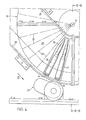
- a row of cartridges 19, 20 after the other is pushed out of the drum magazine 10 through the opening 13 by a conveyor device 27, which is described further below. While a row of cartridges 19 is pushed out of the drum magazine 10, this rotates Drum magazine 10 continuously by one division, ie position A of drum magazine 10 comes to position B.
- drum magazine 10 rotates a division, whereby the cartridge 11 moves from point A to point B.
- the cartridges 11 ejected from the drum magazine 10 pass through the conveyor channel 12, which is indicated in FIG. 4 by two walls 28, 29, to the firearm 13.
- this conveyor channel 12 there is a second conveyor device 30a, which is described further below.
- the direction of movement of the cartridges 11 resulting from the rotation of the drum magazine 10 in the direction of the arrow D and the axial displacement of the cartridge row 19 coincides with the conveying direction of the conveyor device 27, ie the axis of this conveyor device 27 is inclined so that its direction matches this resulting direction of movement coincides, as can be clearly seen from FIG.
- a backstop in front of the opening 26 described further below prevents the cartridges 11 ejected from the drum magazine 10 by the conveying device 27 from falling back through the opening 26.
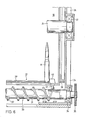
- the conveyor device 27 has a screw conveyor 30.
- the screw conveyor 30 consists of a cylindrical body 31 to which a helical rib 32 is attached.
- the two ends of the screw conveyor 30 are held in bearings 33 (FIG. 5) and 34 (FIG. 6) in the housing 24 of the drum magazine 10.
- To drive the screw conveyor 30 is a gear 35, which is attached to one end of the screw conveyor 30.
- the gear 35 is driven by a hydraulic motor, as described below.
- the drum magazine 10 contains a drum axis 21.
- the two ends of the drum axis 21 are held in bearings 36 (Fig.5) and 37 (Fig.6) in the housing 24 of the drum magazine 10.
- a gear 38 which is attached to an end face of the drum magazine 10 and is driven by the aforementioned electric motor, as described below.
- Each row of cartridges 19, 20 is held in the drum magazine 10 so as to be displaceable in an axially directed rail 39.
- the first cartridge 11 of such a cartridge row 19 is shown in FIG. 5 and the last cartridge 11 in FIG.
- a driver 40 is displaceable, which has a bolt 41.
- the bolt 41 is in engagement with the helical rib 32 of the screw conveyor 30.
- the driver 40 moves from its right end position according to FIG. 6 into its left end position according to FIG. 5 and thereby pushes a series of twenty-five cartridges 11 out of the drum magazine 10.
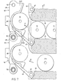
- the mentioned conveyor channel 12 with the walls 28 and 29 there is an endless conveyor chain 16, which consists of individual chain links 42, see also FIG. 7.
- Each chain link 42 has a T-shaped extension 43, which is located in a Cross section of C-shaped rail 44 or 45 is performed.
- the chain links 42 with the cartridges 11 move from the drum magazine 10 to the firearm 13 in the left rail 44 and the empty chain links 42 return from the firearm 13 to the drum magazine 10 in the adjacent rail 45.
- each chain link 42 has a shell 48 which serves to receive a cartridge 11.
- a carrier 49 is fastened to this shell 48, one end of which divides like a fork. Bores 50 and 51 are provided at both ends of the carrier 49.
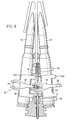
- the upper chain wheel 54 has five cutouts 57, in which the joints 58 of an endless conveyor chain 66 engage.
- a lower sprocket 53 is configured in the same way as the upper sprocket 54.
- Carriers 59 are fastened to the endless chain 66, which are arranged at equal distances from one another and which have the task of removing the cartridges 11 from the sectors 23 of the drum magazine 10 push out.
- the cartridges 11 pushed out of the drum magazine 10 are fed to a second conveyor chain 60.
- This second conveyor chain 60 moves in the direction of arrow B over the drum magazine 10 and brings the cartridges 11 to the firearm 13.
- the endless conveyor chain 66 moves in the direction of arrow A and the drum magazine 10 rotates in the direction of arrow C (FIG. 9).
- a slide 61 is located below the second conveyor chain 60 and above the cartridges 11 arranged in the drum magazine 10.
- This slide 61 has a passage opening 62 and a deflection nose 63, which ensures that the cartridges 11 fit exactly into the individual receiving cups 64 of the second conveyor chain 60.
- This slide 61 is moved back and forth in the direction of the double arrow D by a cam disk or eccentric disk, not shown. As soon as the last cartridge 11a of a row of cartridges is located in the second conveyor chain 60, the slide 61 is shifted to the left in the direction of the arrow B in FIG.
- the driver 59 also migrates while it is pushing a row of cartridges out of the drum magazine 10, ie while it is moving from its lower position 59a to its upper position 59b, thanks to the inclined position of the conveyor chain 66 in the direction of arrow C. right in Fig. 9.
- the inclination of the endless conveyor chain 66 with respect to a vertical is selected so that the driver 59 moves at the same speed in the direction of arrow C as the drum magazine 10.
- the driver 59 remains constantly in engagement with the lower one during its upward movement Most cartridge 11c in a row in a sector 23.
- the driver 59 is shaped such that it touches the last cartridge 11a in a row until it is completely inserted into a receiving cup 64 of the second conveyor chain 60. As a result, each free flight of a cartridge 11 is avoided when entering the conveyor chain 60.
- the slide 61 (FIG. 9) is replaced by pivotable flaps 65.
- These flaps 65 are hinged to partition walls 76 of the drum magazine 10, are opened and closed by a device, not shown. 10, this conveyor chain 60 moves in the direction of arrow B to the left. Accordingly, the flaps 65 according to FIG. 10 are opened by the cartridges 11 in the counterclockwise direction.
- the drum magazine 11 is used to drive the drum magazine 10, a hydraulic motor 67, which drives it via gears 68 and 69, a reduction gear 70 and the gears 71 and 38 (FIG. 6). Furthermore, the conveyor screw 30 of the first conveyor device 27 is driven by the motor 67 via a clutch 72 and the gear wheels 73 and 35 (FIG. 6). The second conveyor device 30a (FIG. 2) is driven in a manner not shown via a further gear wheel 74 attached to the screw conveyor 30.
- the gear ratio of the gear transmission shown in Fig.ll must of course be chosen so that all cartridge rows 19, 20 are ejected by the conveyor 27 when the drum magazine rotates.
Landscapes
- Engineering & Computer Science (AREA)
- General Engineering & Computer Science (AREA)
- Manufacturing Of Cigar And Cigarette Tobacco (AREA)
- Specific Conveyance Elements (AREA)
- Earth Drilling (AREA)
Applications Claiming Priority (2)
| Application Number | Priority Date | Filing Date | Title |
|---|---|---|---|
| CH747482 | 1982-12-22 | ||
| CH7474/82 | 1982-12-22 |
Publications (3)
| Publication Number | Publication Date |
|---|---|
| EP0111780A2 true EP0111780A2 (fr) | 1984-06-27 |
| EP0111780A3 EP0111780A3 (en) | 1985-09-25 |
| EP0111780B1 EP0111780B1 (fr) | 1988-01-20 |
Family
ID=4325685
Family Applications (1)
| Application Number | Title | Priority Date | Filing Date |
|---|---|---|---|
| EP83111886A Expired EP0111780B1 (fr) | 1982-12-22 | 1983-11-28 | Dispositif pour le transport de munitions à partir d'un magasin à tambour vers un canon |
Country Status (7)
| Country | Link |
|---|---|
| US (1) | US4589325A (fr) |
| EP (1) | EP0111780B1 (fr) |
| JP (1) | JPS59119198A (fr) |
| BR (1) | BR8307051A (fr) |
| DE (1) | DE3375429D1 (fr) |
| ES (1) | ES8501113A1 (fr) |
| IL (1) | IL70386A (fr) |
Cited By (1)
| Publication number | Priority date | Publication date | Assignee | Title |
|---|---|---|---|---|
| EP0233347A1 (fr) * | 1986-02-04 | 1987-08-26 | Werkzeugmaschinenfabrik Oerlikon-Bührle AG | Dispositif d'alimentation en cartouches d'une arme à feu hors d'un chargeur à tambour |
Families Citing this family (3)
| Publication number | Priority date | Publication date | Assignee | Title |
|---|---|---|---|---|
| US4882971A (en) * | 1988-05-27 | 1989-11-28 | Teleflex, Incorporated | Linkless ammunition transporter |
| US5218162A (en) * | 1992-01-21 | 1993-06-08 | General Electric Co. | Double-ended ammunition handling system for rapid-fire guns |
| DE102020104465B3 (de) * | 2020-02-20 | 2021-07-29 | Krauss-Maffei Wegmann Gmbh & Co. Kg | Magazin |
Family Cites Families (17)
| Publication number | Priority date | Publication date | Assignee | Title |
|---|---|---|---|---|
| FR833617A (fr) * | 1937-06-25 | 1938-10-26 | Appareil servant à lancer dans l'atmosphère, à partir d'une certaine hauteur, desobjets divers | |
| US2284286A (en) * | 1939-08-08 | 1942-05-26 | Bliss E W Co | Container handling apparatus |
| FR956038A (fr) * | 1946-11-27 | 1950-01-23 | ||
| LU30583A1 (fr) * | 1951-02-17 | 1952-08-18 | Brevets Aero-Mecaniques S.A. | Perfectionnements apportes aux chargeurs a cartouches pour armes automatiques, notamment a ceux pour armes a cadence de tir elevee |
| US2854125A (en) * | 1955-02-28 | 1958-09-30 | Corn Prod Refining Co | Container transferring means |
| BE550282A (fr) * | 1955-08-16 | |||
| US2935914A (en) * | 1957-08-05 | 1960-05-10 | Darsie Burns | Linkless feed system for guns |
| CH379969A (de) * | 1959-02-13 | 1964-07-15 | Oerlikon Buehrle Ag | Munitionsmagazin für automatische Feuerwaffen |
| US2993415A (en) * | 1959-07-10 | 1961-07-25 | Elio W Panicci | Combined continuous linkless supplier and cartridge feed mechanism for automatic guns |
| US3437005A (en) * | 1967-05-25 | 1969-04-08 | Gen Electric | Flexible article conveyor for high speed applications |
| DE2024672C2 (de) * | 1969-05-22 | 1982-04-29 | General Electric Co., Schenectady, N.Y. | Magazin für lose Munition mit einem Zuführsystem |
| US3683743A (en) * | 1969-08-01 | 1972-08-15 | Stoner Eugen Morrison | Linkless cartridge feed system |
| US3696704A (en) * | 1971-05-13 | 1972-10-10 | Gen Electric | Ammunition bulk loader |
| GB1461481A (en) * | 1973-04-17 | 1977-01-13 | Gen Electric | Helical assemblies and article handling devices using such assemblies |
| US3881395A (en) * | 1973-07-17 | 1975-05-06 | Gen Electric | Article handling system |
| US4393746A (en) * | 1981-07-31 | 1983-07-19 | The United States Of America As Represented By The Secretay Of The Army | Ammunition magazine with built-in compartment covers |
| US4492144A (en) * | 1982-04-05 | 1985-01-08 | General Electric Company | Transport mechanism for ammunition |
-
1983
- 1983-11-28 EP EP83111886A patent/EP0111780B1/fr not_active Expired
- 1983-11-28 DE DE8383111886T patent/DE3375429D1/de not_active Expired
- 1983-12-05 IL IL70386A patent/IL70386A/xx unknown
- 1983-12-12 US US06/560,373 patent/US4589325A/en not_active Expired - Fee Related
- 1983-12-21 JP JP58239962A patent/JPS59119198A/ja active Pending
- 1983-12-21 ES ES528251A patent/ES8501113A1/es not_active Expired
- 1983-12-21 BR BR8307051A patent/BR8307051A/pt not_active IP Right Cessation
Cited By (2)
| Publication number | Priority date | Publication date | Assignee | Title |
|---|---|---|---|---|
| EP0233347A1 (fr) * | 1986-02-04 | 1987-08-26 | Werkzeugmaschinenfabrik Oerlikon-Bührle AG | Dispositif d'alimentation en cartouches d'une arme à feu hors d'un chargeur à tambour |
| US4742756A (en) * | 1986-02-04 | 1988-05-10 | Werkzeugmaschinenfabrik Oerlikon-Buhrle Ag | Apparatus for feeding cartridges from a drum magazine to a firing weapon |
Also Published As
| Publication number | Publication date |
|---|---|
| EP0111780B1 (fr) | 1988-01-20 |
| US4589325A (en) | 1986-05-20 |
| ES528251A0 (es) | 1984-11-01 |
| JPS59119198A (ja) | 1984-07-10 |
| BR8307051A (pt) | 1984-07-31 |
| ES8501113A1 (es) | 1984-11-01 |
| DE3375429D1 (en) | 1988-02-25 |
| EP0111780A3 (en) | 1985-09-25 |
| IL70386A (en) | 1988-06-30 |
Similar Documents
| Publication | Publication Date | Title |
|---|---|---|
| DE2839839C3 (de) | Patronenzuführvorrichtung für automatische Feuerwaffen | |
| DE68909473T2 (de) | Munitionsmagazin mit Fördereinrichtung. | |
| EP0231493B1 (fr) | Transporteur à maillons pour l'alimentation en cartouches d'une arme à feu automatique | |
| DE2632207A1 (de) | Selbsttaetige feuerwaffe mit mindestens zwei patronenmagazinen | |
| DE3702603A1 (de) | Ladesystem fuer patronierte munition enthaltende container | |
| EP0290031B1 (fr) | Mécanisme alimentateur de munition à partir d'un conteneur vers une arme à feu automatique | |
| EP0450297B1 (fr) | Dispositif d'alimentation en cartouches | |
| CH657914A5 (de) | Zufuehreinrichtung mit seitlicher abstreifung fuer gegurtete patronenmunition, insbesondere fuer eine maschinenkanone vom gatling-typ. | |
| EP0111780B1 (fr) | Dispositif pour le transport de munitions à partir d'un magasin à tambour vers un canon | |
| DE69223485T2 (de) | Munitionsmagazin, insbesondere für Kampfpanzer | |
| DE3040798C2 (fr) | ||
| EP0529289B1 (fr) | Dispositif d'alimentation d'un canon du type gatling avec deux types de munition différentes | |
| EP0233347B1 (fr) | Dispositif d'alimentation en cartouches d'une arme à feu hors d'un chargeur à tambour | |
| EP0458106B1 (fr) | Dispositif d'alimentation en cartouches pour une arme à feu | |
| EP0184008B1 (fr) | Dispositif de surveillance de mise à feu à retardement pour canon à moteur externe | |
| CH657698A5 (de) | Maschinenkanone vom gatling-typ. | |
| DE3812696A1 (de) | Vorrichtung zur munitionszufuehrung | |
| DE3342223C2 (de) | Patronenzuführvorrichtung | |
| EP0525373B1 (fr) | Dispositif d'alimentation de deux types de munitions différentes à un Gatling | |
| DE3202840A1 (de) | Kanone nach dem prinzip der gatling-gun | |
| DE2024672C2 (de) | Magazin für lose Munition mit einem Zuführsystem | |
| EP0279048B1 (fr) | Appareil pour alimenter une arme de munitions provenant d'un magasin | |
| EP0403776A1 (fr) | Magasin à cartouches et dispositif de chargement en cartouches | |
| DE4140843C1 (en) | Light machine gun with multi-shaft cartridge magazine - has magazine shafts sepd. by partitions,with cartridges transverse to firing direction | |
| DE68909536T2 (de) | Vorrichtung zum Handhaben von Munition. |
Legal Events
| Date | Code | Title | Description |
|---|---|---|---|
| PUAI | Public reference made under article 153(3) epc to a published international application that has entered the european phase |
Free format text: ORIGINAL CODE: 0009012 |
|
| AK | Designated contracting states |
Designated state(s): CH DE FR GB IT LI SE |
|
| PUAL | Search report despatched |
Free format text: ORIGINAL CODE: 0009013 |
|
| AK | Designated contracting states |
Designated state(s): CH DE FR GB IT LI SE |
|
| RHK1 | Main classification (correction) |
Ipc: F41D 10/24 |
|
| 17P | Request for examination filed |
Effective date: 19851014 |
|
| 17Q | First examination report despatched |
Effective date: 19860620 |
|
| R17C | First examination report despatched (corrected) |
Effective date: 19870205 |
|
| GRAA | (expected) grant |
Free format text: ORIGINAL CODE: 0009210 |
|
| AK | Designated contracting states |
Kind code of ref document: B1 Designated state(s): CH DE FR GB IT LI SE |
|
| ITF | It: translation for a ep patent filed | ||
| GBT | Gb: translation of ep patent filed (gb section 77(6)(a)/1977) | ||
| REF | Corresponds to: |
Ref document number: 3375429 Country of ref document: DE Date of ref document: 19880225 |
|
| ET | Fr: translation filed | ||
| PLBE | No opposition filed within time limit |
Free format text: ORIGINAL CODE: 0009261 |
|
| STAA | Information on the status of an ep patent application or granted ep patent |
Free format text: STATUS: NO OPPOSITION FILED WITHIN TIME LIMIT |
|
| 26N | No opposition filed | ||
| PGFP | Annual fee paid to national office [announced via postgrant information from national office to epo] |
Ref country code: FR Payment date: 19901012 Year of fee payment: 8 |
|
| PGFP | Annual fee paid to national office [announced via postgrant information from national office to epo] |
Ref country code: GB Payment date: 19901016 Year of fee payment: 8 |
|
| PGFP | Annual fee paid to national office [announced via postgrant information from national office to epo] |
Ref country code: CH Payment date: 19901018 Year of fee payment: 8 |
|
| PGFP | Annual fee paid to national office [announced via postgrant information from national office to epo] |
Ref country code: SE Payment date: 19901019 Year of fee payment: 8 |
|
| PGFP | Annual fee paid to national office [announced via postgrant information from national office to epo] |
Ref country code: DE Payment date: 19901030 Year of fee payment: 8 |
|
| ITTA | It: last paid annual fee | ||
| PG25 | Lapsed in a contracting state [announced via postgrant information from national office to epo] |
Ref country code: GB Effective date: 19911128 |
|
| PG25 | Lapsed in a contracting state [announced via postgrant information from national office to epo] |
Ref country code: SE Effective date: 19911129 |
|
| PG25 | Lapsed in a contracting state [announced via postgrant information from national office to epo] |
Ref country code: LI Effective date: 19911130 Ref country code: CH Effective date: 19911130 |
|
| GBPC | Gb: european patent ceased through non-payment of renewal fee | ||
| PG25 | Lapsed in a contracting state [announced via postgrant information from national office to epo] |
Ref country code: FR Effective date: 19920731 |
|
| REG | Reference to a national code |
Ref country code: CH Ref legal event code: PL |
|
| PG25 | Lapsed in a contracting state [announced via postgrant information from national office to epo] |
Ref country code: DE Effective date: 19920801 |
|
| REG | Reference to a national code |
Ref country code: FR Ref legal event code: ST |
|
| EUG | Se: european patent has lapsed |
Ref document number: 83111886.4 Effective date: 19920604 |