EP0111992A2 - Dynamisch interaktiv reagierendes Steuerungsgerät und Anlage - Google Patents
Dynamisch interaktiv reagierendes Steuerungsgerät und Anlage Download PDFInfo
- Publication number
- EP0111992A2 EP0111992A2 EP83305283A EP83305283A EP0111992A2 EP 0111992 A2 EP0111992 A2 EP 0111992A2 EP 83305283 A EP83305283 A EP 83305283A EP 83305283 A EP83305283 A EP 83305283A EP 0111992 A2 EP0111992 A2 EP 0111992A2
- Authority
- EP
- European Patent Office
- Prior art keywords
- responsive
- information
- response
- control
- producing
- Prior art date
- Legal status (The legal status is an assumption and is not a legal conclusion. Google has not performed a legal analysis and makes no representation as to the accuracy of the status listed.)
- Granted
Links
Images





Classifications
-
- G—PHYSICS
- G05—CONTROLLING; REGULATING
- G05B—CONTROL OR REGULATING SYSTEMS IN GENERAL; FUNCTIONAL ELEMENTS OF SUCH SYSTEMS; MONITORING OR TESTING ARRANGEMENTS FOR SUCH SYSTEMS OR ELEMENTS
- G05B19/00—Program-control systems
- G05B19/02—Program-control systems electric
- G05B19/04—Program control other than numerical control, i.e. in sequence controllers or logic controllers
- G05B19/10—Program control other than numerical control, i.e. in sequence controllers or logic controllers using selector switches
- G05B19/106—Program control other than numerical control, i.e. in sequence controllers or logic controllers using selector switches for selecting a program, variable or parameter
- G05B19/108—Program control other than numerical control, i.e. in sequence controllers or logic controllers using selector switches for selecting a program, variable or parameter characterised by physical layout of switches; switches co-operating with display; use of switches in a special way
-
- G—PHYSICS
- G05—CONTROLLING; REGULATING
- G05B—CONTROL OR REGULATING SYSTEMS IN GENERAL; FUNCTIONAL ELEMENTS OF SUCH SYSTEMS; MONITORING OR TESTING ARRANGEMENTS FOR SUCH SYSTEMS OR ELEMENTS
- G05B2219/00—Program-control systems
- G05B2219/20—Pc systems
- G05B2219/23—Pc programming
- G05B2219/23053—Knob with tactile feedback, representing clicks, detents programmed
-
- G—PHYSICS
- G05—CONTROLLING; REGULATING
- G05B—CONTROL OR REGULATING SYSTEMS IN GENERAL; FUNCTIONAL ELEMENTS OF SUCH SYSTEMS; MONITORING OR TESTING ARRANGEMENTS FOR SUCH SYSTEMS OR ELEMENTS
- G05B2219/00—Program-control systems
- G05B2219/20—Pc systems
- G05B2219/23—Pc programming
- G05B2219/23379—Knob, delivering pulses, digipot, electronic potentiometer
-
- H—ELECTRICITY
- H01—ELECTRIC ELEMENTS
- H01H—ELECTRIC SWITCHES; RELAYS; SELECTORS; EMERGENCY PROTECTIVE DEVICES
- H01H3/00—Mechanisms for operating contacts
- H01H2003/008—Mechanisms for operating contacts with a haptic or a tactile feedback controlled by electrical means, e.g. a motor or magnetofriction
Definitions
- This invention relates generally to the field of controls and control systems for use with controlled systems or other utilization devices, and more particularly to such controls and control systems wherein an information signal is generated responsive to movement of a moveable element and which movement is productive of an associated interactive tactually perceivable response.
- controllable apparatus or more generally utilization devices have long required the capability to interact with a managing element in connection with the operation performed by the managing element.
- This interfacing capability has required the flow of information in both directions: as status indications from the controllable apparatus or utilization device to the managing element, generally hereinafter referred to as an output operation; and conversely from the managing element to the controllable apparatus, generally hereinafter referred to as an input operation.
- 'input' and 'output' are used with reference to the electrical system.
- the managing element can take numerous forms. Frequently the managing element is a human operator who reacts accordingly to status indications from the controllable apparatus. However managing elements can assume other forms, such as automated systems including electro-mechanically controlled implements for effecting operations with respect to one or more selected parameters of movement.
- "ope-rator” is used to mean any managing element, such as a human operator or electro-mechanically controlled implement or the like, that interacts with the controllable apparatus.
- Such systems of necessity must include an interface between the controllable apparatus and the operator which permits the efficient flow of information in both input and output operations. In the broad area of input operation, this frequently includes a displacement device having a moveable portion with a parameter of movement associated therewith.
- Such parameters of movement can include physical motion of either a translatory or rotational nature, e.g., the translatory or rotational movement of a single or multiple position switch, potentiometer, etc.
- efficient flow of information requires that the information from the controllable apparatus be in a format perceivable by the operator.
- the formatting of such information often involves a plurality of relations involving the visual, auditory or tactile senses.
- Well known devices useful for the flow of output information to the visual senses are-various light indicator devices including light emitting diodes and cathode ray tubes; and to the auditory senses, conventional loud speakers employing permanent magnetics and voice coils, and more recently solid state sounding devices.
- Tactually perceivable sensations have not been used in a dynamically interactive manner.
- the use of the tactile sense has been restricted to a static interaction, for example, for perception of fixed detents and/or a constant drag in devices executing translatory or rotational motion; e.g., rotational devices having a fixed drag or a fixed number of detents for indication of position.
- Such requirements have frequently resulted in multifunctional inputs or output devices, such as switches or knobs whose functions can be changed in a dynamic manner in response to changing requirements, or indicating devices such as cathode ray tubes on which the display thereon can be quickly changed.
- switches or knobs whose functions can be changed in a dynamic manner in response to changing requirements, or indicating devices such as cathode ray tubes on which the display thereon can be quickly changed.
- indicating devices such as cathode ray tubes on which the display thereon can be quickly changed.
- soft e.g., soft switches
- a particular example of multifunctional use of a push button is observed with the so called "soft keys" which are frequently encountered on the typewriter type keyboard generally found with a computer terminal.
- the function of such keyboard keys can be generally assigned to any of a multitude of functions depending upon the particular application; such functions can thereafter be changed as easily as entering new data on the computer terminal.
- a solution to the problem presented by the nature of the output signal produced by a potentiometer is afforded by the use of a tachometer.
- a slotted disc is attached to a rotatable shaft, with a light source positioned on one side of the sloted disc, and a light sensing means positioned on the opposite side of the disc, in alignment with the light source. Consequently, as the shaft is rotated, the beam of the light is interrupted by the rotating disc, thereby producing an output signal, usually of a binary nature.
- decoding means both amount of rotation as well as speed of rotation are ascertainable.
- an input device incorporating a tachometer while being able to provide input information, still suffers from a number of short comings.
- such an input device while being capable of providing information based upon rotational motion, would generally lack end stops, i.e., means to limit the extremeties of angular rotation.
- a positionable device having a moveable portion capable of translating motion directly into an information signal, and which is capable of simultaneous response to status indications from controllable apparatus or operator providing output information to a managing element through the tactile sense.
- the design of such a positionable device with input/output interactive capability incorporating the present invention is extremely flexible, having the major parameters of interest associated with input and output operations being easily and dynamically changeable.
- the tactually perceivable sensations can be provided in functional relation or a random, arbitrary or other desired relation to movement of the moveable portion and which is changeable in response to one or more selected parameters of movement of the moveable portion. One may select among a plurality of such relations in response to any selected input, e.g., status indication.
- the parameters associated with input operations including direction of movement, amount of movement and rate of movement are easily defineable and changed.
- movement of the moveable portion could be associated with either an increase or decrease in value of one or more of the parameters, and the resulting magnitudes of parameter change associated with a given - angular displacement or angular rate of rotation can likewise be easily adjusted or changed.
- tactile parameters associated with output operation including amount of static rotational friction present, as well as the number and location of end stops and detents are easily definable and changeable.
- the amount of static rotational friction can vary both in response to angular position and -direction of rotation.
- the existence and placement of end stops to limit rotation in either direction, as well as the number, placement and force required to by-pass detents is likewise easily definable and changeable.
- a dynamically interactive responsive control device and system is produced by the combination of a rotatable shaft having a knob affixed to one end for operator interface, and communicating with a tachometer, a particle brake, and a control means.
- a particle brake is a device having a rotatable shaft attached to a slotted disc which is enclosed in a chamber filled with magnetic particles, surrounded by an electrical winding through which a current can be passed.
- a current is passed through the electrical winding, the magnetic particles tend to line up along the lines of force created by the magnetic field, resulting in a drag which opposes rotational motion imparted to the shaft.
- the amount of drag produced is directly proportional to the current applied to the electrical winding.
- By appropriately controlling the current through the electrical winding a number of different and distinct tactile effects can be easily produced.
- a corresponding static rotational friction effect can be achieved in amounts determined by the magnitude of the continuous current.
- End stops to limit rotation can be simulated by the passing of a relatively large current through the electrical winding corresponding to the particular angular position at which the placement of the-individual end stops are desired.
- detents can be simulated by the passing of a lesser amount of current through the -electrical winding corresponding to the particular angular positions at which the placement of the individual detents are desired.
- the above described combination of a rotatable shaft having a knob for operator interface and communicating with a tachometer and a particle brake includes control apparatus such that rotational information derived from the tachometer is used, both in control of the particular application of interest, as well as in the generation of output information to control the particle brake in a format which is perceivable by the operators tactile sense.
- input information derived from the tachometer e.g., direction of rotation, angular displacement and rate of rotation, is used both in the control of the particular application of interest and also in the generation of associated output information in a format perceivable by the operator tactile sense, including rotational drag, end stops and detents.
- a transducer 1 in accordance with the present invention is illustrated generally in the two diagrams of FIGURE 1 and is seen to be capable of uni-directional and bi-directional flows of information relative to an operator of the transducer. Moreover, as will be apparent upon consideration of the following detailed description of various preferred embodiments of the transducer 1, said flows of information are selectable.
- the transducer 1 of the present invention is capable of providing the bi-directional flow of information between an operator and the transducer (or of only providing information to the operator) through operator/transducer interaction means 2, the bi-directional flow of information between the transducer and the associated electrical system over a communication link 21, the uni-directional flow of information from the transducer to the electrical system over the -link 21 or a separate communication link 23, and the uni-directional flow of information from an external source to the transducer over another communication link 18.
- a particularly salient feature of this invention is associated with the aforementioned operator/transducer-interaction means 2 that is capable of providing information flow to the associated electrical system and the selectively bi-directional flow of information to the operator in a tacachy perceivable format operatively associated with the transducer.
- This transducer advantageously provides the ability for the operator to input information to the trnsducer 1 and receive outputs from the transducer 1 so that, if desired, appropriate responses can be executed.
- Knob 10 functions as the direct operator interface, for both the input and output of information with reference to an electrical system, generally indicated in FIGURE 1 as application 19.
- Control means 17 functions to receive input information from input transducer means 13 and to communicate such information to application 19.
- Control means 17 likewise functions in response to information from input transducer means 13 and application 19 to control the transmission of output information to output transducer means 15 for further transfer through shaft 12 and knob 10 to a human operator by communication through the tactile sense.
- application 19 represents in general any electrical system with which it is desirable to interface information. It should also be clear that control means 17 could likewise receive information 18 from an external source unrelated to application 19. In a similar meanner it should be clear that input transducing means 13 could communicate directly by signal 21 to application 19, or simultaneously with control means 17 and application 19 by signal 23. Likewise control means 17 could communicate directly with application 19 independent of information 23 from input transducing means 13.
- the movement associated with the input of information does not have a restoring force associated therewith.
- the portion of the input device remains stationary in the final position in which it is positioned.
- the resistance to motion can be independently controlled, and in particular does not have to be referenced to position or displacement.
- input transducer means 13 is implemented using an optical tachometer.
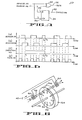
- shaft 12 upon rotation of knob 10, shaft 12 will rotate. Coupled to shaft 12 is a disc 20 having optical gradations 22 which permit the passage of light from source 25 therethough. A second set of gradations are present on plate 27. Rotation of disc 20 results in an optical interference pattern in the light energy falling on sensors 24 and 26 due to the relative motion between the slots on disc 20 and those present on plate 27. In particular the gradations present on plate 27 result in the production of the respective waveforms by sensors 24 and 26 having a quadrature relationship, as illustrated in FIGURE 3. The manner in which the gradations are placed on plate 27 to result in the waveforms illustrated in FIGURE 3 is well known to those skilled in the art.
- FIGURE 4 A circuit for the decoding of the waveforms produced by sensor 24 and 26 in response to rotation of knob 10 is shown in FIGURE 4.
- Input signals from sensors 24 and 26 are supplied as inputs to EXCLUSIVE-OR gate 30 whose output RATE 32 is a sequence of pulses proportional to angular displacement of shaft 12, and the rate of which proportional to angular velocity of shaft 12.
- Flip-flop 34 is a D-type flip-flop. The output from sensor 24 is supplied to the clock input 36 and the output from sensor 26 is supplied to the D input 38 of flip-flop 34. Consequently upon every high-to-low transition occurring on the output signal from sensor 24, the output direction 40 of flip-flop 34 will assume the corresponding state of the output from sensor 26.
- FIGURE 4 The operation of the circuit illustrated in FIGURE 4 can be further understood by reference to the waveforms illustrated in FIGURE 5.
- FIGURE 5(a) and 5(b) illustrate the output waveforms from sensor 24 and 26 respectively in response to rotation of disc 20 (FIGURE 2).
- FIGURE 5(c) illustrates the corresponding output 40 from flip-flop 34.
- FIGURE 5(d) illustrates the corresponding output 32 from EXCLUSIVE-OR gate 30.
- FIGURE 2 As knob 10 (FIGURE 2) is rotated in a first direction, the outputs produced by sensors 24 and 26 will be as illustrated in FIGURE 5(a) and 5(b). At time t l , the high-to-low transition occurring on the ouput of sensor 24 will result in the state of flip-flop 34 assuming the current state of the signal from sensor 26 (FIGURE 5(b)). Consequently, the output direction 40 from flip-flop 34 will assume a high state, as illustrated in FIGURE 5(c).
- FIGURE 5(d) illustrates the corresponding output 32 from EXCLUSIVE-OR gate 30.
- a Two Channel Incremental Optical Encoder manufactured by Hewlett Packard, series HEDS-5000 is used to implement the above described tachometer, as more fully described in Hewlett Packard 28mm DIAMETER TWO CHANNEL INCREMENTAL OPTICAL ENCODER KIT tentative data sheet dated January 1981, number 5953-0469 (1/81), which is incorporated by reference herein.
- output transducer means 15 (FIGURE 1) is implemented using a particle brake, best illustrated in FIGURE 6.
- Affixed to shaft 12 is a disc 50 having a plurality of slots 52.
- Disc 50 is constructed of non-magnetic material, and is completely enclosed in a non-magnetic housing 54 which is filled with magnetic particles 56 in a powder form.
- Magnetic flux 58 produced by coil 60 in response to current I 62 is positioned normal to the surface of disc 50 and in alignment with a portion of the locus of positions occupied by slots 52.
- a magnetic flux 58 is created, the amount of which being directly proportional to the amount of current I 62 applied to coil 60.
- a particle brake as above described is commercially available from DANA INDUSTRIAL under the trademark SOFSTEP, as more fully described in DANA INDUSTRIAL Simplatrol catalog S-1100 which is incorporated by reference herein.
- the amount of drag associated with rotational motion of potentiometers in the past is constant, a number of new and distinct programmable tactile responses are easily available in accordance with the present invention.
- the amount of drag produced can vary in any desired relation to angular position, angular velocity, direction of rotation, or any parameter or condition of interest.
- the present invention in a complex process control application wherein the present invention is used to control a critical parameter, the-existence of an undesirable condition resulting either from parameter adjustment (or other unrelated causes) can be easily communicated to the human operator by an increase in the amount of drag; e.g., if the rate of increase of a parameter associated with angular position is producing undesirable results, this condition could be communicated to the human operator by increasing the amount of drag in an amount appropriate to the particular conditions present.
- limits can easily by placed on the amount of permissible angular rotation, i.e., end stops could be positioned at any desired angular location.
- the relative angular location of points of interest can be easily communicated to the human operator, i.e., detents can be placed at any desired angular positions.
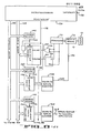
- FIGURE 7 illustrates an embodiment of a soft knob with tactile feedback in an application having programmable clockwise and counter clockwise end of rotation stops, a programmable detent, and a different amount of drag associated with each direction of rotation, providing an analog control output to control an application of interest, as well as having the ability to provide a tactile indication of information either from the application of interest or from an unrelated application.
- Rate 32 and direction 40 are supplied to the respective count and direction inputs of up/down counter 80.
- up/down counter 80 will, in response to rate 32, count in either a numerically increasing or decreasing sequence. Consequently the numeric value of the count present in up/down counter 80 will correspond to the angular position of knob 10.
- the output from up/down counter 80 is supplied to upper limit comparison means 82, mid-range detent means 84, lower limit comparison means 86 and digital to analog converter 87.
- the output 89 from digital to analog converter 87 is an analog signal proportional to the angular position of knob 10, and would be used to control the particular application 91 of interest where a control voltage in an analog format may be desired.
- a corrresponding digital control signal is available directly from the output from up/down counter 80 for applications requiring such.
- Upper limit comparison means 82, mid-range detent means 84 and lower limit comparison means 82 each function to compare the numeric value of the digital output signal from up/down counter 80 with pre-selected numeric values which can be defined depending upon the particular application, e.g., such as by thumbwheel switch settings.
- the output from up/down counter 80 is simultaneously applied to upper limit comparison means 82, mid-range detent means 84 and lower limit comparison means 86.
- the particle brake time constant determined by the equivilent inductance-and resistance presented by the associated electrical circuit, hereinafter referred to as the particle brake time constant. Consequently, for a perceivable tactile indication to occur in response to a current pulse, the duration of the current pulse must exceed a minimum time period determined by - the above discussed particle brake time constant.
- knob 10 is such to result in the production of a true indication from mid-range detent means 84 of a pulse having a duration less than the particle brake time constant, e.g., employing a tachometer having a large number of slot 22 (FIGURE 2), and the rotation of knob 10 at a large angular velocity.
- the output from mid-range detent means 84 is simultaneously applied as one input to OR gate 92 and as a trigger input to one shot 94.
- the period of the pulse produced by one shot -94 is adjusted such that it is greater than the above discussed particle brake time constant.
- the output from one shot 94 is applied as the second input to OR gate 92. Consequently the output 96 from OR gate 92 is a signal having a minimum duration greater than the particle brake time constant, indicative of agreement between the angular position of knob 10 and a pre- defined angular position at which a detent tactile response is desired.
- the numeric values 100 and 102 presented in a digital format to multiplexer 98 represent the respective desired amounts of drag to be presented to rotation of knob 10 in each direction.
- Multiplexer 98 in response to the binary state of the signal supplied to SELECT input 104 will supply either the clockwise drag value 100 or the counter clockwise drag value 102 as the respective output 106 from multiplexer 98.
- direction 40 from flip-flop 34 is supplied as the input to select 104 of multiplexer 98, the direction of rotation of knob 10 will consequently determine which of the two inputs to multiplexer 98 will be supplied as the output 106 therefrom.
- the output 106 from multiplexer 98 is supplied as an input to digital to analog converter 108, whose output 110 is an analog signal proportional to the binary value of the digital signal supplied as an input thereto from mulitplexer 98. Consequently, the resulting ouput signal 110 from digital to analog converter 108 is an analog signal representative of the amount of desired drag to be presented to rotation of knob 10.
- Operational amplifier 112 and resistors 114, 116, 117, 118,119 and 120 associated therewith form an analog voltage summing means whose output 122 is an analog voltage proportional to the algebratic sum of the respective input voltages, i.e., the voltages present in the output 90 from OR gate 88, an analog input voltage 121 from the application of interest, the output 96 from OR gate 92, an analog input voltage from an external source unrelated to the application 123, and the ouput 110 from digital to analog converter 108.
- Resistors 116, 117, 118 119 and 120 are each individually adjustable as each determines the amount of amplification which will result in the analog output 122 from operational amplifier 112 in response to the level of the associated analog voltage applied thereto.
- the resulting analog voltage output 122 is used to control the current and hence the amount of rotational friction or drag produced by particle brake 72.
- each of the inputs to the analog summing circuit can be adjusted by adjusting the values of resistors'116, 117, 118, 119 and 120, the resulting amount of rotational friction produced by upper or lower comparison means 82 or 86, mid-range detent means 84, the inputs 121 or 123 from either the application of interest or from the external source unrelated to the application, respectively and the directionally dependent drag represented by the output 110 from digital to analog converter 108 respectively, can be independently adjusted to produce the desired tactile response.
- resistor 116 will determine the amount of current supplied to particle brake 72 when the angular position of knob 10 equals one of the pre-defined limits of rotation, resistor 116 would be adjusted to simulate the desired tactile response indicative of an end stop.
- resistor 117 will control the amount of rotational resistance produced in response to input 121 from the application of interest.
- resistor 118 will determine the amount of rotational friction produced in response to the angular position of knob 10 equalling the pre- defined detent position.
- resistor 119 will control the amount of rotational resistance produced in response to input 123 from an external source unrelated to the application of interest.
- resistor 120 will determine the amount of continuous drag produced in response to clockwise or counter clockwise rotation as defined by clockwise drag value 100 and counter clockwise drag value 102.
- FIGURE 7 illustrates one preferred embodiment of a soft knob having tactile feedback with pre-selectable end stops, detent, as well as a continuous drag effect which is dependent upon the direction of rotation, which can further produce tactile indication responsive to signals from both the application of interest as well as an external source unrelated to the application.
- FIGURE 8 illustrates one possible embodiment of such a design.
- FIGURE 9 illustrates an example of a corresponding program in a flow diagram form which could be used in connection therewith.
- microprocessor 130 has associated therewith address buss 132, data buss 134, as well as interrupt input 136, and READ/WRITE output 138.
- Interrupt input 136 to microprocessor 130 serves to notify the microprocessor of the occurrence of external events so that appropriate actions can be taken.
- a 30 Hz signal is effectively supplied to interrupt input 136 to result in the regular, periodic execution by microprocessor 130 of a desired action, as more fully described hereinafter.
- READ/WRITE' signal 138 serves to indicate the nature of the operation occurring with respect to data buss 134 and address buss 132, i.e., whether the current operation is the input of information to, or the output of information from microprocessor 130.
- Address decode 140, 141, 142, 143, and 144 each are designed to recognize a unique pre-defined address associated with drag register 146, application input register 145, counter register 148, external source input register 147 and application output register 150, respectively.
- address buss 132 In response to the presence of an address value on address buss 132 equal to the pre-defined address of drag register 146, application input register 145, counter register 148, external source input register 147 or application output register 150, the corresponding respective enable signal 152, 153, 154, 155 or 156 will be produced.
- Enable signal 152, 154 or 156 function to effect the transfer of the current numeric value present on data buss 134 to drag register 146, counter register 148 or application register 150 respectively.
- analog to digital converter 159 and 161 function to convert the input analog voltage from application 121 and the input analog voltage from external source unrelated to application 123 to corresponding digital values for subsequent transfer to data buss 134.
- Count register 148 is a 8-bit presetable up/ down counter. The direction of counting is determined by the state of direction signal 40 and in response thereto, counter register 148 will either increment or decrement the current value of the count therein upon the occurrence of each rate pulse 32.
- the value present in count register 148 can be pre-set in response to the presence of the appropriate address on address buss 132 to produce enable signal 154 to result in the transfer of the current value of the digital signal present on data buss 134 to count register 148. Thereafter that value will be either incremented or decremented in response to direction signal 40 and rate signal 32.
- microprocessor 130 can read the value present in count register 148 by the specifying of the pre-defined address associated with address decode 142, which will result in the contents of counter register 148 being transferred to data buss 134.
- microprocessor 130 can dynamically change the drag or rotational resistance presented to the rotation of knob 10 by controlling the current supplied to particle brake 72 through the use of drag register 146 and digital to analog converter 162.
- microprocessor 130 can provide a control signal in a digital format from the output of application output register 150 for control of applications requiring a control signal in a digital format, or can provide a control signal in an analog format from the output of digital to analog converter 160 for control of applications requiring a control signal in an analog format.
- Microprocessor 130 can either store a digital value in counter register 148 or read the current value of the contents of counter register 148.
- microprocessor 130 could receive input information from either the application of interest, or from an unrelated source, as illustrated by analog input signals 121 and 123. It is of course clear that while signals 121 and 123 have been shown to be in an analog format, the format of said signals could likewise be in a digital format. Input signal 121 and 123 illustrates that information from either the application of interest or some other unrelated source could be made available to microprocessor 130 for appropriate response.
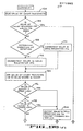
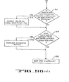
- FIGURE 9 illustrates in a flow chart format a program which would provide not only programmable end stops to the angular rotation of knob 10 detents, drag on the rotation of knob 10 which is both direction and angular position dependent, as well as responsiveness to input information from both the application of interest and a second unrelated application.
- FIGURE 9(a) illustrates an initilization routine
- FIGURE 9(b) the main body of the control program.
- the microprocessor initially stores a zero value in a location called COUNT, indicated by step 170.
- Location COUNT will be used for temporary storage of a value which will be frequently compared with the contents of count register 148 to determine the occurrence of various events in connection with the rotation of knob 10, as will be more fully described hereinafter.
- steps 172 and 174 set the contents of count register 148 and drag register 146 to zero.
- the microprocessor executes the general control routine illustrated in FIGURE 9(b) in response to the receipt of an interrupt, which in the preferred embodiment occur at regular spaced intervals of time each thirtieth of a second.
- microprocessor 130 in response to ; the receipt of an interrupt, microprocessor 130 first reads the value present in count register 148 in step 180, and determines if the number so read is equal to zero in 182 or a positive or a negative number in step 188. If knob 10 has been rotated in one direction, the value in count register 148 will be a positive number. Conversely, if knob 10 has been rotated in the opposite direction, the value present in count register 148 will be a negative number. Consequently the algebratic sign of the number found in count.register 148 will indicate the direction which knob 10 has been rotated.
- step 182 If the value found in count register 148 in step 182 is zero, this would indicate that the angular position bf knob 10 has not changed since the last time it was checked by microprocessor 130, as the last task done in the general processing routine in step 184 is the setting of the value in count register 148 to zero. Consequently, if the value found in count register 148 in step 180 is zero, microprocessor goes to step 210 as further discussed hereinafter.
- Step 188 determines the direction which knob 10 has been rotated, from the algebratic sign of the number present in count register 148 as previously discussed. If the detected direction of rotation was in a first direction, indicated in FIGURE 9(b) as a value greater than zero, the-value stored in drag register 146 is incremented in step 190 to effect an increase in the drag presented to rotation of knob 10. If the detected direction of rotation is in the opposite direction by the presence of a value less than zero, the value stored in drag register 146 is decremented in step 192 to effect a decrease in the drag presented to rotation of knob 10.
- the numeric value found in count register 148 is added to the number stored in COUNT in step 194.
- the results of the addition is a number indicative of the angular position of knob 10.
- the current position of knob 10 as determined above is checked in steps 196 and 198 to see if it is equal to or exceeds the maximum amount of angular rotation in either direction, by comparing the value of COUNT with the corresponding numeric values associated with the desired extremes of rotations. If the condition is found to be true, a maximum torque is produced in a particle brake 72 by the storing of appropriate numeric value in drag register 146 to inhibit further rotation of knob 10 in step 200. Thereafter, microprocessor will output to application register 150 the current value stored in COUNT which is indicative of the angular position of knob 10 in step 202. Thereafter, as knob 10 is at an extreme of permissible rotation, nothing further is to be done, and the microprocessor will reset the value in count register 148 to zero in step 184 and perform the steps starting with block 210, as more fully described hereinafter.
- the microprocessor next checks the value of COUNT against the respective values which are indicative of the position of a detent in steps 204 and 206. If agreement is found, the microprocessor in step 208 outputs the appropriate numberic value to drag register 146 to effect the desired rotational resistance in particle brake 72 to indicate the desired detent. If the result of the comparison of the value of COUNT against the values associated with the location of detents in steps 198 and 200 does not agree, this would indicate that the position of knob 10 is not currently located at an angular position which would correspond to a desired detent position.
- the value in count register 148 is set to zero in step 184 so that any subsequent change in position will be detected in steps 180 and 182 when the general control routine is again executed upon receipt of an interrupt.
- microprocessor 130 checks the status of the input analog voltage 123 from external source unrelated to the application in step 210.
- This step and the associated address decode 143, external source input register 147 and analog to digital converter 161 illustrate the example, events from unrelated applications (line 18 in Figure 1).
- microprocessor 130 checks the status of input analog voltage 121 from application in step 214.
- This step and the associated address decode 141, application input register 145 and analog to gital converter 159 (FIGURE 8) illustrate the example, events from the application.
- This appropriate action in response to an affirmative indication from decision block 214 (FIGURE 9(b)) would result in the appropriate action as, for example, the output of a value to drag register 146 to effect a rotational resistance in particle brake 72, as indicated in block 216.
- microprocessor 130 has completed the processing of any information from knob 10, made the necessary adjustments in the rotational resistance presented by particle brake 72, and made the corresponding adjustment in the analog voltage 164 which would be controlling the particular application of interest, and checked the status of input information from both the application of interest as well as an unrelated application. Thereafter, microprocessor will wait for the next regularly occurring interrupt in step 186, at which point microprocessor 130 will again execute the above described control program.
- microprocessor 130 could go on to process other tasks, if desired.
Landscapes
- Physics & Mathematics (AREA)
- General Physics & Mathematics (AREA)
- Engineering & Computer Science (AREA)
- Automation & Control Theory (AREA)
- Feedback Control In General (AREA)
- Input From Keyboards Or The Like (AREA)
- Programmable Controllers (AREA)
- Control Of Position Or Direction (AREA)
- Control Of Electric Motors In General (AREA)
- Mechanical Control Devices (AREA)
Priority Applications (2)
| Application Number | Priority Date | Filing Date | Title |
|---|---|---|---|
| DE8989200571T DE3382593T2 (de) | 1982-09-17 | 1983-09-09 | Dynamisch interaktive steuerungsanlage. |
| AT83305283T ATE55192T1 (de) | 1982-09-17 | 1983-09-09 | Dynamisch interaktiv reagierendes steuerungsgeraet und anlage. |
Applications Claiming Priority (2)
| Application Number | Priority Date | Filing Date | Title |
|---|---|---|---|
| US419632 | 1982-09-17 | ||
| US06/419,632 US4560983A (en) | 1982-09-17 | 1982-09-17 | Dynamically interactive responsive control device and system |
Related Child Applications (2)
| Application Number | Title | Priority Date | Filing Date |
|---|---|---|---|
| EP89103905.9 Division-Into | 1989-03-06 | ||
| EP89200571.1 Division-Into | 1989-03-07 |
Publications (3)
| Publication Number | Publication Date |
|---|---|
| EP0111992A2 true EP0111992A2 (de) | 1984-06-27 |
| EP0111992A3 EP0111992A3 (en) | 1986-08-20 |
| EP0111992B1 EP0111992B1 (de) | 1990-08-01 |
Family
ID=23663065
Family Applications (1)
| Application Number | Title | Priority Date | Filing Date |
|---|---|---|---|
| EP83305283A Expired - Lifetime EP0111992B1 (de) | 1982-09-17 | 1983-09-09 | Dynamisch interaktiv reagierendes Steuerungsgerät und Anlage |
Country Status (5)
| Country | Link |
|---|---|
| US (1) | US4560983A (de) |
| EP (1) | EP0111992B1 (de) |
| JP (2) | JPH0697401B2 (de) |
| CA (1) | CA1235774A (de) |
| DE (1) | DE3381775D1 (de) |
Cited By (8)
| Publication number | Priority date | Publication date | Assignee | Title |
|---|---|---|---|---|
| EP0131357A3 (en) * | 1983-05-16 | 1986-10-22 | Koyo Denshi Kogyo Kabushiki Kaisha (Koyo Electronics Industries Co. Ltd.) | Control apparatus |
| EP0177441B1 (de) * | 1984-08-31 | 1989-12-20 | Fritz Gegauf Ag Bernina-Nähmaschinenfabrik | Einstell- und Anzeigevorrichtung an einer elektronischen Nähmaschine |
| EP0609363A4 (de) * | 1991-10-24 | 1994-11-09 | Lex Computer & Management | Antrieb mit elektronisch steuerbarer reaktionsempfindlichkeit. |
| EP0677933A3 (de) * | 1994-04-12 | 1995-12-13 | Studer Professional Audio Ag | Stellglied mit taktiler Rückkopplung. |
| US5889670A (en) * | 1991-10-24 | 1999-03-30 | Immersion Corporation | Method and apparatus for tactilely responsive user interface |
| US8364342B2 (en) | 2001-07-31 | 2013-01-29 | Immersion Corporation | Control wheel with haptic feedback |
| EP2604742A1 (de) * | 2011-12-13 | 2013-06-19 | Miele & Cie. KG | Bedienelement für ein Haushaltsgerät, Bedieneinheit für ein solches Haushaltsgerät mit einem solchen Bedienelement und Haushaltsgerät mit einer solchen Bedieneinheit und/ oder einem solchen Bedienelement |
| US10179540B2 (en) | 2004-08-20 | 2019-01-15 | Immersion Corporation | Systems and methods for providing haptic effects |
Families Citing this family (85)
| Publication number | Priority date | Publication date | Assignee | Title |
|---|---|---|---|---|
| JP2714164B2 (ja) * | 1989-07-31 | 1998-02-16 | 株式会社東芝 | 三次元画像表示装置 |
| JPH073808B2 (ja) * | 1990-04-19 | 1995-01-18 | アキュ グスタフソ | プリント回路上へのコイル組立て方法 |
| DE4026915A1 (de) * | 1990-08-25 | 1992-02-27 | Vdo Schindling | Anzeigevorrichtung mit schrittmotor |
| US5309140A (en) * | 1991-11-26 | 1994-05-03 | The United States Of America As Represented By The Secretary Of The Navy | Feedback system for remotely operated vehicles |
| US5189355A (en) * | 1992-04-10 | 1993-02-23 | Ampex Corporation | Interactive rotary controller system with tactile feedback |
| US5296871A (en) * | 1992-07-27 | 1994-03-22 | Paley W Bradford | Three-dimensional mouse with tactile feedback |
| US5790108A (en) | 1992-10-23 | 1998-08-04 | University Of British Columbia | Controller |
| US6801008B1 (en) | 1992-12-02 | 2004-10-05 | Immersion Corporation | Force feedback system and actuator power management |
| US5629594A (en) * | 1992-12-02 | 1997-05-13 | Cybernet Systems Corporation | Force feedback system |
| US6433771B1 (en) | 1992-12-02 | 2002-08-13 | Cybernet Haptic Systems Corporation | Haptic device attribute control |
| US7345672B2 (en) | 1992-12-02 | 2008-03-18 | Immersion Corporation | Force feedback system and actuator power management |
| US5451924A (en) * | 1993-01-14 | 1995-09-19 | Massachusetts Institute Of Technology | Apparatus for providing sensory substitution of force feedback |
| US5734373A (en) | 1993-07-16 | 1998-03-31 | Immersion Human Interface Corporation | Method and apparatus for controlling force feedback interface systems utilizing a host computer |
| US5731804A (en) * | 1995-01-18 | 1998-03-24 | Immersion Human Interface Corp. | Method and apparatus for providing high bandwidth, low noise mechanical I/O for computer systems |
| US5739811A (en) | 1993-07-16 | 1998-04-14 | Immersion Human Interface Corporation | Method and apparatus for controlling human-computer interface systems providing force feedback |
| US5721566A (en) | 1995-01-18 | 1998-02-24 | Immersion Human Interface Corp. | Method and apparatus for providing damping force feedback |
| US5805140A (en) | 1993-07-16 | 1998-09-08 | Immersion Corporation | High bandwidth force feedback interface using voice coils and flexures |
| US5821920A (en) | 1994-07-14 | 1998-10-13 | Immersion Human Interface Corporation | Control input device for interfacing an elongated flexible object with a computer system |
| US20030040361A1 (en) | 1994-09-21 | 2003-02-27 | Craig Thorner | Method and apparatus for generating tactile feedback via relatively low-burden and/or zero burden telemetry |
| US5666138A (en) | 1994-11-22 | 1997-09-09 | Culver; Craig F. | Interface control |
| US6850222B1 (en) | 1995-01-18 | 2005-02-01 | Immersion Corporation | Passive force feedback for computer interface devices |
| US5691898A (en) | 1995-09-27 | 1997-11-25 | Immersion Human Interface Corp. | Safe and low cost computer peripherals with force feedback for consumer applications |
| US6166723A (en) | 1995-11-17 | 2000-12-26 | Immersion Corporation | Mouse interface device providing force feedback |
| US7113166B1 (en) | 1995-06-09 | 2006-09-26 | Immersion Corporation | Force feedback devices using fluid braking |
| DE19528457C2 (de) * | 1995-08-03 | 2001-03-08 | Mannesmann Vdo Ag | Bedieneinrichtung |
| US5959613A (en) | 1995-12-01 | 1999-09-28 | Immersion Corporation | Method and apparatus for shaping force signals for a force feedback device |
| US5999168A (en) | 1995-09-27 | 1999-12-07 | Immersion Corporation | Haptic accelerator for force feedback computer peripherals |
| US6639581B1 (en) | 1995-11-17 | 2003-10-28 | Immersion Corporation | Flexure mechanism for interface device |
| US6704001B1 (en) | 1995-11-17 | 2004-03-09 | Immersion Corporation | Force feedback device including actuator with moving magnet |
| US5825308A (en) | 1996-11-26 | 1998-10-20 | Immersion Human Interface Corporation | Force feedback interface having isotonic and isometric functionality |
| WO1997020305A1 (en) | 1995-11-30 | 1997-06-05 | Virtual Technologies, Inc. | Tactile feedback man-machine interface device |
| US8508469B1 (en) | 1995-12-01 | 2013-08-13 | Immersion Corporation | Networked applications including haptic feedback |
| US6028593A (en) | 1995-12-01 | 2000-02-22 | Immersion Corporation | Method and apparatus for providing simulated physical interactions within computer generated environments |
| US6300936B1 (en) | 1997-11-14 | 2001-10-09 | Immersion Corporation | Force feedback system including multi-tasking graphical host environment and interface device |
| SE519661C2 (sv) | 1996-02-23 | 2003-03-25 | Immersion Corp | Pekdon och förfarande för markering av grafiska detaljer på en display med sensorisk återkoppling vid påträffande av nämnda detalj |
| FR2753853B1 (fr) * | 1996-09-26 | 1999-01-15 | Dispositif distributeur de titres de transport ou analogue equipe d'un organe de commande rotatif a effet tactile | |
| US6411276B1 (en) | 1996-11-13 | 2002-06-25 | Immersion Corporation | Hybrid control of haptic feedback for host computer and interface device |
| US7489309B2 (en) | 1996-11-26 | 2009-02-10 | Immersion Corporation | Control knob with multiple degrees of freedom and force feedback |
| US6686911B1 (en) | 1996-11-26 | 2004-02-03 | Immersion Corporation | Control knob with control modes and force feedback |
| US6154201A (en) * | 1996-11-26 | 2000-11-28 | Immersion Corporation | Control knob with multiple degrees of freedom and force feedback |
| US6956558B1 (en) | 1998-03-26 | 2005-10-18 | Immersion Corporation | Rotary force feedback wheels for remote control devices |
| US6636197B1 (en) | 1996-11-26 | 2003-10-21 | Immersion Corporation | Haptic feedback effects for control, knobs and other interface devices |
| US6128006A (en) * | 1998-03-26 | 2000-10-03 | Immersion Corporation | Force feedback mouse wheel and other control wheels |
| US6320487B1 (en) * | 1997-03-25 | 2001-11-20 | Lear Automotive Dearborn, Inc. | Control device with tailored feedback |
| US6020875A (en) | 1997-10-31 | 2000-02-01 | Immersion Corporation | High fidelity mechanical transmission system and interface device |
| US6104382A (en) | 1997-10-31 | 2000-08-15 | Immersion Corporation | Force feedback transmission mechanisms |
| US6281651B1 (en) | 1997-11-03 | 2001-08-28 | Immersion Corporation | Haptic pointing devices |
| US6252583B1 (en) | 1997-11-14 | 2001-06-26 | Immersion Corporation | Memory and force output management for a force feedback system |
| US6256011B1 (en) | 1997-12-03 | 2001-07-03 | Immersion Corporation | Multi-function control device with force feedback |
| US6878066B2 (en) * | 1998-02-13 | 2005-04-12 | Freedom Wave Llc | Wireless game control units |
| US6067077A (en) * | 1998-04-10 | 2000-05-23 | Immersion Corporation | Position sensing for force feedback devices |
| US6300938B1 (en) | 1998-04-13 | 2001-10-09 | Immersion Corporation | Multiple-cylinder control device for computers and other electronic apparatus |
| US6429846B2 (en) | 1998-06-23 | 2002-08-06 | Immersion Corporation | Haptic feedback for touchpads and other touch controls |
| US6184868B1 (en) | 1998-09-17 | 2001-02-06 | Immersion Corp. | Haptic feedback control devices |
| US7038667B1 (en) | 1998-10-26 | 2006-05-02 | Immersion Corporation | Mechanisms for control knobs and other interface devices |
| US6664666B2 (en) * | 1998-12-23 | 2003-12-16 | Engineering Matters, Inc. | Motor assembly allowing output in multiple degrees of freedom |
| US6903721B2 (en) * | 1999-05-11 | 2005-06-07 | Immersion Corporation | Method and apparatus for compensating for position slip in interface devices |
| AU6346400A (en) * | 1999-07-15 | 2001-02-05 | Richard B. Himmelstein | Communication device for efficiently accessing internet resources |
| US9607041B2 (en) | 1999-07-15 | 2017-03-28 | Gula Consulting Limited Liability Company | System and method for efficiently accessing internet resources |
| US7272637B1 (en) * | 1999-07-15 | 2007-09-18 | Himmelstein Richard B | Communication system and method for efficiently accessing internet resources |
| US6564168B1 (en) | 1999-09-14 | 2003-05-13 | Immersion Corporation | High-resolution optical encoder with phased-array photodetectors |
| US6693626B1 (en) | 1999-12-07 | 2004-02-17 | Immersion Corporation | Haptic feedback using a keyboard device |
| US6822635B2 (en) | 2000-01-19 | 2004-11-23 | Immersion Corporation | Haptic interface for laptop computers and other portable devices |
| US7084854B1 (en) | 2000-09-28 | 2006-08-01 | Immersion Corporation | Actuator for providing tactile sensations and device for directional tactile sensations |
| US6937033B2 (en) | 2001-06-27 | 2005-08-30 | Immersion Corporation | Position sensor with resistive element |
| US20040040800A1 (en) | 2002-07-31 | 2004-03-04 | George Anastas | System and method for providing passive haptic feedback |
| GB2414319A (en) | 2002-12-08 | 2005-11-23 | Immersion Corp | Methods and systems for providing haptic messaging to handheld communication devices |
| US8830161B2 (en) | 2002-12-08 | 2014-09-09 | Immersion Corporation | Methods and systems for providing a virtual touch haptic effect to handheld communication devices |
| US8059088B2 (en) | 2002-12-08 | 2011-11-15 | Immersion Corporation | Methods and systems for providing haptic messaging to handheld communication devices |
| WO2004109488A2 (en) | 2003-05-30 | 2004-12-16 | Immersion Corporation | System and method for low power haptic feedback |
| DE102004016121B4 (de) * | 2004-04-01 | 2008-11-27 | Siemens Ag | Bedienvorrichtung zum Verfahren mindestens einer Maschinenachse einer Werkzeug- oder Produktionsmaschine |
| US7522152B2 (en) | 2004-05-27 | 2009-04-21 | Immersion Corporation | Products and processes for providing haptic feedback in resistive interface devices |
| US7198137B2 (en) | 2004-07-29 | 2007-04-03 | Immersion Corporation | Systems and methods for providing haptic feedback with position sensing |
| US8441433B2 (en) | 2004-08-11 | 2013-05-14 | Immersion Corporation | Systems and methods for providing friction in a haptic feedback device |
| US8013847B2 (en) | 2004-08-24 | 2011-09-06 | Immersion Corporation | Magnetic actuator for providing haptic feedback |
| US8803796B2 (en) | 2004-08-26 | 2014-08-12 | Immersion Corporation | Products and processes for providing haptic feedback in a user interface |
| US8002089B2 (en) | 2004-09-10 | 2011-08-23 | Immersion Corporation | Systems and methods for providing a haptic device |
| US9046922B2 (en) | 2004-09-20 | 2015-06-02 | Immersion Corporation | Products and processes for providing multimodal feedback in a user interface device |
| US7764268B2 (en) | 2004-09-24 | 2010-07-27 | Immersion Corporation | Systems and methods for providing a haptic device |
| US7825903B2 (en) | 2005-05-12 | 2010-11-02 | Immersion Corporation | Method and apparatus for providing haptic effects to a touch panel |
| JP2007311174A (ja) * | 2006-05-18 | 2007-11-29 | Tokai Rika Co Ltd | 節度装置 |
| US9582178B2 (en) | 2011-11-07 | 2017-02-28 | Immersion Corporation | Systems and methods for multi-pressure interaction on touch-sensitive surfaces |
| US20180164996A1 (en) * | 2016-12-12 | 2018-06-14 | Logitech Europe S.A. | Contextually-based functional assignment for a user-manipulable element on an input device |
| JP6519959B2 (ja) * | 2017-03-22 | 2019-05-29 | カシオ計算機株式会社 | 操作処理装置、再生装置、操作処理方法およびプログラム |
| JP7324060B2 (ja) * | 2019-06-11 | 2023-08-09 | ファナック株式会社 | 位置検出装置 |
Family Cites Families (14)
| Publication number | Priority date | Publication date | Assignee | Title |
|---|---|---|---|---|
| US3497668A (en) * | 1966-08-25 | 1970-02-24 | Joseph Hirsch | Tactile control system |
| US3701092A (en) * | 1970-11-09 | 1972-10-24 | Albert Howard Hasbrook | Vehicular attitude-control display |
| US3919691A (en) * | 1971-05-26 | 1975-11-11 | Bell Telephone Labor Inc | Tactile man-machine communication system |
| US4011510A (en) * | 1975-01-23 | 1977-03-08 | The Foxboro Company | Signal-responsive apparatus having magnetic-particle-friction memory |
| JPS5853418B2 (ja) * | 1976-09-15 | 1983-11-29 | ソニー株式会社 | モ−タ制御装置 |
| DE2707208B2 (de) * | 1977-02-19 | 1979-04-12 | Diehl Gmbh & Co, 8500 Nuernberg | Eingabevorrichtung |
| DE2715870B2 (de) * | 1977-04-09 | 1981-07-16 | Carl Schenck Ag, 6100 Darmstadt | Verfahren zur schnellen Veränderung des Bremsmomentes einer Wirbelstrombremse und Vorrichtung zur Durchführung des Verfahrens |
| DE2731970C3 (de) * | 1977-07-15 | 1987-04-16 | Diehl GmbH & Co, 8500 Nürnberg | Ansteueranordnung für das Anzeigefeld einer elektronischen Herdschaltuhr |
| US4195802A (en) * | 1978-04-28 | 1980-04-01 | The Ohio State University | Kinesthetic tactile display system |
| GB2120815B (en) * | 1979-02-05 | 1984-08-15 | Turnright Controls | Improvements in or relating to programmable timing apparatus |
| US4244120A (en) * | 1979-06-11 | 1981-01-13 | The United States Of America As Represented By The Secretary Of The Navy | Acceleration cueing simulation device |
| JPS568003U (de) * | 1979-06-29 | 1981-01-23 | ||
| DE3031957A1 (de) * | 1980-08-25 | 1982-03-18 | Licentia Patent-Verwaltungs-Gmbh, 6000 Frankfurt | Digitale einrichtung zur mehrfachen, nacheinander erfolgenden einstellung von funktionen und diesen zugeordneten werten |
| DE3031966C2 (de) * | 1980-08-25 | 1983-03-03 | Licentia Patent-Verwaltungs-Gmbh, 6000 Frankfurt | Einrichtung zur handbetätigten Einstellung von bestimmten Funktionen mittels eines ersten Impulsgenerators und zur ebenfalls handbetätigten Einstellung diesen zuordenbaren Daten mittels eines zweiten Impulsgenerators |
-
1982
- 1982-09-17 US US06/419,632 patent/US4560983A/en not_active Expired - Lifetime
-
1983
- 1983-08-25 CA CA000435319A patent/CA1235774A/en not_active Expired
- 1983-09-09 DE DE8383305283T patent/DE3381775D1/de not_active Expired - Lifetime
- 1983-09-09 EP EP83305283A patent/EP0111992B1/de not_active Expired - Lifetime
- 1983-09-13 JP JP58167635A patent/JPH0697401B2/ja not_active Expired - Lifetime
-
1994
- 1994-07-05 JP JP6174932A patent/JPH0820881B2/ja not_active Expired - Lifetime
Cited By (12)
| Publication number | Priority date | Publication date | Assignee | Title |
|---|---|---|---|---|
| EP0131357A3 (en) * | 1983-05-16 | 1986-10-22 | Koyo Denshi Kogyo Kabushiki Kaisha (Koyo Electronics Industries Co. Ltd.) | Control apparatus |
| EP0177441B1 (de) * | 1984-08-31 | 1989-12-20 | Fritz Gegauf Ag Bernina-Nähmaschinenfabrik | Einstell- und Anzeigevorrichtung an einer elektronischen Nähmaschine |
| EP0609363A4 (de) * | 1991-10-24 | 1994-11-09 | Lex Computer & Management | Antrieb mit elektronisch steuerbarer reaktionsempfindlichkeit. |
| US5414337A (en) * | 1991-10-24 | 1995-05-09 | Lex Computer And Management Corporation | Actuator having electronically controllable tactile responsiveness |
| US5559412A (en) * | 1991-10-24 | 1996-09-24 | Lex Computer And Management Corporation | Actuator having electronically controllable tactile responsiveness |
| US5889670A (en) * | 1991-10-24 | 1999-03-30 | Immersion Corporation | Method and apparatus for tactilely responsive user interface |
| EP1041473A3 (de) * | 1991-10-24 | 2004-12-29 | Immersion Corporation | Antrieb mit elektronisch steuerbarer Reaktionsempfindlichkeit |
| EP0677933A3 (de) * | 1994-04-12 | 1995-12-13 | Studer Professional Audio Ag | Stellglied mit taktiler Rückkopplung. |
| US8364342B2 (en) | 2001-07-31 | 2013-01-29 | Immersion Corporation | Control wheel with haptic feedback |
| US8554408B2 (en) | 2001-07-31 | 2013-10-08 | Immersion Corporation | Control wheel with haptic feedback |
| US10179540B2 (en) | 2004-08-20 | 2019-01-15 | Immersion Corporation | Systems and methods for providing haptic effects |
| EP2604742A1 (de) * | 2011-12-13 | 2013-06-19 | Miele & Cie. KG | Bedienelement für ein Haushaltsgerät, Bedieneinheit für ein solches Haushaltsgerät mit einem solchen Bedienelement und Haushaltsgerät mit einer solchen Bedieneinheit und/ oder einem solchen Bedienelement |
Also Published As
| Publication number | Publication date |
|---|---|
| JPS5966701A (ja) | 1984-04-16 |
| EP0111992A3 (en) | 1986-08-20 |
| JPH0820881B2 (ja) | 1996-03-04 |
| JPH0697401B2 (ja) | 1994-11-30 |
| EP0111992B1 (de) | 1990-08-01 |
| JPH07168601A (ja) | 1995-07-04 |
| US4560983A (en) | 1985-12-24 |
| CA1235774A (en) | 1988-04-26 |
| DE3381775D1 (de) | 1990-09-06 |
Similar Documents
| Publication | Publication Date | Title |
|---|---|---|
| US4560983A (en) | Dynamically interactive responsive control device and system | |
| EP2246770B1 (de) | Kraftrückgekoppelte Steuerungsknöpfe | |
| AU762226B2 (en) | Force feedback control wheels and knobs | |
| US5111005A (en) | Graphics tablet with n-dimensional capability | |
| US5189355A (en) | Interactive rotary controller system with tactile feedback | |
| US5633657A (en) | Mouse driver arrangement for providing advanced scrolling capabilities to a conventional mouse | |
| US5381080A (en) | Control device | |
| US8188989B2 (en) | Control knob with multiple degrees of freedom and force feedback | |
| US4859922A (en) | System for controlling the operating mode of a controlled apparatus | |
| US6642824B2 (en) | Magnetic encoder with snap action switch | |
| US7489309B2 (en) | Control knob with multiple degrees of freedom and force feedback | |
| US7233313B2 (en) | Control knob with multiple degrees of freedom and force feedback | |
| DE20014425U1 (de) | Mechanismen für Steuerknöpfe und andere Schnittstellenvorrichtungen | |
| EP0609363A1 (de) | Antrieb mit elektronisch steuerbarer reaktionsempfindlichkeit | |
| US5995079A (en) | Method for controlling a variable of a dialog box with cursor movement | |
| EP0323878B1 (de) | Dynamisch interaktive Steuerungsanlage | |
| EP0284057B1 (de) | Numerische Steuerung mit Tastkissen | |
| KR950012491B1 (ko) | 컴퓨터 시스템에서 가변 아날로그 값의 제어방법 및 시스템 | |
| US6353432B1 (en) | Mouse scroll input apparatus | |
| DE3382593T2 (de) | Dynamisch interaktive steuerungsanlage. | |
| JPH07261929A (ja) | コンピュータシミュレーション装置およびその入出力装置 | |
| JPH0713807B2 (ja) | マウス装置 | |
| JPS62267818A (ja) | 位置情報入力装置 | |
| Tourtellotte | A versatile dual axis programmable stepping motor controller for a personal computer: a specific application and tutorial for implementing a computer-controlled light microscope | |
| Real | Graphic data compressor for plotting instruments |
Legal Events
| Date | Code | Title | Description |
|---|---|---|---|
| PUAI | Public reference made under article 153(3) epc to a published international application that has entered the european phase |
Free format text: ORIGINAL CODE: 0009012 |
|
| AK | Designated contracting states |
Designated state(s): AT CH DE FR GB LI NL SE |
|
| PUAL | Search report despatched |
Free format text: ORIGINAL CODE: 0009013 |
|
| AK | Designated contracting states |
Kind code of ref document: A3 Designated state(s): AT CH DE FR GB LI NL SE |
|
| 17P | Request for examination filed |
Effective date: 19861108 |
|
| 17Q | First examination report despatched |
Effective date: 19880718 |
|
| GRAA | (expected) grant |
Free format text: ORIGINAL CODE: 0009210 |
|
| AK | Designated contracting states |
Kind code of ref document: B1 Designated state(s): AT CH DE FR GB LI NL SE |
|
| REF | Corresponds to: |
Ref document number: 55192 Country of ref document: AT Date of ref document: 19900815 Kind code of ref document: T |
|
| XX | Miscellaneous (additional remarks) |
Free format text: TEILANMELDUNG 89200571.1 EINGEREICHT AM 09/09/83. |
|
| REF | Corresponds to: |
Ref document number: 3381775 Country of ref document: DE Date of ref document: 19900906 |
|
| ET | Fr: translation filed | ||
| PLBE | No opposition filed within time limit |
Free format text: ORIGINAL CODE: 0009261 |
|
| STAA | Information on the status of an ep patent application or granted ep patent |
Free format text: STATUS: NO OPPOSITION FILED WITHIN TIME LIMIT |
|
| 26N | No opposition filed | ||
| PGFP | Annual fee paid to national office [announced via postgrant information from national office to epo] |
Ref country code: CH Payment date: 19930915 Year of fee payment: 11 |
|
| PGFP | Annual fee paid to national office [announced via postgrant information from national office to epo] |
Ref country code: SE Payment date: 19930917 Year of fee payment: 11 |
|
| PGFP | Annual fee paid to national office [announced via postgrant information from national office to epo] |
Ref country code: NL Payment date: 19930930 Year of fee payment: 11 |
|
| REG | Reference to a national code |
Ref country code: GB Ref legal event code: 732E |
|
| NLS | Nl: assignments of ep-patents |
Owner name: AMPEX SYSTEMS CORPORATION TE REDWOOD CITY, CALIFOR |
|
| PG25 | Lapsed in a contracting state [announced via postgrant information from national office to epo] |
Ref country code: SE Effective date: 19940910 |
|
| PG25 | Lapsed in a contracting state [announced via postgrant information from national office to epo] |
Ref country code: LI Effective date: 19940930 Ref country code: CH Effective date: 19940930 |
|
| EAL | Se: european patent in force in sweden |
Ref document number: 83305283.0 |
|
| PG25 | Lapsed in a contracting state [announced via postgrant information from national office to epo] |
Ref country code: NL Effective date: 19950401 |
|
| NLV4 | Nl: lapsed or anulled due to non-payment of the annual fee | ||
| REG | Reference to a national code |
Ref country code: CH Ref legal event code: PL |
|
| EUG | Se: european patent has lapsed |
Ref document number: 83305283.0 |
|
| REG | Reference to a national code |
Ref country code: GB Ref legal event code: 732E |
|
| REG | Reference to a national code |
Ref country code: GB Ref legal event code: IF02 |
|
| PGFP | Annual fee paid to national office [announced via postgrant information from national office to epo] |
Ref country code: GB Payment date: 20020904 Year of fee payment: 20 |
|
| PGFP | Annual fee paid to national office [announced via postgrant information from national office to epo] |
Ref country code: FR Payment date: 20020910 Year of fee payment: 20 |
|
| PGFP | Annual fee paid to national office [announced via postgrant information from national office to epo] |
Ref country code: AT Payment date: 20020911 Year of fee payment: 20 |
|
| PGFP | Annual fee paid to national office [announced via postgrant information from national office to epo] |
Ref country code: DE Payment date: 20020918 Year of fee payment: 20 |
|
| PG25 | Lapsed in a contracting state [announced via postgrant information from national office to epo] |
Ref country code: GB Free format text: LAPSE BECAUSE OF EXPIRATION OF PROTECTION Effective date: 20030908 |
|
| PG25 | Lapsed in a contracting state [announced via postgrant information from national office to epo] |
Ref country code: AT Free format text: LAPSE BECAUSE OF EXPIRATION OF PROTECTION Effective date: 20030909 |
|
| REG | Reference to a national code |
Ref country code: GB Ref legal event code: PE20 |