EP0112473A2 - Thermischer Druckkopf - Google Patents
Thermischer Druckkopf Download PDFInfo
- Publication number
- EP0112473A2 EP0112473A2 EP83111137A EP83111137A EP0112473A2 EP 0112473 A2 EP0112473 A2 EP 0112473A2 EP 83111137 A EP83111137 A EP 83111137A EP 83111137 A EP83111137 A EP 83111137A EP 0112473 A2 EP0112473 A2 EP 0112473A2
- Authority
- EP
- European Patent Office
- Prior art keywords
- row
- bar
- leads
- print head
- Prior art date
- Legal status (The legal status is an assumption and is not a legal conclusion. Google has not performed a legal analysis and makes no representation as to the accuracy of the status listed.)
- Withdrawn
Links
Images

Classifications
-
- B—PERFORMING OPERATIONS; TRANSPORTING
- B41—PRINTING; LINING MACHINES; TYPEWRITERS; STAMPS
- B41J—TYPEWRITERS; SELECTIVE PRINTING MECHANISMS, i.e. MECHANISMS PRINTING OTHERWISE THAN FROM A FORME; CORRECTION OF TYPOGRAPHICAL ERRORS
- B41J2/00—Typewriters or selective printing mechanisms characterised by the printing or marking process for which they are designed
- B41J2/315—Typewriters or selective printing mechanisms characterised by the printing or marking process for which they are designed characterised by selective application of heat to a heat sensitive printing or impression-transfer material
- B41J2/32—Typewriters or selective printing mechanisms characterised by the printing or marking process for which they are designed characterised by selective application of heat to a heat sensitive printing or impression-transfer material using thermal heads
- B41J2/345—Typewriters or selective printing mechanisms characterised by the printing or marking process for which they are designed characterised by selective application of heat to a heat sensitive printing or impression-transfer material using thermal heads characterised by the arrangement of resistors or conductors
Definitions
- This invention relates to thermal printing, and in particular to a print head system for such printing.
- thermal printing has been established for many years. In general the principle employed is to operate a heating element to cause it to mark a sheet of heat-sensitive paper or to cause transfer of a mark from a transfer sheet to a paper sheet. Characters are formed from a combination of such marks, or in some cases by shaping the elements in character configuration.
- the space required between elements becomes more significant and limits the number of elements per unit length or area.
- the number of drive lines must be equal to at least the number of elements plus one, in the case in which there is a common earth drive to each element, and it may be as great as twice the number of elements.
- U.S. Patent Specification No. 4099046 shows an arrangement in which one of the disadvantages of the prior systems is avoided.
- a continuous bar of resistive material is employed. Connections are made to respective sides of the bar from connectors which are staggered on one side of the bar relative to the other side.
- each printing element is defined by the resistive material between a connection on one side of the bar and an adjacent connection on the other side of the bar.
- the elements therefore, are defined in a zig-zag formation along the bar.
- this arrangement avoids the necessity of insulating the printing elements one from another, it does require the number of leads to be equal to the number of elements plus one.
- the connections are made to the sides of the bar, in fact to small areas below the bar, their size is limited, which can cause problems when relatively high currents are involved.
- a thermal print head characterised by first and second longitudinally extending, electrically resistive, continuous print bars positioned in parallel, a first and a second set of leads connected to the first and second bars respectively, each lead being individually connected to the associated bar at a position substantially equidistant from the connection positions of immediately adjacent leads, and a third set of leads of which each lead is individually connected to both bars at a position substantially midway between adjacent connections from leads of the first and second sets.
- Fig. 1 shows a portion of a print head embodying the invention. It is a greatly magnified view and not to scale.
- Two print bars 1 and 2 of resistor material form the print elements. These bars are positioned in parallel and extend across a printer. They are of a length equal to the width of a maximum size sheet accomodated by the printer.
- Lines 3 underlie print bar 2 and are electrically connected thereto. These lines extend from the print bar to connector pads 4.
- lines 5 connect print bar 1 to connector pads 6.
- An insulating layer 9 overlies a portion of each of lines 5 and carries a plurality of connector pads 8. Each connector pad is connected to a line 7 which underlies, and is connected to, both print bars 1 and 2.
- each line 7 is skewed, this enables all of the lines 3, 5 and 7 to be spaced one from the other by a maximum amount. It is to be understood, however, that a construction without this skew is quite practicable.
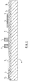
- Fig. 2 is a cross-sectional view through the line A-A of Fig. 1. This shows that the print head is built on to a ceramic substrate 12, which itself supported by a steel backing plate 11.
- lines 3 and 5 and connector pads 4 and 6 are placed on to the ceramic substrate by a screening process, and at the same time a portion of lines 7 extending from the point below the print bar position to a point above the upper print bar (Fig. 1) is also placed on the substrate.
- insulant 9, in the form of a glass layer is laid over leads 5.
- pads 8 are formed on layer 9 together with the remainder of leads 7 which extend to complete the lead 7 connections to the print bars.
- the print bars are mounted over the leads.
- Figs. 1 and 2 are highly magnified.
- a print head has been constructed with print bars 203 mm in length and with a spacing of 0.19 mm between their center lines. Adjacent connections to the print bars, that is, for example, the connections from lines 5 and 7 in Fig. 1 were 0.25 mm. Thus, the spacings between lines 5 and 7 were again 0.254 mm and between adjacent ones of lines 3, 0.508 mm. These dimensions provided an array of 1600 resistor elements requiring only 1202 connector lines.
- a number of different electrical drive arrangements may be envisaged for the print head. Basically, however, the best arrangement is selectively to drive lines 7 and to provide current return paths selectively on lines 3 and 5. Thus, if the left-most line 7 in Fig. 1 is driven, up to four of the print elements can be energised by selecting any, or all, of the leftmost pairs of lines 3 and 5 as current return paths. In order to reduce the instantaneous current requirements for the print head, the drive lines 7 may be driven either sequentially, line by line, or in blocks. Furthermore, if printing is performed on a continuously moving sheet, the current return lines 3 and 5 can be operated in timed relationship such that the print dots are formed along a substantially continuous line.
- print bar 2 is activated first, and shortly thereafter, at a time determined by the velocity of the sheet, print bar 1 is activated. This same principle applies, of course, when only portions of the print bars are activated to develop printed characters.
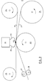
- Fig. 3 is a schematic diagram, not to scale, of a printer incorporating a print head of the type shown in Figs. 1 and 2.
- a web 20 of transfer material and a paper web 21 are sandwiched between the print head 22 and a backing roller 23.
- the transfer material comprises a mylar base carrying on its underside a layer of heat-transferrable ink.
- the transfer material is fed from a feed roller 24 to a take-up roller 25.
- the paper web is supplied from roll 26 and, after passing the print head is fed by a feed roller pair 27, 28 to an output device. This may be another roll or a sheet cutter and output tray.
- the print head 22 is connected by tape cables 29 and 30 to an electrical drive system 31.
- the webs of paper and transfer material are fed at the same velocity. As they pass between the print head and backing roller, the print bars in the head, which contact the mylar backing of the transfer web, are selectively energised to cause transfer of the ink to the paper web.
Landscapes
- Electronic Switches (AREA)
Applications Claiming Priority (2)
| Application Number | Priority Date | Filing Date | Title |
|---|---|---|---|
| US06/452,994 US4450342A (en) | 1982-12-27 | 1982-12-27 | Thermal print head |
| US452994 | 1989-12-19 |
Publications (2)
| Publication Number | Publication Date |
|---|---|
| EP0112473A2 true EP0112473A2 (de) | 1984-07-04 |
| EP0112473A3 EP0112473A3 (de) | 1986-03-12 |
Family
ID=23798804
Family Applications (1)
| Application Number | Title | Priority Date | Filing Date |
|---|---|---|---|
| EP83111137A Withdrawn EP0112473A3 (de) | 1982-12-27 | 1983-11-08 | Thermischer Druckkopf |
Country Status (3)
| Country | Link |
|---|---|
| US (1) | US4450342A (de) |
| EP (1) | EP0112473A3 (de) |
| JP (1) | JPS59120474A (de) |
Cited By (1)
| Publication number | Priority date | Publication date | Assignee | Title |
|---|---|---|---|---|
| EP0186059A3 (en) * | 1984-12-28 | 1987-03-04 | Wang Laboratories Inc. | Thermal print head |
Families Citing this family (2)
| Publication number | Priority date | Publication date | Assignee | Title |
|---|---|---|---|---|
| US4668962A (en) * | 1984-12-28 | 1987-05-26 | Wang Laboratories, Inc. | Thermal print head |
| JP4875415B2 (ja) * | 2006-06-27 | 2012-02-15 | 有限会社清田製作所 | コンタクトプローブ |
Family Cites Families (19)
| Publication number | Priority date | Publication date | Assignee | Title |
|---|---|---|---|---|
| US3453647A (en) * | 1965-03-24 | 1969-07-01 | American Standard Inc | Thermographic recording apparatus |
| US4039065A (en) * | 1972-08-15 | 1977-08-02 | Canon Kabushiki Kaisha | Thermal printer |
| US3955068A (en) * | 1974-09-27 | 1976-05-04 | Rockwell International Corporation | Flexible conductor-resistor composite |
| JPS5139131A (de) * | 1974-09-30 | 1976-04-01 | Shinshu Seiki Kk | |
| US3984844A (en) * | 1974-11-20 | 1976-10-05 | Hitachi, Ltd. | Thermal recording apparatus |
| US4030408A (en) * | 1975-01-21 | 1977-06-21 | Juichiro Ozawa | Thermal printer head |
| US3953708A (en) * | 1975-04-25 | 1976-04-27 | Xerox Corporation | Thermal printer using amorphous semiconductor devices |
| JPS52119946A (en) * | 1976-04-02 | 1977-10-07 | Hitachi Ltd | Drive system for thermal recording unit |
| SE431805B (sv) * | 1976-04-05 | 1984-02-27 | Oki Electric Ind Co Ltd | Termiskt skrivarhuvud |
| US4099046A (en) * | 1977-04-11 | 1978-07-04 | Northern Telecom Limited | Thermal printing device |
| US4074109A (en) * | 1977-07-15 | 1978-02-14 | Northern Telecom Limited | Thermal print bar |
| JPS54148542A (en) * | 1978-05-15 | 1979-11-20 | Hitachi Ltd | Drive method for heat sensitive recording head |
| JPS5953875B2 (ja) * | 1978-06-14 | 1984-12-27 | 株式会社東芝 | 感熱記録ヘツド |
| US4203119A (en) * | 1978-09-05 | 1980-05-13 | Northern Telecom Limited | Thermal printers |
| US4217480A (en) * | 1978-09-05 | 1980-08-12 | Northern Telecom Limited | Thermal print bar |
| US4242565A (en) * | 1979-06-05 | 1980-12-30 | Minnesota Mining And Manufacturing Company | Thermal print head |
| JPS57103862A (en) * | 1980-12-19 | 1982-06-28 | Fuji Xerox Co Ltd | Heat sensitive recording head |
| JPS57107864A (en) * | 1980-12-25 | 1982-07-05 | Mitani Denshi Kogyo Kk | Thermal head |
| JPS5816868A (ja) * | 1981-07-24 | 1983-01-31 | Fuji Xerox Co Ltd | 熱記録用印字ヘツド |
-
1982
- 1982-12-27 US US06/452,994 patent/US4450342A/en not_active Expired - Fee Related
-
1983
- 1983-10-19 JP JP58194486A patent/JPS59120474A/ja active Pending
- 1983-11-08 EP EP83111137A patent/EP0112473A3/de not_active Withdrawn
Cited By (1)
| Publication number | Priority date | Publication date | Assignee | Title |
|---|---|---|---|---|
| EP0186059A3 (en) * | 1984-12-28 | 1987-03-04 | Wang Laboratories Inc. | Thermal print head |
Also Published As
| Publication number | Publication date |
|---|---|
| US4450342A (en) | 1984-05-22 |
| EP0112473A3 (de) | 1986-03-12 |
| JPS59120474A (ja) | 1984-07-12 |
Similar Documents
| Publication | Publication Date | Title |
|---|---|---|
| US4099046A (en) | Thermal printing device | |
| US4636812A (en) | Thermal print head temperature control | |
| EP0112474A2 (de) | Temperaturüberwachung für Thermodruckkopf | |
| US4074109A (en) | Thermal print bar | |
| US4450342A (en) | Thermal print head | |
| US4636811A (en) | Thermal print head | |
| CA1073960A (en) | Thermal print bar | |
| EP0186059B1 (de) | Thermischer Druckkopf | |
| EP0028334A2 (de) | Verfahren und Vorrichtung, um Aufzeichnungsmaterial thermographisch zu bebildern | |
| EP0128760B1 (de) | Thermischer Aufzeichnungskopf | |
| US3870856A (en) | Thermal printing head | |
| US4668962A (en) | Thermal print head | |
| EP0633140B1 (de) | Thermo-Kopf | |
| JPS588673A (ja) | サ−マルヘツド | |
| JP2562880B2 (ja) | サ−マルヘツド | |
| JP2510850B2 (ja) | 厚膜サ−マルプリントヘツド | |
| EP0067953B1 (de) | Elektrothermischer Drucker | |
| JP2598270Y2 (ja) | 感熱プリンタ用サーマルヘッド | |
| JPS62204963A (ja) | プリンタ−用シリ−ズ型サ−マル印刷ヘツド | |
| JPH05131665A (ja) | サーマルヘツド | |
| JPS58131077A (ja) | サ−マルヘツド | |
| JP2749293B2 (ja) | サーマルヘッドの配線接続方法および配線接続構造 | |
| JPH0613222B2 (ja) | 高密度サ−マルラインヘツド | |
| JPS5839073B2 (ja) | ドツトプリンタノセイギヨホウホウ | |
| JPH07314755A (ja) | サーマルプリントヘッド |
Legal Events
| Date | Code | Title | Description |
|---|---|---|---|
| PUAI | Public reference made under article 153(3) epc to a published international application that has entered the european phase |
Free format text: ORIGINAL CODE: 0009012 |
|
| AK | Designated contracting states |
Designated state(s): DE FR GB IT |
|
| 17P | Request for examination filed |
Effective date: 19841029 |
|
| PUAL | Search report despatched |
Free format text: ORIGINAL CODE: 0009013 |
|
| AK | Designated contracting states |
Kind code of ref document: A3 Designated state(s): DE FR GB IT |
|
| 17Q | First examination report despatched |
Effective date: 19870615 |
|
| STAA | Information on the status of an ep patent application or granted ep patent |
Free format text: STATUS: THE APPLICATION IS DEEMED TO BE WITHDRAWN |
|
| 18D | Application deemed to be withdrawn |
Effective date: 19871027 |
|
| RIN1 | Information on inventor provided before grant (corrected) |
Inventor name: RAKES, JAMES MITCHELL Inventor name: WILLIAMS, ERROL RAY Inventor name: GOFF, WILLIE, JR. |