EP0112664A2 - Dispositif de pesage automatique et méthode - Google Patents
Dispositif de pesage automatique et méthode Download PDFInfo
- Publication number
- EP0112664A2 EP0112664A2 EP83307366A EP83307366A EP0112664A2 EP 0112664 A2 EP0112664 A2 EP 0112664A2 EP 83307366 A EP83307366 A EP 83307366A EP 83307366 A EP83307366 A EP 83307366A EP 0112664 A2 EP0112664 A2 EP 0112664A2
- Authority
- EP
- European Patent Office
- Prior art keywords
- articles
- volume
- weighing
- weight value
- density
- Prior art date
- Legal status (The legal status is an assumption and is not a legal conclusion. Google has not performed a legal analysis and makes no representation as to the accuracy of the status listed.)
- Granted
Links
Images




Classifications
-
- G—PHYSICS
- G01—MEASURING; TESTING
- G01G—WEIGHING
- G01G15/00—Arrangements for check-weighing of materials dispensed into removable containers
- G01G15/001—Volumetric pre-dispensing to an estimated weight; Gravimetric make-up device for target device
-
- G—PHYSICS
- G01—MEASURING; TESTING
- G01G—WEIGHING
- G01G19/00—Weighing apparatus or methods adapted for special purposes not provided for in the preceding groups
- G01G19/387—Weighing apparatus or methods adapted for special purposes not provided for in the preceding groups for combinatorial weighing, i.e. selecting a combination of articles whose total weight or number is closest to a desired value
- G01G19/393—Weighing apparatus or methods adapted for special purposes not provided for in the preceding groups for combinatorial weighing, i.e. selecting a combination of articles whose total weight or number is closest to a desired value using two or more weighing units
Definitions
- This invention relates to an automatic weighing apparatus and methods for weighing out articles for packaging in batches having respective weights held within preset allowable limits.
- Some articles such as cornflakes and potato chips, are subject to widely different degrees of swelling because of such processing conditions as applied temperature and material mixture. Such articles therefore differ in shape and size and vary greatly in apparent specific gravity. They also tend to crumble.
- the volume of the packaged product is too large or too small, even though the weight of the articles in the bag or package is equal to a target value or closest to the target value within preset limits.
- the change in volume of the packaged articles is in inverse proportion to the change in apparent specific gravity. Since the capacity of a package receiving the articles generally is fixed, too small a product volume in comparison with the package size gives the consumer the impression of a weight shortage.
- Embodiments of the present invention can provide an automatic weighing apparatus and method wherein both the weight and volume of articles in a package can be held within preset allowable limits.
- Such embodiments can be designed so as to provide an automatic weighing apparatus and method wherein, in weighing out articles to a fixed weight and then packaging the articles, the volume of the articles within the package is also fixed to avoid an unexpected volumetric excess when the packaging operation is carried out, thereby permitting the packaging process to proceed smoothly by preventing the articles from overflowing from the package.
- an automatic weighing system having means for detecting the density of weighed articles, and means for adjusting a target weight value on the basis of the density detected.
- the system further includes means for adjusting the size of individual articles on the basis of the detected density so as to compensate for unwanted changes therein, thereby to hold the apparent density substantially constant, or more nearly so than would otherwise be the case.
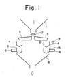
- Fig. 1 is a diagrammatic view showing the overall construction of a combinatorial weighing apparatus embodying the present invention.
- Articles to be weighed are supplied to each of n-number of circularly arrayed weighing stations from a supply chute 1.
- Each weighing station comprises a radial trough 3, a pool hopper 4 underlying the radial trough, a weighing hopper 5 underlying the pool hopper 4, and a weight sensor 6 provided on the weighing hopper 5.
- Each of the pool hoppers 4 is provided with a level sensor 7 for sensing the volume of the group of articles supplied by the corresponding radial trough 3. When these articles are released from the pool hopper 4 into the corresponding weighing hopper 5, the corresponding weight sensor 6 measures the weight of the article batch.
- the supply chute 1 supplies the articles to a dispersing table 2, which in turn disperses the articles radially outwardly to be ⁇ received by the underlying radial troughs 3.
- a dispersing table 2 which in turn disperses the articles radially outwardly to be ⁇ received by the underlying radial troughs 3.
- the radial troughs 3 supply the articles to the corresponding underlying pool hoppers 4
- the volume of the supplied articles is sensed.
- the articles are subsequently supplied to the corresponding underlying weighing hoppers 5 where the articles are weighed.
- the articles in weighing hoppers selected by a combinatorial computation are discharged from these weighing hoppers into a discharge chute 8, whence the articles are delivered to a packaging machine in order to be packaged.
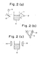
- Fig. 2 illustrates three specific examples of means for detecting the level of the articles with which the pool hoppers 4 are supplied.
- a laser beam emitted from a projector 9 is received by a light-receiving element 11 upon being reflected by a mirror 10.
- the mirror 10 and light receiving element 11 are rotated synchronously to move the reflected laser beam up and down to determine the level of the articles within the pool hopper 4. More specifically, the light-receiving element 11 is rotated back and forth by a stepping motor 12 in sync with the back-and-forth rotation of the mirror 10.
- the level of the article batch may be calculated from the rotational angle of the stepping motor 12 at such time.
- an image sensor 13 is employed as a light-receiving element. The sensor 13 is set so as to extend substantially vertically and is moved transversely along the side of the corresponding pool hopper 4 to detect the level of the article batch at individual points in the path of movement.
- a planar light beam projector 14 and a light-receiving element 15 are disposed to face each other on either side of the pool hopper 4, with the level of the article batch in the pool hopper being found from the quantity of light received by the element 15.
- a solar battery having a rectangular configuration can be employed as the light-receiving element 15, or an array of phototransistors can be used. An attenuation in the quantity of light from the projector 14 must be taken into account if the solar battery arrangement is adopted.
- two light-receiving elements are provided to serve as the element 15, one being for detecting a reference light quantity, the other being for actual measurement. Outputs from these two elements are applied to a differential amplifier the output whereof is subjected to an A/D conversion to obtain the article level.
- the volume of each article batch is calculated from the article level.
- the radial troughs 3 are rendered operational until the articles introduced into the corresponding pool hoppers 4 reach a certain level within the pool hopper.
- the period during which articles are supplied is somewhat arbitrary.
- the radial troughs 3 are always operated for a constant period of time irrespective of an excess volume of supplied articles. Since the period of time during which the articles are supplied is constant, it is easy to perform weighing periodically at a fixed cycle. However, the arrangement for detecting the level of articles supplied is more complicated.
- the first method is based on supplying the pool hoppers with a predetermined, fixed volume of the articles
- the second method is based on supplying the pool hoppers with articles for a predetermined period of time.
- both methods are applicable, the arrangement for computing the volume of supplied articles differs depending upon the method chosen.
- Fig. 3 is a block diagram illustrating an embodiment of the combinatorial weighing apparatus shown in Fig. 1 for a case where the apparatus is adapted to supply articles according to the first method described above.
- n-number of weighing machines Wl through Wn each comprise the weight sensor 6 and associated weighing hopper 5 of Fig. 1.
- All of the pool hoppers 4 are provided with corresponding level sensors 7.
- the radial troughs 3 operate to supply the corresponding pool hoppers 4 with articles, with operation continuing until the corresponding level sensors 7 issue a detection signal Sl.
- the detection signal Sl is delivered-to a timing control unit 38, described below, whereby the supply of articles is terminated.
- the volume of the articles supplied to each of the pool hoppers 4 attains a predetermined value each and every cycle.
- the weighing apparatus is of the combinatorial type, it is required that the quantity of articles supplied to the pool hoppers 4 be made to differ from one pool hopper to another. Therefore, the levels to be detected by the level sensors are different for each weighing station.
- a detecting unit 19 is provided with volume memories VMl through VMn which store the various levels in terms of volume.
- Each weighing machine Wl through Wn is adapted to respond to a discharge command signal S2 from a combination computing unit 20 by discharging its articles into the corresponding weighing hopper 5. Then, weighing hoppers 5 which are emptied after passage of a predetermined length of time are supplied with articles from the overlying pool hoppers 4, and the weights of the corresponding article batches are weighed by the weighing machines Wl through Wn, these producing outputs serving as weight data (weight values) w 1 through w n . These items of weight data enter the combination computing unit 20 where they are formed into combinations sequentially in accordance with combination patterns obtained as an output from a pattern generator 21.
- the computing unit 20 finds a single combination (“referred to as the "optimum combination” hereinafter) the total weight whereof is equal to a target value or closest to the target value.
- the optimum combination pattern and total weight value obtained are stored in memory, with the total weight value being delivered also to a comparator 22 and to a divider 23 in the detecting unit 19.
- the comparator 22 compares the total weight value with upper and lower limit values obtained from an allowable range setting unit 24, thereby to check whether the total weight value falls within preset allowable limits. If it does, the comparator 22 delivers a signal S3 indicative of the fact to the combination computing unit 20, which responds by applying the discharge command signal S2 to those weighing machines Wl through Wn corresponding to the optimum combination pattern stored in the computing unit 20.
- the discharge command signal S2 is applied also to the detecting unit 19.
- the signal which acts as a read signal, enters those volume memories VM1 through VMn that correspond to the weighing machines Wl through Wn selected by the optimum combination.
- Volume data v l through v read out of these volume memories in response to the signal S2 are applied to an adder 25, where the volume of the article batches corresponding to the optimum combination is computed and applied to the divider 23.
- the density of the articles is computed from the volume data and total weight value, which is the total of the combined weight values constituting the optimum combination, as described above.
- the density data obtained in this fashion is sampled once per cycle or one every several cycles so that the average density may be computed by an average density calculating device 26.
- a target weight adjusting unit 27 increases or decreases the aforementioned target weight value in the weighing section within the preset allowable limits in such a manner that the volume of the articles charged into a prescribed packaging vessel tends to remain substantially constant. More specifically, the target weight value, namely the total weight of the article batch desired to be weighed out by the apparatus, is preset and stored in the target value setting unit 28. In a case where the number of times the average density is sampled is less than a predetermined number, the average density calculating device 26 produces a control signal S6 which holds a gate 29 in the target t weight adjusting unit 27 closed. As a result, no change in the target weight value takes place.
- the initial value namely the value within the target value setting unit 28, is delivered to the combination computing unit 20 through an adder 35 without being adjusted.
- the target weight value is adjusted within the target weight adjusting unit 27 on the basis of the average density.
- the criterion for judging the reliability of the average density may be understood as being a certain fixed number of weighing operations in a case where all weighing stations are provided with level sensors 7, as in the arrangement of Fig. 3. In other words, the number of weighing cycles are counted starting from the initial cycle. When the counted number reaches the fixed number, the average density is deemed to have the desired reliability. In a case where only some of the weighing stations are provided with the level sensors 7, as in a later embodiment, the average density is judged to be reliable when a predetermined number of data have enterd a shift register located within the average density calculating device 26.
- the target weight value is adjusted in the target weight adjusting unit 27 as described above.
- the averable density from the average density calculating device 26 is applied to a comparator 30 in the target weight adjusting unit 27.
- the comparator 30 compares the average density with a value stored in an upper limit density memory 32 and disables the gate 29 if the average density is found to be less than the stored value.
- the upper limit density memory 32 is a device in which there is set and stored the upper limit value of the proper density, namely the upper limit of a density for which processing to change the target value need not be executed. If the average density does not exceed this upper limit, then operation proceeds on the assumption that the average density is of the proper value. No processing to adjust the target weight value is carried out.
- an adder/subtractor 31 computes the difference between the average density and the value in the upper limit density memory 32, and applies the computed difference to a multiplier 33.
- the latter computes the product between the output of the adder/subtractor 31 and a value in an adjustment increment setting device 34, and applies the product to an adder 35 through a gate 29.
- the adjustment increment setting device 34 stores a certain constant for changing the target weight value in step-by-step fashion in accordance with density. For example, to change the target weight value by 0.2 g with respect to a density of 0.1 g/cm 3 , "2" is stored in the device 34.
- An adjustment range setting device 36 stores an allowable range within which it is permissible to change the target weight value. For example, if 100 g is the lower limit and it is permissible to change the target weight value up to 105 g, then a value corresponding to 5 g is stored in the device 36. The value in the multiplier 33 and the value in the adjustment range setting device 36 are compared in a comparator 37. If the former is found to be larger, the value in the adjustment range setting device 36, namely the upper limit value of the allowable range, is applied to the adder 35 through the gate 29.
- the value in the multiplier 33 is applied to the adder 35 through the gate 29.
- the adder 35 receives as inputs the value set in the target value setting unit 28 and either the value from the multiplier 33 or the value from the adjustment range setting device 36.
- the sum computed by the adder 35 serves as the target value of the combinatorial weighing operation.
- the combination computing unit 20 selects, from among the combinations of weight value data wl through w n , the optimum . combination, namely the combination giving a total weight value equal or closest to this target value.
- the discharge command signal S2 which is delivered to those of the weighing machines Wl through Wn constituting the optimum combination from the combination computing unit 20, is simultaneously applied to a timing control unit 38 which, in response, delivers a discharge command signal S4 and an operation command signal S5, described below, to the pool hoppers 4 and radial troughs 3, respectively, the operating periods whereof are controlled thereby. More specifically, the discharge command signal S2 is applied to the weighing hoppers 5 of those weighing machines Wl through Wn selected by the optimum combination from the combination computing unit 20, and to the timing control unit 38.
- the timing control unit 38 sends the discharge command signal S4 to the pool hoppers 4 of the weighing machines selected by the optimum combination and then, upon passage of a fixed period of time, sends the operation command signal S5 to the radial troughs 3 of the weighing machines selected by the optimum combination.
- the weighing hoppers 5 of the selected weighing machines discharge their articles and are left empty owing to the discharge signal S2, after which the pool hoppers 4 corresponding to these emptied weighing hoppers 5 discharge their articles in response to the discharge command signal S4 to resupply the weighing hoppers.
- the timing control unit 38 which responds by terminating the delivery of the operation command signal S5 applied to the radial troughs 3, so that the troughs stop supplying articles.
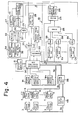
- Fig. 4 is a block diagram illustrating an embodiment of the combinatorial weighing apparatus shown in Fig. 1 for a case where the apparatus is adapted to supply articles according to the second method described above, namely the method based on supplying the pool hoppers 4 with articles for a predetermined period of time.
- all of the pool hoppers 4 are provided with the level sensors 7 for detecting the height of the articles supplied to the corresponding pool hoppers 4 by operating the corresponding radial troughs 3 for a fixed period of time.
- the detected levels are applied to corresponding arithmetic units Cl through Cn each of which computes and stores the volume of the articles supplied to the corresponding pool hopper 4.
- the combination computing unit 20 selects the weighing machines which correspond to the optimum combination, and the total of the weights contained in the weighing machines selected is delivered to the comparator 22 and divider 23. If the comparator 22 finds the total weight value to be within the preset allowable limits, the combination computing unit 20 applies the discharge command signal S2 to those of the weighing machines Wl through Wn constituting the optimum combination, and to the timing control unit 38.
- the discharge command signal S2 is applied to gate circuits 39 in the detecting unit 19 to open these circuits for delivering the outputs of the corresponding arithmetic units Cl through Cn.
- Each output which is an item of data indicating the computed volume of the articles supplied to the corresponding pool hopper 4 of the corresponding weighing machine in the optimum combination, is applied to the adder 25 through the corresponding gate 39.
- the divider 23 computes the density of the articles from the total of the weight values in the optimum combination and from the summed volume data provided by the adder 25.
- the target weight value is adjusted by the target weight adjusting unit 27 based on the average density computed in the average density computing device 26 on the basis of the density data.
- the target weight value namely the total weight of the article batch desired to be weighed out by the apparatus, is preset and stored in the target value setting unit 28.
- the target weight value adjustment is performed, if necessary, when the number of data for computing average density reaches a predetermined value to assure that the average density is reliable.
- the initially set value namely the value in the target value setting unit 28, is used as the target weight value.
- the average density is delivered from the average density calculating device 26 to the target weight adjusting unit 27, where the target weight value is adjusted. Thereafter, the target weight value is applied to the combination computing unit 20 so that combinations may be computed based on this value.
- the mechanism for adjusting the target weight value is the same as in the arrangement of Fig. 3.
- the comparator 30 compares the average density with the value in the upper limit density memory 32. If the average density does not exceed the upper limit density, processing for changing the target value is not performed. If the upper limit density is exceeded, however, then the adder/subtractor 31 computes the difference between the average density and the value stored in the upper limit density memory 32, with the result of the computation being delivered to the multiplier 33 at the same time.
- the multiplier 33 multiplies the output of the adder/subtractor 31 by the value in the adjustment increment setting device 34 and delivers the product, which is compared in the comparator 37 with the value in the adjustment range setting device 36. The smaller of the two values is thereafter delivered to the adder 35 through the gate 29.
- the adder 35 adds the adjustment factor to the initially set value, namely the value in the target value setting unit 28, with the output of the adder serving as the target value for a combinatorial computation.
- the combination computing unit 20 selects whichever of the weighing machines Wl through Wn make up the optimum combination.
- the timing control unit 38 sends the discharge command signal S4 to the pool hoppers 4 of the weighing machines selected by the optimum combination, and sends the operation command signal S5 to the corresponding radial troughs 3, thereby controlling the operating time of these units.
- the operation command signal S5 for the radial troughs 3 is delivered through a drive control unit 45 to control the period of time during which the radial trougs 3 operate.
- the radial troughs 3 supply articles to the corresponding pool hoppers 4 while the operating time of the troughs is controlled by the drive control unit 45 in such a manner that each trough'operates for a length of time different from the other troughs.
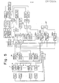
- Fig. 5 is a block diagram of an arrangement wherein only some of the of pool hoppers 4 in the embodiment of Fig. 3 are provided with the level sensors 7. Specifically, a level sensor is provided on m-number of the pool hoppers 4, where m ⁇ n. With such an arrangement, the total of a weight combination computed by the combination computing unit 20 cannot be used to compute density. Therefore, volume memories VM1, VM2,... VMm are provided for corresponding ones of the m pool hoppers 4 equipped with the respective level sensors 7, and weight memories WM1, WM2,... WMm are separately provided for the weighing machines Wl, W2,... corresponding to these pool hoppers. Among the weighing machines W1, W2...
- the weight value memories WM1, WM2,... WMm are provided in similar fashion, and operation proceeds in manner similar to that described above.
- Fig. 6 is a diagrammatic view showing the construction of the combinatorial weighing apparatus of Fig. 1 when additionally provided with means, including a conditioner 40, for shaping weighed articles into a fixed volume.
- the shaping means comprises a collecting chute 8', the conditioner 40 adapted to reciprocate inside a cylinder 8" formed at the lower end portion of the chute 8', a ring shutter 41 partitioning the upper part of the chute 8' from the lower part thereof, a gate plate 42, and a control unit 43 (Fig. 8) for controlling the ring shutter 41, conditioner 40 and gate plate 42.
- the gate plate 42 is adapted to open and close a discharge port at the lower end of the collecting chute 8' in response to a command from the control unit 43.
- the conditioner 40 and ring shutter 41 are adapted to be driven up and down by a suitable drive mechanism controlled by the control unit 43.
- the gate plate 42 is made to close the chute discharge port, the ring shutter 41 is moved to its lowermost position, and the conditioner 40 is moved to its uppermost position, as shown by the solid lines in Fig. 7.
- two batches of articles selected by respective optimum combinations and discharged successively from the weighing hoppers may be separated within the collecting chute 8' by the ring shutter 41, one batch being collected below the ring shutter, the other above.
- the conditioner 40 is lowered to shape or compress the lower batch of articles into a fixed volume irrespective of average density.
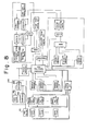
- Fig. 8 is a block diagram illustrating an embodiment of the combinatorial weighing apparatus shown in Fig. 6 for a case where the apparatus is adapted to supply articles according to the first method described above, namely the method in which the pool hoppers are supplied with a predetermined, fixed volume of the articles.
- the embodiment shown in Fig. 8 is obtained by providing the arrangement of Fig. 3 with the volume shaping means 44 described above. Articles weighed out as described hereinabove are shaped into a predetermined, fixed volume before being delivered to a packaging machine.
- the density of the articles in the weighing section of the combinatorial weighing apparatus is detected, and an adjustment unit is provided for adjusting the size of individual articles based on the detected density in such a manner that the density of the articles takes on a substantially constant, predetermined value.
- Fig. 9 is a diagrammatic view showing' the construction of a combinatorial weighing apparatus obtain by providing the apparatus of Fig. 1 with the aforementioned adjustment unit. The following discussion will deal primarily with the adjustment unit. Other portions corresponding to those shown in Fig. 1 are designated by like reference characters and are not described again in detail.
- a supply chute 201 is disposed above the weighing apparatus at the center thereof and receives articles delivered by a bucket conveyor 203.
- the chute 201 is adapted to supply these articles to each of the weighing stations of the apparatus.
- a crusher 202 such as a screw, for crushing the articles delivered thereto.
- the crusher 202 is operated by a motor 231 controlled on the basis of a control signal received from a controller 232, described below.
- the size of the individual articles is adjusted by the crushing action of the crusher 202.
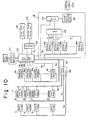
- Fig. 10 is a block diagram illustrating an embodiment of the combinatorial weighing appparatus shown in Fig. 9.
- the apparatus which is provided with the unit for adjusting the size of the individual articles, operates in accordance with the first method based on supplying the pool hoppers with a predetermined, fixed volume of the articles.
- the discussion will focus on the size adjusting operation, with the descriptions of the weighing and density detecting sections being deleted to avoid prolixity.
- the discharge command signal S2 is applied also to the detecting unit 19.
- the signal which acts as a . read signal, enters those volume memories VM1 through VMn that correspond to the weighing machines Wl through Wn selected by the optimum combination.
- Volume data v l through v n read out of these volume memories in response to the signal S2 are applied to an adder 25, where the volume of the article batches corresponding to the optimum combination is computed and applied to the divider 23.
- the density of the articles is computed from the volume data and total weight value, which is the total of the combined weight values constituting the optimum combination received from the combination computing unit 20.
- the density data obtained in this fashion is sampled once per cycle or one every several cycles so that the average density may be computed by an average density computing device 26.
- the adjustment unit 230 adjusts the size of the individual articles in such fashion that the density of the articles becomes substantially constant.
- the adjustment unit 230 comprises the supply chute 201, the crusher 202 provided inside the supply chute, the motor 231 for driving the crusher, and the controller 232 for controlling the motor.
- the crusher 202 is driven continuously and variably by the motor 221, the rotation whereof is regulated by the controller 232 based on the average density of the articles. This enables individual articles to be adjusted in size.
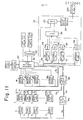
- Fig. 11 is a block diagram illustrating another embodiment of the combinatorial weighing appparatus shown in Fig. 9.
- the apparatus operates in accordance with the second method based on supplying the pool hoppers with articles for a predetermined, fixed period of time. Portions corresponding to those shown in the block diagram of Fig. 4 are designated by like reference characters and are not described in detail again.
- all of the pool hoppers 4 are provided with the level sensors 7 for detecting the height of the articles supplied to the corresponding pool hoppers 4 by operating the corresponding radial troughs 3 for a fixed period of time.
- the detected levels are applied to corresponding arithmetic units Cl through Cn each of which computes and stores the volume of the articles supplied to the corresponding pool hopper 4.
- the combination computing unit 20 selects the weighing machines which correspond to the optimum combination, and the total of the weights contained in the weighing machines selected is delivered to the comparator 22 and divider 23. If the comparator 22 finds the total weight value to be within the preset allowable limits, the combination computing unit 20 applies the discharge command signal S2 to those of the weighing machines Wl through Wn constituting the optimum combination, and to the timing control unit 38.
- the discharge command signal S2 is applied to gate circuits 39 in the detecting unit 19 to open these circuits for delivering the outputs of the corresponding arithmetic units Cl through Cn.
- Each output which is'an item of data indicating the computed volume of the articles supplied to the corresponding pool hopper 4 of the corresponding weighing machine in the optimum combination, is applied to the adder 25 through the corresponding gate 39. Then, as in Fig. 3, the divider 23 computes the density of the articles from the total of the weight values in the optimum combination and from the summed volume data provided by the adder 25. The individual articles are adjusted in size by the adjustment unit 230 based on the average density computed in the average density computing device 26 on the basis of the density data.
- Fig. 12 is a block diagram of an arrangement wherein only some of the of pool hoppers 4 in the embodiment of Fig. 10 are provided with the level sensors 7. Specifically, a level sensor is provided on m-number of the pool hoppers 4, where m ⁇ n. With such an arrangement, the total of a weight combination computed by the combination computing unit 20 cannot be used to compute density. Therefore, volume memories VM1, VM2,... VMm are provided for corresponding ones of the m pool hoppers 4 equipped with the respective level sensors 7, and the detecting unit 19 is provided with weight memories WMl, WM2,... WMm for respective weighing machines Wl, W2,... corresponding to these pool hoppers. Among the weighing machines Wl, W2...
- the target weight can be increased or decreased, based on the detected density of the articles, within preset allowable limits in such a manner that the'volume of the articles charged into a package takes on a substantially constant, predetermined value.
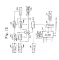
- the construction of the target weight adjusting unit is illustrated in the block diagram of Fig. 13.
- the target weight setting unit 28 stores a set target value indicative of the weight of the articles desired to be weighed out by the combinatorial weighing apparatus. If the apparatus is to weigh out 100 g, for example, then a value corresponding to 100 g is set in the unit 28.
- the adjustment of the target weight value in the adjusting unit is performed when the number of data for computing average density reaches a predetermined value to assure that the average density is reliable. Specifically, in a case where the number of times the average density is sampled is less than a predetermined number, an average density calculating device 329 produces a control signal S6' which holds a gate 340 closed. As a result, no change in the target weight value takes place.
- the initial value namely the value within the target value setting unit 28, is delivered to the combination computing unit 20 through an adder 343 without being adjusted.
- the criterion for judging the reliability of the average density may be understood as being a certain fixed number of weighing operations in a case where all weighing stations are provided with level sensors 7.
- the number of weighing cycles are counted starting from the initial cycle.
- the average density is deemed to have the desired reliability.
- the average density is judged to be reliable when a predetermined number of data have entered a shift register located within the average density calculating device 329.
- the target weight value is adjusted in the target weight adjusting unit as described above. Specifically, the averable density from the average density calculating device 329 is applied to a comparator 339.
- the comparator 339 compares the average density with a value stored in an upper limit density memory 338 and disables the gate 340 if the average density is found to be less than the stored value.
- the upper limit density memory 338 is a device in which there is set and stored the upper limit value of the proper density, namely the upper limit of a density for which processing to change the target value need not be executed. If the average density does not exceed this upper limit, then operation proceeds on the assumption that the average density is of the proper value. No processing to adjust the target weight value is carried out. When the average density exceeds the upper limit, however, the target weight value is adjusted on the basis of the average density in the the following manner.
- an adder/subtractor 341 computes the difference between the average density and the value in the upper limit density memory 338, and applies the computed difference to a multiplier 342.
- the latter computes the product between the output of the adder/subtractor 341 and a value in an adjustment increment setting device 337, and applies the product to an adder 343 through the gate 340.
- the adjustment increment setting device 337 stores a certain constant for changing the target weight value in step-by-step fashion in accordance with density. For example, to change the target weight value by 0.2 g with respect to a density of 0.1 g/cm 3 , "2" is stored in the device 337.
- An adjustment range setting device 336 stores an allowable range within which it is permissible to change the target weight value. For example, if 100 g is the lower limit and it is permissible to change the target weight value up to 105 g, then a value corresponding to 5 g is stored in the device 336. The value in the multiplier 342 and the value in the adjustment range setting device 336 are compared in a comparator 344.
- the value in the adjustment range setting device 336 namely the upper limit value of the allowable range
- the value in the multiplier 342 is applied to the adder 343 through the gate 340.
- the adder receives as inputs the value set in the target value setting unit 28 and either the value from the multiplier 342 or the value from the adjustment range setting device 336.
- the sum computed by the adder 343 serves as the target value of the combinatorial weighing operation.
- the combination computing unit 20 selects, from among the combinations of weight value data w 1 through w n, the optimum combination, namely the combination giving a total weight value equal or closest to this target value.
- the target weight value is increased or decreased within preset allowable limits by the target weight adjusting unit in such fashion that the volume of the articles charged into a packaging vessel takes on a substantially constant value.
- the construction and operation of the weighing section, detecting unit and adjustment unit are as described hereinabove.
- an embodiment of the invention aa described hereinabove makes it possible to hold both the weight and volume of each article batch within preset allowable limits. Therefore, when weighing out and packaging articles in batches each of which has a fixed weight, the volume of each batch within the packaging vessels will also be fixed. This makes it possible to avoid an unexpected volumetric excess caused by a variation in apparent specific gravity when the packaging operation is carried out, thereby preventing the articles from overflowing from the package.
- a batch of articles of a fixed weight will always have a volume suited to the specified capacity of the packaging vessel, thereby making it possible to prevent too small a product volume and, hence, the impression of a weight shortage.
- too large a product volume can be avoided to preclude an improper seal and an obstruction to the packaging process caused by overflowing of articles from the package.
Landscapes
- Physics & Mathematics (AREA)
- General Physics & Mathematics (AREA)
- Basic Packing Technique (AREA)
- Weight Measurement For Supplying Or Discharging Of Specified Amounts Of Material (AREA)
Applications Claiming Priority (4)
| Application Number | Priority Date | Filing Date | Title |
|---|---|---|---|
| JP212954/82 | 1982-12-03 | ||
| JP21295482A JPS59102123A (ja) | 1982-12-03 | 1982-12-03 | 自動計量装置 |
| JP21287182A JPS59102122A (ja) | 1982-12-04 | 1982-12-04 | 自動計量装置 |
| JP212871/82 | 1982-12-04 |
Publications (3)
| Publication Number | Publication Date |
|---|---|
| EP0112664A2 true EP0112664A2 (fr) | 1984-07-04 |
| EP0112664A3 EP0112664A3 (en) | 1986-01-08 |
| EP0112664B1 EP0112664B1 (fr) | 1990-01-24 |
Family
ID=26519472
Family Applications (1)
| Application Number | Title | Priority Date | Filing Date |
|---|---|---|---|
| EP83307366A Expired - Lifetime EP0112664B1 (fr) | 1982-12-03 | 1983-12-02 | Dispositif de pesage automatique et méthode |
Country Status (4)
| Country | Link |
|---|---|
| US (1) | US4548286A (fr) |
| EP (1) | EP0112664B1 (fr) |
| AU (1) | AU558328B2 (fr) |
| DE (1) | DE3381150D1 (fr) |
Cited By (8)
| Publication number | Priority date | Publication date | Assignee | Title |
|---|---|---|---|---|
| GB2147111A (en) * | 1983-09-28 | 1985-05-01 | Yamato Scale Co Ltd | Combination weighing with volumetric metering |
| FR2591334A1 (fr) * | 1985-12-05 | 1987-06-12 | Yamato Scale Co Ltd | Balance de combinaison |
| FR2593601A1 (fr) * | 1986-01-29 | 1987-07-31 | Yamato Scale Co Ltd | Dispositif pour alimenter en produits une balance de combinaison |
| FR2598223A1 (fr) * | 1986-05-02 | 1987-11-06 | Yamato Scale Co Ltd | Systeme de pesee automatique |
| FR2598222A1 (fr) * | 1986-05-02 | 1987-11-06 | Yamato Scale Co Ltd | Dispositif de mesure de densite apparente de produits delivres a une machine de pesee |
| EP0464697A3 (en) * | 1990-07-03 | 1992-05-27 | Colortronic Gmbh | Process and device for dosing |
| EP3101398A4 (fr) * | 2014-01-30 | 2017-02-08 | Ishida Co., Ltd. | Appareil de pesage de combinaison |
| EP3620759A1 (fr) * | 2018-09-04 | 2020-03-11 | ISHIDA CO., Ltd. | Dispositif de pesage |
Families Citing this family (35)
| Publication number | Priority date | Publication date | Assignee | Title |
|---|---|---|---|---|
| FI72475C (fi) * | 1985-02-08 | 1987-06-08 | Waertsilae Oy Ab | Foerfarande foer anordning av rullar, i synnerhet pappersrullar till en foerpackning laemplig foer leverans. |
| US4796782A (en) * | 1985-10-30 | 1989-01-10 | Automation, Inc. | Ink monitor system |
| US4921132A (en) * | 1985-10-30 | 1990-05-01 | Automation, Inc. | Ink motor system |
| US4720961A (en) * | 1986-01-13 | 1988-01-26 | Conagra, Inc. | Chicken sorting device |
| US4657094A (en) * | 1986-04-07 | 1987-04-14 | Package Machinery Company | Fill height detector in weighing and packaging system |
| US4718217A (en) * | 1986-08-04 | 1988-01-12 | Pneumatic Scale Corporation | Settling systems for bag-in-box machines |
| US4827697A (en) * | 1986-08-04 | 1989-05-09 | Pneumatic Scale Corporation | Settling systems for bag-in-box machines |
| US4825623A (en) * | 1986-08-04 | 1989-05-02 | Pneumatic Scale Corporation | Cyclically operable apparatus for forming and filing bags |
| JP2601649B2 (ja) * | 1986-12-10 | 1997-04-16 | 大和製衡 株式会社 | 金属検出器付き計量包装装置 |
| US4905779A (en) * | 1987-06-01 | 1990-03-06 | Yamato Scale Company, Limited | Operation condition collator and methods |
| US4898254A (en) * | 1988-07-11 | 1990-02-06 | Sanyo Electric Co., Ltd. | Electronic weighing apparatus |
| US5004093A (en) * | 1989-11-08 | 1991-04-02 | Charles Packaging Corporation | Straight line sorting and/or fill-to-weigh machine |
| US5092414A (en) * | 1989-11-08 | 1992-03-03 | Charles Packaging Corporation | Straight line fill-to-weight machine |
| DE3938220A1 (de) * | 1989-11-17 | 1991-05-23 | Benz & Hilgers Gmbh | Verfahren und vorrichtung zum verpacken von pastoesen produkten, wie suppenpasten, margarine, butter oder dgl. in form von paeckchen, wuerfeln oder dgl. |
| US5174821A (en) * | 1989-12-12 | 1992-12-29 | Taisei Corporation | Hydraulic composition, formed products therefrom and segregation reduction agent for hydraulic substances |
| DE4013246C2 (de) * | 1990-04-26 | 2001-05-23 | Harton Anlagentechnik Gmbh | Anlage zur Bestimmung des Raumgewichtes einer Schüttgutfraktion |
| GB9017797D0 (en) * | 1990-08-14 | 1990-09-26 | Ilapak Limited | Packaging method and apparatus |
| US5174094A (en) * | 1991-10-24 | 1992-12-29 | Powell Machinery, Inc. | Automatic bagging |
| CA2129625A1 (fr) * | 1992-12-14 | 1994-06-23 | Steven C. Maglecic | Emballeuse de frites sous vide |
| DE4335074C1 (de) * | 1993-10-14 | 1994-11-03 | Multipond Gmbh | Vorrichtung zum Beschicken einer einer Verpackungseinrichtung vorgeschalteten Wägeeinrichtung mit zerbrechlichen Lebensmitteln unregelmäßiger Größe und ähnlichen Produkten, insbesondere Kartoffelchips |
| US5571067A (en) * | 1993-11-19 | 1996-11-05 | Ranpak Corp. | Cushioning conversion machine including a length measuring device |
| US6524230B1 (en) * | 1994-07-22 | 2003-02-25 | Ranpak Corp. | Packing material product and method and apparatus for making, monitoring and controlling the same |
| DE776760T1 (de) * | 1994-07-22 | 1997-11-20 | Ranpak Corp., Concord Township, Ohio | Polsterumwandlungsmaschine |
| US5897478A (en) | 1994-07-22 | 1999-04-27 | Ranpak Corp. | Cushioning conversion machine and method using encoded stock material |
| US5481855A (en) * | 1994-09-27 | 1996-01-09 | Yuyama; Shoji | Tablet packing device and method for controlling the same |
| DE19828530A1 (de) * | 1998-06-26 | 1999-12-30 | Bilfinger Berger Bau | Verfahren und Vorrichtung zur Ermittlung der Dichte von Suspensionen |
| EP1508278A4 (fr) * | 2002-05-29 | 2010-04-21 | Ishida Seisakusho | Dispositif d'assaisonnement et systeme de production de produit a l'aide dudit dispositif |
| CA2504124C (fr) * | 2002-11-01 | 2013-01-08 | Ranpak Corp. | Systemes d'emballage a mesure du volume a remplir |
| US20050058016A1 (en) * | 2003-09-15 | 2005-03-17 | Smith Morris E. | Method to blend two or more fluids |
| US20080091299A1 (en) * | 2006-10-13 | 2008-04-17 | Ishida Co., Ltd. | Weighing and packaging system and setting input device for product processing system |
| US7439457B1 (en) | 2007-05-11 | 2008-10-21 | John E Meschter | Apparatus for determining relative density of produce using weighing and size measuring |
| DE102008020256A1 (de) * | 2008-04-22 | 2009-10-29 | Haver & Boecker Ohg | Packanlage |
| GB201206983D0 (en) * | 2012-04-20 | 2012-06-06 | Ishida Europ Ltd | Method and apparatus for use in a food packaging system |
| CN107209049B (zh) * | 2015-02-10 | 2020-07-24 | 株式会社石田 | 输送装置及组合计量装置 |
| JP6586159B2 (ja) * | 2015-03-06 | 2019-10-02 | 株式会社イシダ | ミックス計量装置 |
Family Cites Families (8)
| Publication number | Priority date | Publication date | Assignee | Title |
|---|---|---|---|---|
| DE1424089B1 (de) * | 1959-10-07 | 1969-09-11 | Hesser Ag Maschf | Volumetrisch arbeitende Dosiermaschine mit selbsttaetiger Gewichtskorrektur |
| CH385712A (de) * | 1960-06-18 | 1964-12-15 | Hesser Ag Maschf | Abfüllmaschine |
| GB1093111A (en) * | 1963-09-20 | 1967-11-29 | Coal Industry Patents Ltd | Improvements in apparatus for delivering divided material |
| US3703795A (en) * | 1971-05-28 | 1972-11-28 | Mastic Corp | Building siding units |
| GB1495752A (en) * | 1974-03-12 | 1977-12-21 | Amf Inc | Continuous measurement of the bulk density of particulate material such as cut tobacco |
| IT1048550B (it) * | 1975-10-29 | 1980-12-20 | Acma Spa | Apparecchiatura per il controllo e la regolazione del peso di dosi di prodotti scorrevoli in teste do satrici rotanti ad elementi volume trici telescopici |
| JPS5946821A (ja) * | 1982-09-11 | 1984-03-16 | Ishida Scales Mfg Co Ltd | 組み合せ計量方法 |
| US4537229A (en) * | 1982-09-16 | 1985-08-27 | Kabushiki Kaisha Ishida Koki Seisakusho | Automatic weighing apparatus and method |
-
1983
- 1983-12-02 EP EP83307366A patent/EP0112664B1/fr not_active Expired - Lifetime
- 1983-12-02 US US06/557,337 patent/US4548286A/en not_active Expired - Lifetime
- 1983-12-02 DE DE8383307366T patent/DE3381150D1/de not_active Expired - Lifetime
- 1983-12-02 AU AU21912/83A patent/AU558328B2/en not_active Expired
Cited By (12)
| Publication number | Priority date | Publication date | Assignee | Title |
|---|---|---|---|---|
| GB2147111A (en) * | 1983-09-28 | 1985-05-01 | Yamato Scale Co Ltd | Combination weighing with volumetric metering |
| FR2591334A1 (fr) * | 1985-12-05 | 1987-06-12 | Yamato Scale Co Ltd | Balance de combinaison |
| FR2593601A1 (fr) * | 1986-01-29 | 1987-07-31 | Yamato Scale Co Ltd | Dispositif pour alimenter en produits une balance de combinaison |
| FR2598223A1 (fr) * | 1986-05-02 | 1987-11-06 | Yamato Scale Co Ltd | Systeme de pesee automatique |
| FR2598222A1 (fr) * | 1986-05-02 | 1987-11-06 | Yamato Scale Co Ltd | Dispositif de mesure de densite apparente de produits delivres a une machine de pesee |
| GB2190207A (en) * | 1986-05-02 | 1987-11-11 | Yamato Scale Co Ltd | Automatic weighing system |
| GB2190207B (en) * | 1986-05-02 | 1990-02-21 | Yamato Scale Co Ltd | Automatic weighing system |
| EP0464697A3 (en) * | 1990-07-03 | 1992-05-27 | Colortronic Gmbh | Process and device for dosing |
| EP3101398A4 (fr) * | 2014-01-30 | 2017-02-08 | Ishida Co., Ltd. | Appareil de pesage de combinaison |
| US10151622B2 (en) | 2014-01-30 | 2018-12-11 | Ishida Co., Ltd. | Combination weighing device for weighing articles conveyed to a hopper |
| EP3620759A1 (fr) * | 2018-09-04 | 2020-03-11 | ISHIDA CO., Ltd. | Dispositif de pesage |
| US10962403B2 (en) | 2018-09-04 | 2021-03-30 | Ishida Co., Ltd. | Weighing device with an article supply conveyor that runs for different lengths of time depending on the detection of an article hanging from the end |
Also Published As
| Publication number | Publication date |
|---|---|
| US4548286A (en) | 1985-10-22 |
| EP0112664A3 (en) | 1986-01-08 |
| AU2191283A (en) | 1984-06-07 |
| EP0112664B1 (fr) | 1990-01-24 |
| DE3381150D1 (de) | 1990-03-01 |
| AU558328B2 (en) | 1987-01-29 |
Similar Documents
| Publication | Publication Date | Title |
|---|---|---|
| US4548286A (en) | Combinatorial weighing method and apparatus with volume and density sensing | |
| US5753866A (en) | Combinational weigher | |
| EP0103475B1 (fr) | Procédé et appareil de pesage et d'emballage | |
| US4534428A (en) | Vibratory feeder control for a weighing system | |
| US4418771A (en) | Method and apparatus for combination weighing | |
| US4661917A (en) | Mixing combinatorial counting and weighing method, and apparatus therefor | |
| EP0097532B1 (fr) | Dispositif de pesage combinatoire | |
| EP0074260A2 (fr) | Dispositif de pesage combinatoire | |
| US5894111A (en) | Quantitative charging apparatus | |
| EP1347870B1 (fr) | Systeme permettant d'alimenter en portions de materiau une machine de moulage par injection | |
| US4967856A (en) | Combination weighing machine | |
| US4537229A (en) | Automatic weighing apparatus and method | |
| US4522274A (en) | Combinatorial weighing method | |
| EP0084962B1 (fr) | Dispositif de pesage | |
| US5756939A (en) | Combinational weighing machine | |
| US4669557A (en) | Weighing apparatus | |
| US4499961A (en) | Combinatorial weighing apparatus with check weigher | |
| US4569406A (en) | Combination weighing machine having volume confining function | |
| US4721173A (en) | Automatic weighing system with density ratio control of volume | |
| EP1424542B1 (fr) | Dispositif de pesage combinatoire | |
| EP0103476B1 (fr) | Méthode de pesage combinatoire et dispositif y relatif | |
| US4538692A (en) | Method and apparatus for combination weighing with multiple storage cups for each scale hopper | |
| US4630695A (en) | Combinatorial weigher employing double group split logic | |
| EP0911617B1 (fr) | Procédé pour peser des éclats ou de la poudre | |
| EP0100223A2 (fr) | Méthode de pesage combinatoire et dispositif |
Legal Events
| Date | Code | Title | Description |
|---|---|---|---|
| PUAI | Public reference made under article 153(3) epc to a published international application that has entered the european phase |
Free format text: ORIGINAL CODE: 0009012 |
|
| AK | Designated contracting states |
Designated state(s): DE FR GB IT |
|
| PUAL | Search report despatched |
Free format text: ORIGINAL CODE: 0009013 |
|
| AK | Designated contracting states |
Designated state(s): DE FR GB IT |
|
| 17P | Request for examination filed |
Effective date: 19860529 |
|
| 17Q | First examination report despatched |
Effective date: 19870723 |
|
| GRAA | (expected) grant |
Free format text: ORIGINAL CODE: 0009210 |
|
| AK | Designated contracting states |
Kind code of ref document: B1 Designated state(s): DE FR GB IT |
|
| REF | Corresponds to: |
Ref document number: 3381150 Country of ref document: DE Date of ref document: 19900301 |
|
| ET | Fr: translation filed | ||
| ITF | It: translation for a ep patent filed | ||
| PLBE | No opposition filed within time limit |
Free format text: ORIGINAL CODE: 0009261 |
|
| STAA | Information on the status of an ep patent application or granted ep patent |
Free format text: STATUS: NO OPPOSITION FILED WITHIN TIME LIMIT |
|
| ITTA | It: last paid annual fee | ||
| 26N | No opposition filed | ||
| REG | Reference to a national code |
Ref country code: GB Ref legal event code: IF02 |
|
| PGFP | Annual fee paid to national office [announced via postgrant information from national office to epo] |
Ref country code: GB Payment date: 20021127 Year of fee payment: 20 |
|
| PGFP | Annual fee paid to national office [announced via postgrant information from national office to epo] |
Ref country code: DE Payment date: 20021205 Year of fee payment: 20 |
|
| PGFP | Annual fee paid to national office [announced via postgrant information from national office to epo] |
Ref country code: FR Payment date: 20021210 Year of fee payment: 20 |
|
| PG25 | Lapsed in a contracting state [announced via postgrant information from national office to epo] |
Ref country code: GB Free format text: LAPSE BECAUSE OF EXPIRATION OF PROTECTION Effective date: 20031201 |
|
| REG | Reference to a national code |
Ref country code: GB Ref legal event code: PE20 |