EP0113267A1 - Elektromechanischer Umformer mit mehreren Freiheitsgraden - Google Patents
Elektromechanischer Umformer mit mehreren Freiheitsgraden Download PDFInfo
- Publication number
- EP0113267A1 EP0113267A1 EP83402345A EP83402345A EP0113267A1 EP 0113267 A1 EP0113267 A1 EP 0113267A1 EP 83402345 A EP83402345 A EP 83402345A EP 83402345 A EP83402345 A EP 83402345A EP 0113267 A1 EP0113267 A1 EP 0113267A1
- Authority
- EP
- European Patent Office
- Prior art keywords
- electromechanical converter
- converter according
- electromagnetic
- freedom
- axis
- Prior art date
- Legal status (The legal status is an assumption and is not a legal conclusion. Google has not performed a legal analysis and makes no representation as to the accuracy of the status listed.)
- Granted
Links
Images


Classifications
-
- H—ELECTRICITY
- H02—GENERATION; CONVERSION OR DISTRIBUTION OF ELECTRIC POWER
- H02K—DYNAMO-ELECTRIC MACHINES
- H02K41/00—Propulsion systems in which a rigid body is moved along a path due to dynamo-electric interaction between the body and a magnetic field travelling along the path
- H02K41/02—Linear motors; Sectional motors
-
- B—PERFORMING OPERATIONS; TRANSPORTING
- B25—HAND TOOLS; PORTABLE POWER-DRIVEN TOOLS; MANIPULATORS
- B25J—MANIPULATORS; CHAMBERS PROVIDED WITH MANIPULATION DEVICES
- B25J17/00—Joints
- B25J17/02—Wrist joints
- B25J17/0258—Two-dimensional joints
- B25J17/0275—Universal joints, e.g. Hooke, Cardan, ball joints
-
- B—PERFORMING OPERATIONS; TRANSPORTING
- B25—HAND TOOLS; PORTABLE POWER-DRIVEN TOOLS; MANIPULATORS
- B25J—MANIPULATORS; CHAMBERS PROVIDED WITH MANIPULATION DEVICES
- B25J9/00—Program-controlled manipulators
- B25J9/10—Program-controlled manipulators characterised by positioning means for manipulator elements
- B25J9/12—Program-controlled manipulators characterised by positioning means for manipulator elements electric
-
- H—ELECTRICITY
- H01—ELECTRIC ELEMENTS
- H01Q—ANTENNAS, i.e. RADIO AERIALS
- H01Q1/00—Details of, or arrangements associated with, antennas
- H01Q1/12—Supports; Mounting means
- H01Q1/18—Means for stabilising antennas on an unstable platform
-
- H—ELECTRICITY
- H02—GENERATION; CONVERSION OR DISTRIBUTION OF ELECTRIC POWER
- H02K—DYNAMO-ELECTRIC MACHINES
- H02K2201/00—Specific aspects not provided for in the other groups of this subclass relating to the magnetic circuits
- H02K2201/18—Machines moving with multiple degrees of freedom
Definitions
- the present invention relates to the technical problem of orientation, displacement or adjustment, over three degrees of freedom, of a body movable relative to a fixed part or structure.
- the object of the invention relates, more particularly, to the problem of positioning any body relative to a stationary frame of reference and it aims, more especially still, to the problem of adjusting the orientation of a body in front, in furthermore, being able to be mobile in rotation on an axis capable of adopting any orientation within a predetermined solid angle.
- the object of the invention is to replace the various actuators of the prior art by a single means capable of responding to the problem posed, that is to say of authorizing a possible movement of a movable body relative to a fixed reference on three degrees of freedom, one of these degrees of freedom representing an axis of complete rotation of the mobile body, the movement on each degree of freedom can be achieved independently of the movements on the other two axes.
- Another object of the invention is to provide means making it possible to carry out a simultaneous or independent control on each or more of the degrees of freedom, so as to cause a resulting movement which is directly related to the individual components relating to the degrees of freedom which is not the simple superposition of three distinct movements obtained by separate motors movable with respect to each other.
- An additional object of the invention is to provide, in addition, means for assessing the displacement, the adjustment or the orientation of the movable body with respect to a fixed reference, so as to be able to immediately determine the spatial position adopted at following the movement command executed.
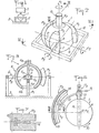
- the device 1 is constituted by an electromechanical converter with several degrees of freedom shown, in its embodiment according to FIG. 2, as capable of authorizing a displacement, an orientation or an adjustment according to three degrees of freedom corresponding to three axes of rotation. These axes or degrees of freedom are references A 1 , A 2 and A 3 , intersecting at a common point 0.
- the electro-mechanical converter 1 comprises a body 4 capable of being physically connected to the device 2 by any suitable means such as a radial extension 4a materializing, preferably, the axis A1.
- the body 4 is mounted on the support 3 by means 5 providing it with freedom of relative movement in rotation, at least partially, on three axes.
- the means 5 are constituted in the form of a universal joint centered on the center O while being disposed inside the body 4 constituted by a hollow body.
- the universal joint comprises a ball joint constituted by a spherical piece 5a secured to the body 4 by a radial rod 5b.
- the part 5a cooperates with a housing 5c, in two assemblable parts, provided at the end of an upright 5d rising from the support 3 and passing through the hollow body 4 through an opening 4b.
- the rod 5b and the upright 5d coincide with the axis A and thus confer a possibility of total and reversible rotation of the body 4 on this axis.
- the means 5 could be produced differently and, for example, the universal joint could be formed directly by an internal housing or body 4 made in two assemblable parts to allow the mounting and dismounting of a spherical part carried by the upright.
- the electromechanical converter also comprises electromagnetic means M or inductors intended to cooperate with the body 4. These means M are carried by a structure 6 rising from the support 2.
- the structure 6 can take any particular form corresponding to the selected application and is shown, in Figure 2, only by way of nonlimiting example in the form of a planar frame.
- the means M are each assigned a degree of freedom or an axis of rotation and for this reason bear the indices 1, 2 and 3 corresponding thereto.
- the electromagnetic means M to M 3 are preferably carried by the structure 6, so that their plane of symmetry corresponds with the diametrical plane P of the body 4, perpendicular to the axis A and passing through the point or center O.
- the connection can be established by suitable members 7 taking into account the possibilities of mounting and dismounting of the means M 1 to M 3 , as well as the specific obligations inherent in their electromagnetic operation.
- the means M are arranged outside of the body 4 which necessarily has a spherical outer surface centered on the center O.
- the electromagnetic means M is arranged so that its plane of influence corresponds to the diametral plane P while the means M 2 and M 3 are arranged in two perpendicular planes so that the plane of influence of each of them is perpendicular on plane P.
- the inductors M 1 to M 3 are each arranged so that their longitudinal plane of symmetry is the plane formed by the two axes other than that on which they act.
- the means M 1 to M 3 can be arranged in three distinct planes having in common only the center of the sphere.
- the electromagnetic means M to M 3 are intended to create radial magnetic fields with tangential displacement, so as to cause, each in its plane of influence, a rotation of the body 4 on the axis perpendicular to such a plane.
- the means M consist of laminated masses 8 (FIGS. 4 and 5) machined so as to delimit, on their surface opposite that of the spherical body 4, teeth 10 between which the windings are placed.
Landscapes
- Engineering & Computer Science (AREA)
- Robotics (AREA)
- Mechanical Engineering (AREA)
- Physics & Mathematics (AREA)
- Chemical & Material Sciences (AREA)
- Combustion & Propulsion (AREA)
- Electromagnetism (AREA)
- Power Engineering (AREA)
- Linear Motors (AREA)
- Manipulator (AREA)
Applications Claiming Priority (2)
| Application Number | Priority Date | Filing Date | Title |
|---|---|---|---|
| FR8220450 | 1982-12-07 | ||
| FR8220450A FR2537301B1 (fr) | 1982-12-07 | 1982-12-07 | Convertisseur electro-mecanique a plusieurs degres de liberte |
Publications (2)
| Publication Number | Publication Date |
|---|---|
| EP0113267A1 true EP0113267A1 (de) | 1984-07-11 |
| EP0113267B1 EP0113267B1 (de) | 1986-04-16 |
Family
ID=9279847
Family Applications (1)
| Application Number | Title | Priority Date | Filing Date |
|---|---|---|---|
| EP83402345A Expired EP0113267B1 (de) | 1982-12-07 | 1983-12-06 | Elektromechanischer Umformer mit mehreren Freiheitsgraden |
Country Status (4)
| Country | Link |
|---|---|
| US (1) | US4634889A (de) |
| EP (1) | EP0113267B1 (de) |
| DE (1) | DE3363098D1 (de) |
| FR (1) | FR2537301B1 (de) |
Cited By (10)
| Publication number | Priority date | Publication date | Assignee | Title |
|---|---|---|---|---|
| FR2606225A1 (fr) * | 1986-10-30 | 1988-05-06 | France Etat Armement | Actionneur electromagnetique a deux entrefers |
| WO1988005996A3 (en) * | 1987-02-17 | 1988-09-22 | Martin Marietta Corp | Triaxis stabilized platform |
| EP0231109A3 (en) * | 1986-01-24 | 1989-03-08 | Kabushiki Kaisha Toshiba | Non-contact positioning device |
| FR2658673A1 (fr) * | 1990-02-22 | 1991-08-23 | Sagem | Moteur electrique a courant continu a deux axes de rotation, notamment pour viseur. |
| US5413010A (en) * | 1991-07-31 | 1995-05-09 | Mitsubishi Jukogyo Kabushiki Kaisha | Electric motor having a spherical rotor and its application apparatus |
| WO1995007793A3 (en) * | 1993-09-13 | 1995-11-30 | United Technologies Corp | Force and position controlled manipulator |
| EP1529256B1 (de) * | 2002-08-06 | 2010-10-06 | Rockwell Collins, Inc. | Direkte antriebssteuereinheit mit haptischer rückmeldung |
| CN104882250A (zh) * | 2015-06-02 | 2015-09-02 | 梁少文 | 一种带报警器且便于拆卸维护的变压器 |
| US20180264574A1 (en) * | 2017-03-17 | 2018-09-20 | Faurecia Emissions Control Technologies, Germany Gmbh | Joining device and method for producing an exhaust gas system |
| WO2021243515A1 (zh) * | 2020-06-01 | 2021-12-09 | 大连理工大学 | 一种电磁驱动两自由度球型机器人手腕及其控制方法 |
Families Citing this family (19)
| Publication number | Priority date | Publication date | Assignee | Title |
|---|---|---|---|---|
| US4908558A (en) * | 1988-04-22 | 1990-03-13 | Contraves Goerz Corporation | Spherical motion simulator |
| US5447409A (en) * | 1989-10-20 | 1995-09-05 | Applied Materials, Inc. | Robot assembly |
| DE69032945T2 (de) * | 1989-10-20 | 1999-09-16 | Applied Materials, Inc. | Robotereinrichtung |
| US5280225A (en) * | 1992-04-20 | 1994-01-18 | Motorola, Inc. | Method and apparatus for multi-axis rotational motion |
| US5410232A (en) * | 1992-12-18 | 1995-04-25 | Georgia Tech Research Corporation | Spherical motor and method |
| US5402049A (en) * | 1992-12-18 | 1995-03-28 | Georgia Tech Research Corporation | System and method for controlling a variable reluctance spherical motor |
| US5376862A (en) * | 1993-01-28 | 1994-12-27 | Applied Materials, Inc. | Dual coaxial magnetic couplers for vacuum chamber robot assembly |
| US6664666B2 (en) * | 1998-12-23 | 2003-12-16 | Engineering Matters, Inc. | Motor assembly allowing output in multiple degrees of freedom |
| US6683581B2 (en) * | 2000-12-29 | 2004-01-27 | Bellsouth Intellectual Property Corporation | Antenna alignment devices |
| GB2388064B (en) * | 2002-05-01 | 2005-06-08 | Kfh Design Ltd | Precise positioning of an object |
| EP2271256B1 (de) * | 2008-03-27 | 2012-08-01 | Koninklijke Philips Electronics N.V. | Verfahren und system zur messung eines bestimmten objekts |
| CN101732870A (zh) * | 2008-11-07 | 2010-06-16 | 鸿富锦精密工业(深圳)有限公司 | 仿真眼睛 |
| US8498741B2 (en) * | 2009-09-22 | 2013-07-30 | Gm Global Technology Operations | Dexterous humanoid robotic wrist |
| NL2005011C2 (nl) | 2010-07-01 | 2012-01-03 | Be-Kking Man B V | Roterende machine voor compressie en decompressie. |
| US9287760B2 (en) | 2012-08-20 | 2016-03-15 | Remec Broadband Wireless Holdings, Inc. | Highly reliable actuator with multiple degrees of freedom and method for moving a payload using the actuator |
| TWI497876B (zh) * | 2013-01-31 | 2015-08-21 | Univ Chung Hua | Electromagnetic drive spheres and their vehicles |
| WO2016018254A1 (en) * | 2014-07-29 | 2016-02-04 | Hewlett-Packard Development Company, L.P. | Lockable connector device |
| CN112025760B (zh) * | 2020-09-01 | 2023-01-31 | 重庆邮电大学 | 一种电磁驱动机械关节 |
| US12552259B2 (en) | 2022-06-01 | 2026-02-17 | Caterpillar Global Mining Equipment LLC. | Electromechanical joint for conductor arm having multiple degrees of freedom |
Citations (10)
| Publication number | Priority date | Publication date | Assignee | Title |
|---|---|---|---|---|
| FR674513A (fr) * | 1928-05-12 | 1930-01-29 | Acec | Perfectionnements apportés aux procédés de démarrage et de synchronisation des commutatrices en cascade |
| CH312381A (de) * | 1952-06-05 | 1955-12-31 | Philips Nv | Umschaltbarer Wechselstrommotor. |
| DE977623C (de) * | 1962-09-09 | 1967-11-30 | Telefunken Patent | Momentengeber |
| FR2040907A5 (de) * | 1969-04-16 | 1971-01-22 | Vierne Andre | |
| FR2180551A1 (de) * | 1972-04-20 | 1973-11-30 | Calka Maurice | |
| FR2198299A1 (de) * | 1972-09-06 | 1974-03-29 | Denis Michel | |
| FR2325974A1 (fr) * | 1975-09-24 | 1977-04-22 | Marconi Co Ltd | Socle stabilise pour porter un dispositif sur un appareil de locomotion |
| FR2419341A1 (fr) * | 1978-03-11 | 1979-10-05 | Vyzk Vyvojovy Ustav Zavodu | Dispositif pour le transport des elements d'introduction de la trame en particulier dans les metiers a tisser a pas marchant |
| FR2452193A1 (fr) * | 1979-03-23 | 1980-10-17 | Gradient | Moteur electrique spherique |
| DE3122695A1 (de) * | 1981-06-06 | 1983-01-05 | Herbert Prof. Dr.-Ing. 3300 Braunschweig Weh | "asynchronmotoren mit grossen abstossenden normalkraeften" |
Family Cites Families (6)
| Publication number | Priority date | Publication date | Assignee | Title |
|---|---|---|---|---|
| US3398341A (en) * | 1965-02-16 | 1968-08-20 | Army Usa | Active compensation network to stabilize an inertial platform |
| US3441936A (en) * | 1965-03-29 | 1969-04-29 | Lear Siegler Inc | Spherically mounted floating radiation reflector |
| CA1034393A (en) * | 1976-10-13 | 1978-07-11 | Spar Aerospace Products Limited | Powered wrist joint |
| US4143212A (en) * | 1976-10-18 | 1979-03-06 | Tokyo Shibaura Electric Co., Ltd. | Sealed storage battery |
| SU657539A1 (ru) * | 1977-01-17 | 1979-04-15 | Московский Ордена Ленина Энергетический Институт | Двухкоординатный шаговый электродвигатель |
| US4437047A (en) * | 1981-07-13 | 1984-03-13 | Hughes Aircraft Company | System for autonomous earth-pointing acquisition of a dual-spin satellite |
-
1982
- 1982-12-07 FR FR8220450A patent/FR2537301B1/fr not_active Expired
-
1983
- 1983-12-06 DE DE8383402345T patent/DE3363098D1/de not_active Expired
- 1983-12-06 EP EP83402345A patent/EP0113267B1/de not_active Expired
- 1983-12-07 US US06/558,980 patent/US4634889A/en not_active Expired - Fee Related
Patent Citations (10)
| Publication number | Priority date | Publication date | Assignee | Title |
|---|---|---|---|---|
| FR674513A (fr) * | 1928-05-12 | 1930-01-29 | Acec | Perfectionnements apportés aux procédés de démarrage et de synchronisation des commutatrices en cascade |
| CH312381A (de) * | 1952-06-05 | 1955-12-31 | Philips Nv | Umschaltbarer Wechselstrommotor. |
| DE977623C (de) * | 1962-09-09 | 1967-11-30 | Telefunken Patent | Momentengeber |
| FR2040907A5 (de) * | 1969-04-16 | 1971-01-22 | Vierne Andre | |
| FR2180551A1 (de) * | 1972-04-20 | 1973-11-30 | Calka Maurice | |
| FR2198299A1 (de) * | 1972-09-06 | 1974-03-29 | Denis Michel | |
| FR2325974A1 (fr) * | 1975-09-24 | 1977-04-22 | Marconi Co Ltd | Socle stabilise pour porter un dispositif sur un appareil de locomotion |
| FR2419341A1 (fr) * | 1978-03-11 | 1979-10-05 | Vyzk Vyvojovy Ustav Zavodu | Dispositif pour le transport des elements d'introduction de la trame en particulier dans les metiers a tisser a pas marchant |
| FR2452193A1 (fr) * | 1979-03-23 | 1980-10-17 | Gradient | Moteur electrique spherique |
| DE3122695A1 (de) * | 1981-06-06 | 1983-01-05 | Herbert Prof. Dr.-Ing. 3300 Braunschweig Weh | "asynchronmotoren mit grossen abstossenden normalkraeften" |
Non-Patent Citations (1)
| Title |
|---|
| SOVIET INVENTIONS ILLUSTRATED, Derwent, semaine C01, 13.02.1980 * |
Cited By (13)
| Publication number | Priority date | Publication date | Assignee | Title |
|---|---|---|---|---|
| EP0231109A3 (en) * | 1986-01-24 | 1989-03-08 | Kabushiki Kaisha Toshiba | Non-contact positioning device |
| FR2606225A1 (fr) * | 1986-10-30 | 1988-05-06 | France Etat Armement | Actionneur electromagnetique a deux entrefers |
| WO1988005996A3 (en) * | 1987-02-17 | 1988-09-22 | Martin Marietta Corp | Triaxis stabilized platform |
| FR2658673A1 (fr) * | 1990-02-22 | 1991-08-23 | Sagem | Moteur electrique a courant continu a deux axes de rotation, notamment pour viseur. |
| EP0453328A3 (de) * | 1990-02-22 | 1991-10-30 | Societe D'applications Generales D'electricite Et De Mecanique Sagem | Zwei Drehungsachse aufweisendee elekrischer Gleichstrommotor, insbesondere für einen optischen Sucher |
| EP0526774B1 (de) * | 1991-07-31 | 1996-03-20 | Mitsubishi Jukogyo Kabushiki Kaisha | Elektrischer Motor mit einem sphärischen Läufer und seine Anwendungsvorrichtung |
| US5413010A (en) * | 1991-07-31 | 1995-05-09 | Mitsubishi Jukogyo Kabushiki Kaisha | Electric motor having a spherical rotor and its application apparatus |
| WO1995007793A3 (en) * | 1993-09-13 | 1995-11-30 | United Technologies Corp | Force and position controlled manipulator |
| EP1529256B1 (de) * | 2002-08-06 | 2010-10-06 | Rockwell Collins, Inc. | Direkte antriebssteuereinheit mit haptischer rückmeldung |
| CN104882250A (zh) * | 2015-06-02 | 2015-09-02 | 梁少文 | 一种带报警器且便于拆卸维护的变压器 |
| US20180264574A1 (en) * | 2017-03-17 | 2018-09-20 | Faurecia Emissions Control Technologies, Germany Gmbh | Joining device and method for producing an exhaust gas system |
| WO2021243515A1 (zh) * | 2020-06-01 | 2021-12-09 | 大连理工大学 | 一种电磁驱动两自由度球型机器人手腕及其控制方法 |
| US11446814B2 (en) | 2020-06-01 | 2022-09-20 | Dalian University Of Technology | Electromagnetic drive spherical robotic wrist with two degrees of freedom and control method therefor |
Also Published As
| Publication number | Publication date |
|---|---|
| DE3363098D1 (en) | 1986-05-22 |
| EP0113267B1 (de) | 1986-04-16 |
| US4634889A (en) | 1987-01-06 |
| FR2537301A1 (fr) | 1984-06-08 |
| FR2537301B1 (fr) | 1986-01-24 |
Similar Documents
| Publication | Publication Date | Title |
|---|---|---|
| EP0113267B1 (de) | Elektromechanischer Umformer mit mehreren Freiheitsgraden | |
| EP0616665B1 (de) | Magnetische lagervorrichtung und mechanischer anschlag zum positionieren einesdrehkörpers gegenüber einem stator | |
| EP0641061B1 (de) | Magnetische Lagervorrichtung für das Kippen eines Drehkörpers in Bezug auf einen Ständerkörper | |
| FR2677507A1 (fr) | Moteur pas-a-pas ou synchrone economique. | |
| EP2990375A2 (de) | Mikromechanische vorrichtung mit elektromagnetischer betätigung | |
| WO1986004534A1 (fr) | Procede et dispositif de deplacement du point d'impact d'un faisceau laser sur une piece | |
| FR2742497A1 (fr) | Palier magnetique a actionneurs et capteurs alternes | |
| FR2732734A1 (fr) | Palier magnetique miniature a au moins un axe actif | |
| EP2071708B1 (de) | Motorisierter Drehkranz | |
| CH642201A5 (fr) | Moteur electrique synchrone a tres faible inertie rotorique a mouvement conique equilibre. | |
| EP0401084B1 (de) | Vorrichtung mit mehreren Winkelpositionssensoren | |
| FR2492605A1 (fr) | Moteur electrique transformant les impulsions d'attraction magnetique du rotor par le stator en un mouvement de rotation du rotor | |
| EP0268619A1 (de) | Elektromagnetische antriebsvorrichtung. | |
| EP2741406A1 (de) | Schrittschaltmotor mit Doppelrotor | |
| EP0174966A1 (de) | Vorrichtung zur vielpoligen magnetisierung. | |
| CH493960A (fr) | Dispositif d'entraînement électromagnétique comprenant une armature à position d'équilibre réglable | |
| EP0790540B1 (de) | Elektromagnetischer Transdukter mit multipolaren Permanentmagneten | |
| FR2713292A1 (fr) | Dispositif à palier magnétique pour le basculement d'un corps tournant par rapport à un corps statorique. | |
| FR3032570A1 (fr) | Moteur electrique pivotant | |
| FR2894341A1 (fr) | Dispositif electromecanique comportant un element pouvant tourner autour d'au moins un premier et un deuxieme axe de rotation | |
| FR2696059A1 (fr) | Moteur-couple à induit plat et dispositif de commande en débattement angulaire le comportant. | |
| FR2497571A1 (fr) | Detecteur de position pour rotor de machine electrique | |
| FR2503952A1 (fr) | Moteur electrique monophase pas a pas | |
| FR2743217A1 (fr) | Accelarateur ou actionneur lineaire | |
| CH720941A2 (fr) | Génératrice électrique et dispositif portable comprenant une telle génératrice |
Legal Events
| Date | Code | Title | Description |
|---|---|---|---|
| PUAI | Public reference made under article 153(3) epc to a published international application that has entered the european phase |
Free format text: ORIGINAL CODE: 0009012 |
|
| AK | Designated contracting states |
Designated state(s): CH DE FR GB IT LI NL SE |
|
| 17P | Request for examination filed |
Effective date: 19840622 |
|
| GRAA | (expected) grant |
Free format text: ORIGINAL CODE: 0009210 |
|
| AK | Designated contracting states |
Kind code of ref document: B1 Designated state(s): CH DE FR GB IT LI NL SE |
|
| ITF | It: translation for a ep patent filed | ||
| REF | Corresponds to: |
Ref document number: 3363098 Country of ref document: DE Date of ref document: 19860522 |
|
| PLBE | No opposition filed within time limit |
Free format text: ORIGINAL CODE: 0009261 |
|
| STAA | Information on the status of an ep patent application or granted ep patent |
Free format text: STATUS: NO OPPOSITION FILED WITHIN TIME LIMIT |
|
| 26N | No opposition filed | ||
| ITTA | It: last paid annual fee | ||
| PGFP | Annual fee paid to national office [announced via postgrant information from national office to epo] |
Ref country code: NL Payment date: 19911231 Year of fee payment: 9 |
|
| PGFP | Annual fee paid to national office [announced via postgrant information from national office to epo] |
Ref country code: DE Payment date: 19920226 Year of fee payment: 9 |
|
| PGFP | Annual fee paid to national office [announced via postgrant information from national office to epo] |
Ref country code: CH Payment date: 19921119 Year of fee payment: 10 |
|
| PGFP | Annual fee paid to national office [announced via postgrant information from national office to epo] |
Ref country code: SE Payment date: 19921123 Year of fee payment: 10 |
|
| PGFP | Annual fee paid to national office [announced via postgrant information from national office to epo] |
Ref country code: GB Payment date: 19921124 Year of fee payment: 10 |
|
| PG25 | Lapsed in a contracting state [announced via postgrant information from national office to epo] |
Ref country code: NL Effective date: 19930701 |
|
| NLV4 | Nl: lapsed or anulled due to non-payment of the annual fee | ||
| PG25 | Lapsed in a contracting state [announced via postgrant information from national office to epo] |
Ref country code: DE Effective date: 19930901 |
|
| PGFP | Annual fee paid to national office [announced via postgrant information from national office to epo] |
Ref country code: FR Payment date: 19931007 Year of fee payment: 11 |
|
| PG25 | Lapsed in a contracting state [announced via postgrant information from national office to epo] |
Ref country code: GB Effective date: 19931206 |
|
| PG25 | Lapsed in a contracting state [announced via postgrant information from national office to epo] |
Ref country code: SE Effective date: 19931207 |
|
| PG25 | Lapsed in a contracting state [announced via postgrant information from national office to epo] |
Ref country code: LI Effective date: 19931231 Ref country code: CH Effective date: 19931231 |
|
| GBPC | Gb: european patent ceased through non-payment of renewal fee |
Effective date: 19931206 |
|
| REG | Reference to a national code |
Ref country code: CH Ref legal event code: PL |
|
| EUG | Se: european patent has lapsed |
Ref document number: 83402345.9 Effective date: 19940710 |
|
| PG25 | Lapsed in a contracting state [announced via postgrant information from national office to epo] |
Ref country code: FR Effective date: 19950831 |
|
| REG | Reference to a national code |
Ref country code: FR Ref legal event code: ST |