EP0115235A2 - Vorrichtung und Verfahren zum Stapeln und Beladen von Filzen - Google Patents
Vorrichtung und Verfahren zum Stapeln und Beladen von Filzen Download PDFInfo
- Publication number
- EP0115235A2 EP0115235A2 EP83402507A EP83402507A EP0115235A2 EP 0115235 A2 EP0115235 A2 EP 0115235A2 EP 83402507 A EP83402507 A EP 83402507A EP 83402507 A EP83402507 A EP 83402507A EP 0115235 A2 EP0115235 A2 EP 0115235A2
- Authority
- EP
- European Patent Office
- Prior art keywords
- felts
- chamber
- unit
- container
- floor
- Prior art date
- Legal status (The legal status is an assumption and is not a legal conclusion. Google has not performed a legal analysis and makes no representation as to the accuracy of the status listed.)
- Granted
Links
Images



Classifications
-
- B—PERFORMING OPERATIONS; TRANSPORTING
- B30—PRESSES
- B30B—PRESSES IN GENERAL
- B30B9/00—Presses specially adapted for particular purposes
- B30B9/30—Presses specially adapted for particular purposes for baling; Compression boxes therefor
-
- B—PERFORMING OPERATIONS; TRANSPORTING
- B65—CONVEYING; PACKING; STORING; HANDLING THIN OR FILAMENTARY MATERIAL
- B65B—MACHINES, APPARATUS OR DEVICES FOR, OR METHODS OF, PACKAGING ARTICLES OR MATERIALS; UNPACKING
- B65B63/00—Auxiliary devices, not otherwise provided for, for operating on articles or materials to be packaged
- B65B63/02—Auxiliary devices, not otherwise provided for, for operating on articles or materials to be packaged for compressing or compacting articles or materials prior to wrapping or insertion in containers or receptacles
Definitions
- the present invention relates to the loading and packaging of articles and, more particularly, of insulation felts or other materials of similar type which come from an output conveyor in a production line.
- the present invention makes it possible to remedy these two problems by automatically collecting and stacking the felts when they leave a production line, by transporting the collected felts to a compression chamber, then by compressing and placing them in a container.
- This improved device allows all these operations to be carried out while the production line is operating at full speed and without manual intervention by workers.
- This improved device can also be adjusted automatically so that if there is a change in the thickness of the insulation felts, the production line continues to operate at full speed.
- a device for handling insulation felts was the subject of US Patent No. 3,824,759. This device was a semi-automatic insulation felt handling machine which dealt with the problem of handling multiple felts by allowing the compression machine to treat two contiguous stacks at the same time.
- the device according to this invention included felt compression elements making it possible to successively compress these two contiguous stacks. It required at least one operator to collect the felts from the conveyor of the production line and deposit them in twin stacks intended for the compression elements.
- the present invention is an improvement on the inventions described above, which provides a plurality of conditioning chambers and a device for moving back and forth enabling the manipulation of as many stacks of insulation felts as the production chain into a product.
- the felt transfer device of the present invention receives a stack of felts preferably from an improved receiving tray or one or two-stage tray (also part of the present invention), and transfers the stack of the receiving and stacking area at one of the packaging chambers.
- the transfer device can move the felts away from this surface by pushing them, laterally, from either direction.
- the present invention employs elevating elements inside the conditioning chamber which lift a set of felts to a certain height and holding fingers which are then inserted below this set so as to allow the elements of elevation to descend to the floor of the room.
- the device for transferring the insulation felts begins the same cycle of operations in another conditioning chamber. Once the unit is compressed, and while the plate continues to hold the felts together, a piston moves from the rear of the chamber, crosses it and pushes the unit into a container, placed on standby on a chute.
- an object of the present invention is an automatic method and device for conditioning insulation felts, making it possible to form stacks of felts, to combine several stacks, to compress the combination to constitute a unit, and to move the combined unit to put it in a container.
- Another object of the present invention is an automatic method and device for packaging insulation felts in which there is reception of all the felts leaving the production line without there being any defective jamming or placement of a felt.
- Another object of the present invention is an automatic method and device for conditioning insulation felts which can be adjusted so as to handle felts of different thicknesses and of different dimensions.
- Another object of the present invention is an improved reception device on one or two stages intended to receive relatively light insulation felts coming from a conveyor and to collect them one above the other without initiating an unpleasant unevenness.
- Another object of the present invention is a method and a device in which a single transfer device can alternately supply several packaging chambers.
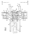
- the device of the present invention is placed directly below the conveyor 11 of a production line so as to receive insulation felts 10 moving in the direction of arrow A.
- a tray or two-stage receiving device 12 can be placed directly below the end of the conveyor 11 to receive the insulation felts 10, as shown by arrow B, and a photocell counter 9 records the passage of each felt .i0. The counting of the felts by the counter 9 is recorded and the results are used to actuate other parts of the device of the present invention as will be explained below.
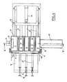
- the tray 12 has a pair of spaced sides 13a and 13b which extend downward from a point contiguous to the end of the conveyor 11 to a first pair of hatch doors 14a and 14b.
- the sides 13a and 13b are sufficiently spaced and have a length sufficient to allow one or more felts 10 to be collected on the doors 14a and 14b, as shown in FIG. 3.
- the felts 10 can have the same thickness and a predetermined length , or, alternatively, have a double thickness or a multiple thickness by folding and folding them to have a predetermined length.
- the first doors 14a and 14b can rotate around a pair of hinges 15a and 15b, respectively, to, first of all, maintain one or more felt 10s while being in the horizontal position then, when applying a predetermined signal, release the felts 10 by tilting down 90 degrees around the hinges 15a and 15b during an operating mode in the vertical direction.
- the felt (s) 10 then fall on doors 14c and 14d arranged lower in the horizontal direction and able to pivot, where two or more felts are gathered. Then, the second doors 14c and 14d rotate around hinges 15c and 15d up to the vertical, as represented by the dotted lines in FIG. 3, allowing the felts to fall vertically on a first surface 16, as indicated by the arrow B
- the two-stage receiving tray is particularly useful for firstly allowing the reception of a felt folded by the tray formed by the upper doors 14a and 14b, without it unfolding, then the fall onto the tray formed by doors 14c and 14d, where the felts are framed one on the other.
- a plurality of strips 12a of semi-flexible plastic material hang from the walls 13c and 13d of the plate and facilitate correct continuous framing of the felts during their fall onto the first surface 16.
- a felt transfer device 20 which will be described in detail later, moves horizontally from one side to the opposite side and , in doing so, proceeds to transfer the assembly or stack of felts from the first surface 16, then returns to its original position in a reciprocating movement.
- the surface 16 consists of a plate generally extending in the horizontal direction and resting on a fixed structure 17.
- the function of the felt transfer device 20 is to transfer to one and the other side of the first surface 16 of a set of felts 10.
- the felts 10 have entered one of a plurality conditioning chambers 30, as represented by arrow C (FIG. 3).
- the packaging chambers 30 are arranged on opposite lateral sides of the first surface 16.
- the transfer device 20 consists of vertical guides 21 extending between the top of the first surface 16 and the underside of this surface and connected to a source 23 of transfer energy.
- the source 23 can be one of the various types of displacement cylinders that are known in the art, for example, a hydraulic cylinder, a pneumatic cylinder, or an electrically controlled rod, and is supported by a structure 17.
- the vertical guides are move laterally in the slots 22 formed in the first surface 16. At the opposite lateral sides of the guides 21, at a predetermined point above the surface 16, are fixed to stops 24 coming into contact with the felts.
- the buffers 24 come into contact with all of the felts 10 on the first surface 16 after the stacking of a predetermined number of felts (as shown in FIG. 3 at 10).
- the transfer device 20 when activated by a felt counter or a felt weight control device, or the like (not shown), will move back and forth first to the right from its position shown in Figure 3 to transfer the stack of felts 10 in the direction of arrow C, then to the left to return to its original position shown in Figure 3, crossing the surface 16 while the guides 21 are move in the slots 22, which has the effect of transferring the stack into a given conditioning chamber 30.
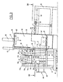
- FIG. 2 is an elevation view of a plurality of conditioning chambers 30 straddling the output conveyor 11 of the production line and immediately adjacent to the first surface 16.
- the chambers 30 are generally vertical structures (shown slightly inclined at Figure 2) to prevent an unstable stack of insulation felts from falling into the inlet opening 13 (shown in Figure 3) made of substantially rigid and solid material so as to withstand the various forces acting at this location.
- hinged doors of chambers 30a, 30b, 30c, and 30d are each pivotally mounted, for example in 30e, and are actuated by suitable jacks, such as jack 30f, so as to move between the positions.
- each room has a floor 31 for receiving the felts.
- the floor 31 In the floor 31 are spaced openings 36.
- Each chamber has an inner wall 32, an outer wall 33 parallel to the previous one, a front wall and a rear wall 34 and 35, also parallel to each other, all generally projecting vertically upwards on the floor 31.
- the floor 31 is at the same height above the manufacturing floor P as the first surface 16, and the chamber 30 has a ceiling 38, or other surface similar to a predetermined distance above the plane expensive 31, hence the formation of a complete room cover.
- the inner wall 32 descends downward from the ceiling 38 to a certain distance from the surface 16 so as to form a space 13 which is sufficient for the passage of a set of felts when the doors 30a, 30b, 30c, and 30d are open.
- each chamber 30 has a plurality of horizontal lifting elements 37 spaced from each other in a first position normally recessed inside the openings 36.
- the elements 37 will have a generally smooth surface so as to facilitate the movement of the felts.
- All the lifting elements 37 are joined, on the inner side, to a generally rectangular lifting frame 41, and the frame 41 can be raised to a second elevation position from the first withdrawal position by a source of energy 42, in the direction of the arrows D (FIGS. 3 and 5).
- the source 42 is securely fixed to the ceiling 38 by a strut 43 and its type is similar to that of the transfer energy source 23.
- each opening 36 of the floor is surrounded convex or curved edges 39.
- the edges 39 create a smooth surface in line with the lifting elements 37 so as to facilitate the movement of the felts.
- the front wall 34 has an opening 44 immediately adjacent to the floor 31 of the chamber, and on the outside of the wall 34 and extending from the opening 44 is a chute 45.
- a container K of the bag type (FIG. 6k), can be placed around the chute 45 to receive the compressed insulation felts.
- a piston 47 connected to a power source via the opening 46 sits immediately inside the wall 35 and moves just above the floor 31 of the chamber. The function of the piston 47 will be described later.
- the fingers 51 are elongated, flat blades, and are integral with a support frame 52, flat frame having the general shape of a C, and can move in a generally horizontal direction, represented by the arrow E (FIG. 3), through an opening 54 under the effect of an energy source 53
- Figure 4 shows that the fingers 51 will not be in contact with the elements 37 during this movement.
- the energy source 53 is of a type similar to that of the first two sources 23 and 42, cited above.
- the source 53 is fixed to the top of a stabilization frame 55 which is at a predetermined height above the floor 31.
- the frame 55 is at a preselected distance from the outer wall 33 so as to allow the fingers 51 to extend inside the chamber 30 and to be inserted below a set of felts which were then lifted by the elements 37 (because the elements 37 move from the position shown in solid lines to the position in phantom indicated in figure 5) or to withdraw from below the assembly so as to allow the elevation of successive assemblies or the compression of complete assemblies.
- the plate 62 extends horizontally and has approximately the same dimensions as an insulation felt; it is driven, as indicated by the arrow F, between a first normal height to a second lower height by means 66, as represented by the positions in solid line and in broken line in FIG. 5.
- the drive source 66 is of a type similar to that of the source 23 described previously.
- the second height (dotted line) is at a predetermined height immediately above the piston 47 and the floor 31 of the chamber, and the plate 62 compresses all the insulation felts 10 placed inside the chamber against the floor 31 to form a compact, tight unit when it reaches this position.
- the plate 62 comprises two movable rods 67 which extend in parallel through openings 68 made in the ceiling so as to guide the plate 62 in its upward and downward movements.
- an energy source 70 is connected to the piston 47 at a place contiguous to the rear wall 35.
- This source 70 is very similar to the sources described above, and is used to push the felts of compressed insulation to take them out of the chamber in the direction of the arrow G in FIG. 5 and pass them through the chute 45 before they enter the container K. This operation is also represented by the arrows G 'in figure 1.
- FIGS. 6a to 6s represent the individual steps of the present invention between the reception of the insulation felts at the outlet of the production line and their packaging in containers. A complete cycle will be described for a single chamber in operation, it being understood that there is a pair of felt packaging chambers 30 in operation at all times, as is clearly represented in FIG. 6s.
- the conveyor 11 inclined upwards from the production line, is arranged for conveying the felts to the upper plate of the two-stage plate 12 (or to the plate of a system with a floor, if applicable (not shown), if unfolded felts are being sent).
- the felts can be counted by passing at the height of the photocell counting cell 9 (FIG. 1).
- their size and weight can be determined by suitable means (not shown).
- the plate 12 will collect the felts 10 during their movement on the production line.
- a folded felt 10 is shown just before being delivered by the conveyor 10 to the upper plate of the two-stage receiving plate 12.
- the folded felt 10 is shown disposed on the hatch doors 14a and 14b, where it is momentarily held on these doors.
- the opening of the tray doors is controlled by computer so that the rest of the operations performs precisely.
- all other doors, movements, actuations of jacks and the like are also preferably controlled by computer so as to obtain precise and most efficient synchronization of the various operations.
- FIG. 6g it will be noted that three folded felts 10 are arranged on the surface 16, ready to be brought into contact with the stops of the felt transfer device 20.
- the device 20 is actuated by means of an appropriate signal, or preferably with computer control, and comes into contact with the felts 10, transferring them to the right , such as in FIG. 6h, inside the chamber 30.
- the transfer device 20 then automatically returns to its original position.
- the door jacks 30f (FIG. 1) have been actuated so as to close the stations 30b and 30d previously opened (not shown in the sequences of FIGS.
- the lifting jack 42 is actuated so as to lift the chassis and the elevation elements 37, which has the effect of raising the stack of three double or folded felts 10, as shown in FIG. 6i.
- the energy source 53 moves the retaining fingers 51 inwards, through the wall of the chamber, so that they come to engage below the stack of felts 10 in the chamber 30, while another stack of three felts 10 has been deposited on the surface 16, and the jack 42 has let the lifting elements 37 return to their low position.
- the chamber doors 30b, 30d open (not shown in the sequence in FIG.
- the felt transfer device 20, or shuttle moves the second set of three felts to introduce it into the chamber 30, below the first set of three markers therein, as can be seen in Figure 6k.
- the doors 30b and 30d then close, the operation of the jack 53 is reversed, which causes the withdrawal of the retaining fingers 51, causing the felts originally deposited in the chamber 30 to fall onto the pile of felts most recently put in place in the chamber 30, and the lifting jack 42 is again actuated to cause a new elevation by the elements 37 of the felts of the chamber 30, as can be seen in FIG. 61.
- this sequence continues until the insulation felts present in the chamber 30 become somewhat compressed, and the chamber 30 is substantially completely filled, as shown in FIG. 6n. It will obviously appear that after supply of the last group of felts 10 to the chamber 30, the lifting cylinder will not be actuated for the elevation of this last group. Then after a predetermined number of felts are in the chamber 30 and in response to an appropriate signal, the holding fingers 51 withdraw, leaving all of the sets of fire very constitute a large stack (see Figure 6 0 ). At this stage, another signal (not shown) is applied to the plate drive source 66, and the compression plate 62 is actuated in the direction of descent so as to compress all the insulation felts to make it a smaller unit.
- an end of cycle signal (not shown) is communicated to the energy source 70 and the piston 47 advances from its position contiguous to the rear wall 35 and pushes the compressed insulation felts to they pass through the opening 44 of the front wall and the chute 45 in order to be collected by a container K on standby, as can be seen in FIG. 6q.
- the felt transfer device 20, or shuttle has now assumed a rest position on the right side of the felt receiving surface 16, awaiting the deposition of felts on this surface, so that it will come in contact with the felts from its opposite side, to fill the chamber on the left, as shown in Figures 6o and 6p.
- the device 20, already in the rightmost position relative to the surface 16, may be caused to move to the left after that felts have been deposited on the surface 16, after which there is introduction of this group of felts into the opposite chamber 30 (not shown).
- the device 20 will work as a felt transfer device with each lateral movement, coming first into contact with the felts from one side, then from the other, like a real shuttle.
- a pair of chambers 30 could be filled in a substantially simultaneous manner.
Landscapes
- Engineering & Computer Science (AREA)
- Mechanical Engineering (AREA)
- Auxiliary Devices For And Details Of Packaging Control (AREA)
- Packages (AREA)
- Sheets, Magazines, And Separation Thereof (AREA)
- Basic Packing Technique (AREA)
- Nonwoven Fabrics (AREA)
- Dovetailed Work, And Nailing Machines And Stapling Machines For Wood (AREA)
- Sheet Holders (AREA)
- Portable Nailing Machines And Staplers (AREA)
- Electrical Discharge Machining, Electrochemical Machining, And Combined Machining (AREA)
- Stacking Of Articles And Auxiliary Devices (AREA)
Priority Applications (1)
| Application Number | Priority Date | Filing Date | Title |
|---|---|---|---|
| AT83402507T ATE34354T1 (de) | 1982-12-29 | 1983-12-22 | Vorrichtung und verfahren zum stapeln und beladen von filzen. |
Applications Claiming Priority (2)
| Application Number | Priority Date | Filing Date | Title |
|---|---|---|---|
| US454422 | 1982-12-29 | ||
| US06/454,422 US4501107A (en) | 1982-12-29 | 1982-12-29 | Batt stacker and loader and method therefor |
Publications (3)
| Publication Number | Publication Date |
|---|---|
| EP0115235A2 true EP0115235A2 (de) | 1984-08-08 |
| EP0115235A3 EP0115235A3 (en) | 1985-09-25 |
| EP0115235B1 EP0115235B1 (de) | 1988-05-18 |
Family
ID=23804541
Family Applications (1)
| Application Number | Title | Priority Date | Filing Date |
|---|---|---|---|
| EP83402507A Expired EP0115235B1 (de) | 1982-12-29 | 1983-12-22 | Vorrichtung und Verfahren zum Stapeln und Beladen von Filzen |
Country Status (7)
| Country | Link |
|---|---|
| US (1) | US4501107A (de) |
| EP (1) | EP0115235B1 (de) |
| JP (1) | JPS59134126A (de) |
| AT (1) | ATE34354T1 (de) |
| DE (1) | DE3376642D1 (de) |
| DK (1) | DK157072C (de) |
| FI (1) | FI834826A7 (de) |
Families Citing this family (24)
| Publication number | Priority date | Publication date | Assignee | Title |
|---|---|---|---|---|
| US4805383A (en) * | 1988-01-11 | 1989-02-21 | Manville Corporation | Batt packaging machine and method |
| GB8815330D0 (en) * | 1988-06-28 | 1988-08-03 | Procter & Gamble | Opening device for flexible bags filled with compressed flexible articles |
| US4934535A (en) * | 1989-04-04 | 1990-06-19 | The Procter & Gamble Company | Easy open flexible bag filled with compressed flexible articles and method and apparatus for making same |
| US5022216A (en) * | 1989-04-04 | 1991-06-11 | The Procter & Gamble Company | Method and apparatus for making easy open flexible bag filled with compressed flexible articles |
| US4966286A (en) * | 1989-06-26 | 1990-10-30 | The Procter & Gamble Company | Easy open flexible bag |
| US5054619A (en) * | 1989-12-15 | 1991-10-08 | The Procter & Gamble Company | Side opening flexible bag with longitudinally oriented carrying handle secured to side panels |
| US5065868A (en) * | 1990-10-23 | 1991-11-19 | Cornelissen Roger E | Package consisting of a paper bag compactly packing compressed flexible articles |
| US5050742A (en) * | 1990-11-02 | 1991-09-24 | The Procter & Gamble Company | Easy opening package containing compressed flexible articles |
| AU694823B2 (en) * | 1995-01-13 | 1998-07-30 | Fletcher Insulation Pty Ltd | An apparatus for packaging compressible articles |
| US5564261A (en) * | 1995-12-01 | 1996-10-15 | The Procter & Gamble Company | Method and apparatus for feeding resiliently compressed articles to a form/fill/seal machine |
| DE19703405C2 (de) * | 1997-01-30 | 1998-11-12 | Multipond Waegetechnik Gmbh | Mehrkomponentenfüllvorrichtung |
| US5822957A (en) * | 1997-08-07 | 1998-10-20 | Hay Bale, Inc | Equipment for sheathing hay bales in plastic |
| US6045324A (en) * | 1998-02-13 | 2000-04-04 | Redman; Paul W. | Stacking clamp |
| SE515445C2 (sv) * | 1999-02-22 | 2001-08-06 | Glenn Gustafsson | Förfarande och anordning för inpackning av mjuka element |
| US6931823B2 (en) * | 2003-08-27 | 2005-08-23 | Johns Manville International, Inc. | Packaging machine and method |
| US7243479B2 (en) * | 2005-06-23 | 2007-07-17 | Johns Manville | Apparatus and method for loading a packaging station of an insulation batt packager |
| US7409813B2 (en) * | 2005-12-28 | 2008-08-12 | Owens Corning Intellectual Capital Llc | High speed, high performance bagging assembly |
| EP1860033B1 (de) * | 2006-05-26 | 2011-01-12 | MTC - Macchine Trasformazione Carta Srl | Vorrichtung zur Umhüllung von Bögenstapeln |
| DE502007007131D1 (de) * | 2007-06-30 | 2011-06-16 | Trumpf Werkzeugmaschinen Gmbh | Werkzeugmaschine und Verfahren zum Verbringen eines Werkstückteils aus einer Auflageposition in eine Abfuhrposition |
| JP5389384B2 (ja) * | 2008-06-24 | 2014-01-15 | イチカワ株式会社 | 柔軟性が維持された抄紙用フェルト及びその梱包方法 |
| WO2012169374A1 (ja) * | 2011-06-08 | 2012-12-13 | 村田機械株式会社 | ワーク処理システム |
| CN102390550B (zh) * | 2011-07-06 | 2013-06-05 | 苏州维艾普新材料有限公司 | 一种真空绝热板高效多层的封装装置 |
| US10787303B2 (en) | 2016-05-29 | 2020-09-29 | Cellulose Material Solutions, LLC | Packaging insulation products and methods of making and using same |
| US11078007B2 (en) | 2016-06-27 | 2021-08-03 | Cellulose Material Solutions, LLC | Thermoplastic packaging insulation products and methods of making and using same |
Family Cites Families (21)
| Publication number | Priority date | Publication date | Assignee | Title |
|---|---|---|---|---|
| DE1020923B (de) * | 1957-12-12 | St. Regis Paper Company, New York, N. Y. (V. St. A.) | Verfahren und Vorrichtung zum Packen gefüllter Beutel in Umsäcke | |
| US1673014A (en) * | 1924-12-13 | 1928-06-12 | Western Electric Co | Apparatus for assembling articles |
| US2744369A (en) * | 1952-04-15 | 1956-05-08 | Seragnoli Ariosto | Stacking mechanism for wrapped articles |
| US2768489A (en) * | 1953-11-13 | 1956-10-30 | Gulf States Paper Corp | Process and apparatus for banding and packaging paper bags and the like |
| US2885097A (en) * | 1954-12-17 | 1959-05-05 | Barry Wehmiller Mach Co | Automatic pallet loader |
| US2869297A (en) * | 1955-01-31 | 1959-01-20 | Maryland Engineering Company | Method and apparatus for casing merchandise |
| US2869296A (en) * | 1956-07-31 | 1959-01-20 | Mary B Overman | Two-stage bagging machine |
| AT213338B (de) * | 1959-05-29 | 1961-02-10 | Sig Schweiz Industrieges | Maschine zum Stapeln von Beuteln u. dgl. zu Sammelpackungen |
| US3382643A (en) * | 1965-05-18 | 1968-05-14 | Owens Corning Fiberglass Corp | Method and apparatus for handling and packaging material |
| US3475877A (en) * | 1965-10-24 | 1969-11-04 | Herrick Waterman | Packing apparatus |
| US3442400A (en) * | 1967-03-02 | 1969-05-06 | Alvey Conveyor Mfg Co | Carton palletizing apparatus |
| GB1220922A (en) * | 1967-03-28 | 1971-01-27 | Graham Enock Mfg Co Ltd | Stacking apparatus |
| FR1573293A (de) * | 1968-05-20 | 1969-07-04 | ||
| US3486636A (en) * | 1969-01-14 | 1969-12-30 | Howard R Stroup | Bale stacker |
| US3585925A (en) * | 1969-05-28 | 1971-06-22 | Bemis Co Inc | Compression packing |
| US3818673A (en) * | 1972-11-21 | 1974-06-25 | Naremco Inc | Method and apparatus for packaging compressible materials |
| US3824759A (en) * | 1973-01-18 | 1974-07-23 | Owens Corning Fiberglass Corp | Method and apparatus for handling stackable bodies |
| US3908539A (en) * | 1974-09-13 | 1975-09-30 | Patco Packing Ltd | Apparatus for automatically stacking and compressing batts of compressible material |
| US3977155A (en) * | 1975-11-12 | 1976-08-31 | Certain-Teed Corporation | Batt stacker/loader |
| CA1037441A (en) * | 1977-04-19 | 1978-08-29 | Fiberglas Canada Ltd. | Apparatus for compressing and packaging articles |
| CA1055897A (en) * | 1977-06-23 | 1979-06-05 | Edward P. Banninga | Apparatus for compressing and packaging articles |
-
1982
- 1982-12-29 US US06/454,422 patent/US4501107A/en not_active Expired - Lifetime
-
1983
- 1983-12-21 DK DK589883A patent/DK157072C/da not_active IP Right Cessation
- 1983-12-22 EP EP83402507A patent/EP0115235B1/de not_active Expired
- 1983-12-22 DE DE8383402507T patent/DE3376642D1/de not_active Expired
- 1983-12-22 AT AT83402507T patent/ATE34354T1/de not_active IP Right Cessation
- 1983-12-28 FI FI834826A patent/FI834826A7/fi not_active Application Discontinuation
-
1984
- 1984-01-04 JP JP59000195A patent/JPS59134126A/ja active Pending
Also Published As
| Publication number | Publication date |
|---|---|
| FI834826L (fi) | 1984-06-30 |
| US4501107A (en) | 1985-02-26 |
| DK589883A (da) | 1984-06-30 |
| DK157072C (da) | 1990-04-30 |
| FI834826A0 (fi) | 1983-12-28 |
| ATE34354T1 (de) | 1988-06-15 |
| FI834826A7 (fi) | 1984-06-30 |
| EP0115235B1 (de) | 1988-05-18 |
| EP0115235A3 (en) | 1985-09-25 |
| JPS59134126A (ja) | 1984-08-01 |
| DK157072B (da) | 1989-11-06 |
| DK589883D0 (da) | 1983-12-21 |
| DE3376642D1 (en) | 1988-06-23 |
Similar Documents
| Publication | Publication Date | Title |
|---|---|---|
| EP0115235B1 (de) | Vorrichtung und Verfahren zum Stapeln und Beladen von Filzen | |
| CN113830375B (zh) | 一种全自动小包入盒机 | |
| KR20180107445A (ko) | 야채 수납 박스 운반장치 | |
| FR2543513A1 (fr) | Machine a palettiser pour recipients | |
| US4537008A (en) | Method and apparatus for packing soft packages into boxes | |
| EP3263469B1 (de) | Maschine zum extrahieren, auffalten, füllen und schliessen einer faltschachtel | |
| JP4119026B2 (ja) | 敷板回収装置 | |
| EP0679579B1 (de) | Vorrichtung zum Komprimieren und Verpacken eines Stapels von komprimierbaren Gegenständen | |
| FR2591996A1 (fr) | Machine pour mettre en boite des articles en groupes et plus particulierement des batons de sucreries | |
| EP2794132B1 (de) | Automasische be- und entladevorrichtung für flache aufrecht gestapelte flache objekte, sortiermaschine für flache objekte, verfahren zum automatischen entladen und postsortierverfahren | |
| FR2676941A1 (fr) | Module de case pour machine de tri. | |
| CA2220635C (en) | Apparatus for filling a bag with an article loaded in a tray | |
| JP2000153816A (ja) | 箱体の折り畳み処理方法及び装置 | |
| FR2472529A1 (fr) | Dispositif depileur de sacs vides, notamment pour une machine de remplissage | |
| FR2549020A1 (fr) | Installation de transport pour objets plats transportes par un flux d'air | |
| FR2623472A1 (fr) | Chaine de palettisation automatique d'emballages en piles | |
| FR2552743A1 (fr) | Machine d'empilage | |
| EP0151364A2 (de) | Verpackungsstrasse für Produkte mit einem Film in einem aus einem flachen vorgeschnittenen Zuschnitt hergestellten Behälter | |
| FR2654066A1 (fr) | Appareil pour positionner des alveoles receptrices de fruits et legumes dans des caisses en carton selon le principe de fermeture des caisses dites "caisses americaines" et le procede de positionnement des alveoles dans les caisses. | |
| FR2464190A1 (fr) | Dispositif d'obturation de recipients au moyen d'un couvercle en un materiau en feuille plastiquement deformable | |
| EP0204606B1 (de) | Vorrichtung zum Aufrichten, Füllen und Palettisieren von Behältern | |
| EP0045673B1 (de) | Automatische Verpackungsmaschine | |
| EP4119337B1 (de) | Müllpresse für kartons und anderes trockenes papier | |
| JPH0455923B2 (de) | ||
| JPH10273106A (ja) | 包装装置 |
Legal Events
| Date | Code | Title | Description |
|---|---|---|---|
| PUAI | Public reference made under article 153(3) epc to a published international application that has entered the european phase |
Free format text: ORIGINAL CODE: 0009012 |
|
| AK | Designated contracting states |
Designated state(s): AT BE CH DE FR GB IT LI LU NL SE |
|
| 17P | Request for examination filed |
Effective date: 19840817 |
|
| PUAL | Search report despatched |
Free format text: ORIGINAL CODE: 0009013 |
|
| AK | Designated contracting states |
Designated state(s): AT BE CH DE FR GB IT LI LU NL SE |
|
| 17Q | First examination report despatched |
Effective date: 19860714 |
|
| GRAA | (expected) grant |
Free format text: ORIGINAL CODE: 0009210 |
|
| AK | Designated contracting states |
Kind code of ref document: B1 Designated state(s): AT BE CH DE FR GB IT LI LU NL SE |
|
| PG25 | Lapsed in a contracting state [announced via postgrant information from national office to epo] |
Ref country code: AT Effective date: 19880518 |
|
| REF | Corresponds to: |
Ref document number: 34354 Country of ref document: AT Date of ref document: 19880615 Kind code of ref document: T |
|
| REF | Corresponds to: |
Ref document number: 3376642 Country of ref document: DE Date of ref document: 19880623 |
|
| ITF | It: translation for a ep patent filed | ||
| GBT | Gb: translation of ep patent filed (gb section 77(6)(a)/1977) | ||
| PLBE | No opposition filed within time limit |
Free format text: ORIGINAL CODE: 0009261 |
|
| STAA | Information on the status of an ep patent application or granted ep patent |
Free format text: STATUS: NO OPPOSITION FILED WITHIN TIME LIMIT |
|
| 26N | No opposition filed | ||
| PGFP | Annual fee paid to national office [announced via postgrant information from national office to epo] |
Ref country code: BE Payment date: 19910918 Year of fee payment: 9 |
|
| PGFP | Annual fee paid to national office [announced via postgrant information from national office to epo] |
Ref country code: LU Payment date: 19910920 Year of fee payment: 9 |
|
| PGFP | Annual fee paid to national office [announced via postgrant information from national office to epo] |
Ref country code: GB Payment date: 19910924 Year of fee payment: 9 |
|
| PGFP | Annual fee paid to national office [announced via postgrant information from national office to epo] |
Ref country code: SE Payment date: 19911011 Year of fee payment: 9 |
|
| PGFP | Annual fee paid to national office [announced via postgrant information from national office to epo] |
Ref country code: FR Payment date: 19911025 Year of fee payment: 9 |
|
| PGFP | Annual fee paid to national office [announced via postgrant information from national office to epo] |
Ref country code: DE Payment date: 19911108 Year of fee payment: 9 |
|
| PGFP | Annual fee paid to national office [announced via postgrant information from national office to epo] |
Ref country code: CH Payment date: 19911220 Year of fee payment: 9 |
|
| ITTA | It: last paid annual fee | ||
| EPTA | Lu: last paid annual fee | ||
| PG25 | Lapsed in a contracting state [announced via postgrant information from national office to epo] |
Ref country code: LU Free format text: LAPSE BECAUSE OF NON-PAYMENT OF DUE FEES Effective date: 19921222 Ref country code: GB Effective date: 19921222 |
|
| PG25 | Lapsed in a contracting state [announced via postgrant information from national office to epo] |
Ref country code: SE Effective date: 19921223 |
|
| PG25 | Lapsed in a contracting state [announced via postgrant information from national office to epo] |
Ref country code: LI Effective date: 19921231 Ref country code: CH Effective date: 19921231 Ref country code: BE Effective date: 19921231 |
|
| PGFP | Annual fee paid to national office [announced via postgrant information from national office to epo] |
Ref country code: NL Payment date: 19921231 Year of fee payment: 10 |
|
| BERE | Be: lapsed |
Owner name: CERTAINTEED CORP. Effective date: 19921231 |
|
| GBPC | Gb: european patent ceased through non-payment of renewal fee |
Effective date: 19921222 |
|
| PG25 | Lapsed in a contracting state [announced via postgrant information from national office to epo] |
Ref country code: FR Effective date: 19930831 |
|
| REG | Reference to a national code |
Ref country code: CH Ref legal event code: PL |
|
| PG25 | Lapsed in a contracting state [announced via postgrant information from national office to epo] |
Ref country code: DE Effective date: 19930901 |
|
| REG | Reference to a national code |
Ref country code: FR Ref legal event code: ST |
|
| PG25 | Lapsed in a contracting state [announced via postgrant information from national office to epo] |
Ref country code: NL Effective date: 19940701 |
|
| NLV4 | Nl: lapsed or anulled due to non-payment of the annual fee | ||
| EUG | Se: european patent has lapsed |
Ref document number: 83402507.4 Effective date: 19930709 |