EP0116010A2 - Agencement pour protéger contre l'étincelage un organe capillaire servant au soudage des fils dans un élément semi-conducteur - Google Patents
Agencement pour protéger contre l'étincelage un organe capillaire servant au soudage des fils dans un élément semi-conducteur Download PDFInfo
- Publication number
- EP0116010A2 EP0116010A2 EP84810001A EP84810001A EP0116010A2 EP 0116010 A2 EP0116010 A2 EP 0116010A2 EP 84810001 A EP84810001 A EP 84810001A EP 84810001 A EP84810001 A EP 84810001A EP 0116010 A2 EP0116010 A2 EP 0116010A2
- Authority
- EP
- European Patent Office
- Prior art keywords
- layer
- arrangement according
- capillary
- arrangement
- wire
- Prior art date
- Legal status (The legal status is an assumption and is not a legal conclusion. Google has not performed a legal analysis and makes no representation as to the accuracy of the status listed.)
- Granted
Links
Images

Classifications
-
- B—PERFORMING OPERATIONS; TRANSPORTING
- B23—MACHINE TOOLS; METAL-WORKING NOT OTHERWISE PROVIDED FOR
- B23K—SOLDERING OR UNSOLDERING; WELDING; CLADDING OR PLATING BY SOLDERING OR WELDING; CUTTING BY APPLYING HEAT LOCALLY, e.g. FLAME CUTTING; WORKING BY LASER BEAM
- B23K20/00—Non-electric welding by applying impact or other pressure, with or without the application of heat, e.g. cladding or plating
- B23K20/002—Non-electric welding by applying impact or other pressure, with or without the application of heat, e.g. cladding or plating specially adapted for particular articles or work
- B23K20/004—Wire welding
- B23K20/005—Capillary welding
- B23K20/007—Ball bonding
-
- H—ELECTRICITY
- H10—SEMICONDUCTOR DEVICES; ELECTRIC SOLID-STATE DEVICES NOT OTHERWISE PROVIDED FOR
- H10W—GENERIC PACKAGES, INTERCONNECTIONS, CONNECTORS OR OTHER CONSTRUCTIONAL DETAILS OF DEVICES COVERED BY CLASS H10
- H10W72/00—Interconnections or connectors in packages
- H10W72/01—Manufacture or treatment
- H10W72/015—Manufacture or treatment of bond wires
- H10W72/01551—Changing the shapes of bond wires
-
- H—ELECTRICITY
- H10—SEMICONDUCTOR DEVICES; ELECTRIC SOLID-STATE DEVICES NOT OTHERWISE PROVIDED FOR
- H10W—GENERIC PACKAGES, INTERCONNECTIONS, CONNECTORS OR OTHER CONSTRUCTIONAL DETAILS OF DEVICES COVERED BY CLASS H10
- H10W72/00—Interconnections or connectors in packages
- H10W72/071—Connecting or disconnecting
- H10W72/0711—Apparatus therefor
- H10W72/07141—Means for applying energy, e.g. ovens or lasers
-
- H—ELECTRICITY
- H10—SEMICONDUCTOR DEVICES; ELECTRIC SOLID-STATE DEVICES NOT OTHERWISE PROVIDED FOR
- H10W—GENERIC PACKAGES, INTERCONNECTIONS, CONNECTORS OR OTHER CONSTRUCTIONAL DETAILS OF DEVICES COVERED BY CLASS H10
- H10W72/00—Interconnections or connectors in packages
- H10W72/071—Connecting or disconnecting
- H10W72/075—Connecting or disconnecting of bond wires
- H10W72/07511—Treating the bonding area before connecting, e.g. by applying flux or cleaning
-
- H—ELECTRICITY
- H10—SEMICONDUCTOR DEVICES; ELECTRIC SOLID-STATE DEVICES NOT OTHERWISE PROVIDED FOR
- H10W—GENERIC PACKAGES, INTERCONNECTIONS, CONNECTORS OR OTHER CONSTRUCTIONAL DETAILS OF DEVICES COVERED BY CLASS H10
- H10W72/00—Interconnections or connectors in packages
- H10W72/071—Connecting or disconnecting
- H10W72/075—Connecting or disconnecting of bond wires
- H10W72/07531—Techniques
- H10W72/07532—Compression bonding, e.g. thermocompression bonding
- H10W72/07533—Ultrasonic bonding, e.g. thermosonic bonding
-
- H—ELECTRICITY
- H10—SEMICONDUCTOR DEVICES; ELECTRIC SOLID-STATE DEVICES NOT OTHERWISE PROVIDED FOR
- H10W—GENERIC PACKAGES, INTERCONNECTIONS, CONNECTORS OR OTHER CONSTRUCTIONAL DETAILS OF DEVICES COVERED BY CLASS H10
- H10W72/00—Interconnections or connectors in packages
- H10W72/50—Bond wires
- H10W72/551—Materials of bond wires
- H10W72/552—Materials of bond wires comprising metals or metalloids, e.g. silver
- H10W72/5522—Materials of bond wires comprising metals or metalloids, e.g. silver comprising gold [Au]
-
- H—ELECTRICITY
- H10—SEMICONDUCTOR DEVICES; ELECTRIC SOLID-STATE DEVICES NOT OTHERWISE PROVIDED FOR
- H10W—GENERIC PACKAGES, INTERCONNECTIONS, CONNECTORS OR OTHER CONSTRUCTIONAL DETAILS OF DEVICES COVERED BY CLASS H10
- H10W72/00—Interconnections or connectors in packages
- H10W72/50—Bond wires
- H10W72/551—Materials of bond wires
- H10W72/552—Materials of bond wires comprising metals or metalloids, e.g. silver
- H10W72/5524—Materials of bond wires comprising metals or metalloids, e.g. silver comprising aluminium [Al]
-
- H—ELECTRICITY
- H10—SEMICONDUCTOR DEVICES; ELECTRIC SOLID-STATE DEVICES NOT OTHERWISE PROVIDED FOR
- H10W—GENERIC PACKAGES, INTERCONNECTIONS, CONNECTORS OR OTHER CONSTRUCTIONAL DETAILS OF DEVICES COVERED BY CLASS H10
- H10W72/00—Interconnections or connectors in packages
- H10W72/50—Bond wires
- H10W72/551—Materials of bond wires
- H10W72/552—Materials of bond wires comprising metals or metalloids, e.g. silver
- H10W72/5525—Materials of bond wires comprising metals or metalloids, e.g. silver comprising copper [Cu]
Definitions
- the present invention relates to the capillary organs used for welding the wires which connect the contact pads of a chip to the poles of its envelope or support, and it relates to the protection of these organs against sparking and carbon deposits resulting from the electric arc.
- connection wires are generally made of gold or aluminum.
- thermocompression of a smooth gold ball and solder point (2) thermosonic fixation of a smooth gold ball and solder point and (3) fixation thermosonic or ultrasonic of a smooth aluminum ball and solder point.
- the wire after being welded to the contact pad of the chip and to the output terminal of its envelope, is broken in line with the last weld, then a ball is formed at its end for the next connection.
- the ball is formed by means of a charcoal electric arc, as described below.
- the weaker hydrogen arc was used. With the latter, the main cause of wear of the capillary organs was due to abrasion. The lifetime of such a body, made of ceramic, was commonly one million welds. By switching to a charcoal arc, however, this lifespan fell below half a million solders. The main reason for this fall, however, was no longer abrasion, but, on the one hand, sparking, which damages the end of the capillary organ, and, on the other hand, carbon deposits, which form inside the duct of this organ.
- the present invention tends to reduce sparking damage and carbon deposits during the formation of the balls using the carbon arc. It achieves this by coating the opening of the capillary member and at least part of its outer surface with a layer of an electrically conductive material and by connecting this layer to a reference potential. This has the effect of rapidly eliminating the arc discharge current from the capillary organ, avoiding damage due to sparking and the formation of carbon deposits.
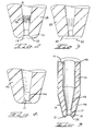
- Fig. 1 is a section of a capillary member, which illustrates the formation of a ball using a discharge generator or an electric arc.
- Fig. 2 is a section on a larger scale of the end of a capillary, similar to that of FIG. 1, which shows the erosion due to sparking.
- Fig. 3 is a section similar to that of FIG. 2, which shows how far sparking can wear out the end of a ca unprotected pillar.
- Fig. 4 is a section similar to that of FIGS. 2 and 3, which illustrates how the arc burns inside a capillary member made of an electrically conductive material.
- Fig. 5 is a section on a smaller scale of a capillary member, which constitutes the said embodiment.
- Fig. 1 represents a capillary member 23, of known type, which is made of fine-grained alumina ceramic, containing approximately 99.8% of A1 2 0 3 , of beryllium oxide, of glass, of quartz, of ruby or sapphire polycrystalline, in precious stone of the corundum group, such as ruby or sapphire or in other known materials.
- the member 23 is fixed to a heating support or to an ultrasonic transducer 24 of a welding machine.
- a wire 25, preferably made of gold, passes through the central duct of the member 23, which has a frustoconical part 15 and a capillary hole 17.
- This wire could also be made of another metal, such as aluminum, an aluminum alloy, palladium, copper, a copper alloy.
- the wire 25 and the support or transducer 24 are earthed 28 by conductors 1, 2, 3.
- a terminal of the generator 26 is earthed 28 by the conductor 3, while its other terminal is connected to a mobile electrode 27. At rest, the latter is separated from the member 23. When it comes to forming a ball 31, the electrode 27 is brought below the member 23, then brought closer to the latter, but without touching the end 29 of the wire 25, which leaves the member 23. When this electrode has reached the desired position, the generator 26 is activated so as to produce a discharge 30 against the end 29 of the wire 25.
- the welding face 22 at the end of the member 23 enters normally in contact with the wire 25 and the metal of the envelope output terminals, possibly also with the metallized chip of the chip during welding, a thin metal film 32 is formed on the face 22.
- the wire 25 is fed through the member 23, it rubs against the frustoconical part 15 of its conduit, which has the effect of producing a thin film 33 of the metal of the wire on this surface 15 of the member 23.
- the metallic films 32 and 33 offer a path of least resistance to the electric current of the discharge. When the latter occurs, the wire 25 and the ball 31 are strongly electrically charged.
- a spark or an electric arc 35 then occurs from the ball 31 and / or the wire 25 towards the film 32, as well as at 37, towards the film 33.
- a spark or an electric arc 36 can also occur directly between the electrode 27 and the film 32.
- the latter is heated and destroyed.
- the non-conductive material of the member 23 under this film is also destroyed by each spark, so that this results in a progressive erosion of the chamfer 18.
- the nature of this erosion is similar to that which is produced in machines. with EDM.
- Fig. 2 shows the damage 39 caused by sparking on the face 22 of a member 23 similar to that of FIG. 1 and made of non-conductive material.
- the main erosion normally occurs in the region of the chamfer 18 and in a part of the face 22, shown in broken lines.
- the chamfer 18 is hollowed out by erosion along the curvature of the ball 31, as is apparent from the eroded area 39.
- the spark or electric arc 37 (Fig. 1), which occurs where the wire 25 has rubbed against the surface 15, is less intense than that occurring against the face 22.
- the film 33 is much less important than that which forms on the face 22.
- the surface 15 is also more distant from the electrode 27 than the face 22.
- the spark 37 does not erode much the surface 15. However, it produces a burn and consequently a carbon deposit which tends to reduce the diameter of the conduit of the member 23 and ends up hampering the supply of the wire 25 through this conduit.
- this face becomes a good conductor. Direct sparking of the electrode 27 on this face becomes more important. The erosion then extends to all of this face 22 (shown in broken lines in FIG. 3), which flattens as shown at 42 in this figure.
- a capillary member made of an electrically conductive material such as tungsten carbide or titanium, such as member 43 of FIG. 4 erosion by sparking of this member occurs mainly in the hole 17, as shown in 44.
- the electric current seeks the path of least resistance and finds it in this case between the wire 25 and the walls of the hole 17 shown in broken lines in this figure.
- the resulting erosion therefore produces a widening of the outlet duct 17 of the member 23, which compromises the precision of the positioning of the welding points of the wire 25.
- Fig. 5 is a diametrical section of a capillary member according to the present invention. It has a body 45 which can be made of one or other of the materials mentioned above. Preferably, however, it will be made of a non-conductive material. This body is coated or plated with a conductive layer 46. In the case of a body 45 made of conductive material, a layer 46 will be chosen whose conductivity is significantly higher than that of the body 45. In general, the thickness of layer 46 does not need to exceed 0.0025 mm. This layer 46 must in particular be thin enough to adhere properly to the body 45, but still thick enough to constitute a good electrical conductor.
- the part of the layer 46 on the outer surface of the body 45 constitutes a path of low resistance to discharges from the electrode 27 through the part 16 of the layer 46, which covers the frustoconical part of the body 45 and which adjoins the face 22.
- the current of these discharges is thus conducted without damage to the ground 28 (Fig. 1).
- the capillary organ of FIG. 5 is intended to replace purely and simply that of FIG. 1.
- the path of the current coming from the electrode 27 is therefore composed of the layer 46 and of the support or of the ultrasonic transducer 24.
- the layer 46 consequently attracts the electric discharges far from the face 22 and protects the latter from the erosion.
- the layer 46 formed inside the body 45 has the same effect on the sparking shown at 37 in FIG. 1.
- the return to earth of this current from the wire 25 occurs through the part of the layer 46 lining the walls of the capillary duct of the member 45, 46, the part of this layer which covers the face 14 of the body. 45, its part on the external surface of the body 45 and finally the support or the ultrasonic transducer 24 of the welding machine.
- the carbon deposits on the walls of the capillary organ duct are thus practically eliminated.
- the layer 46 is applied to all the surfaces of the body 45. However, it would not need to line the walls of the hole 17 nor the welding face 22, comprising the chamfer 18 and the end 20 of the member. capillary, nor the external rounded part 21. As it would be difficult to spare these surfaces during the formation of the layer 46, it is deposited everywhere. Following the first uses of this member, the electrical discharges will have eliminated the coating of the walls of the hole 17 and of the face 22 and exposed the body 45. The layer 46 covering the frusto-conical part 16 which adjoins the face 22 will then act as a lightning rod and will attract electrical discharges away from the face 22.
- a preferred embodiment of the capillary member according to the invention consists of a body made of fine-grained alumina ceramic, containing 99.8% Al 2 O 3 and a conductive layer of titanium nitride applied to this body.
Landscapes
- Engineering & Computer Science (AREA)
- Mechanical Engineering (AREA)
- Wire Bonding (AREA)
- Details Of Resistors (AREA)
- Emergency Protection Circuit Devices (AREA)
Abstract
Description
- La présente invention concerne les organes capillaires servant au soudage des fils qui relient les pastilles de contact d'une puce aux pôles de son enveloppe ou support, et elle a trait à la protection de ces organes contre l'étincelage et les dépôts charbonneux résultant de l'arc électrique.
- Dans la fabrication des éléments semiconducteurs, il est d'usage courant de loger les puces dans des enveloppes. Les connexions électriques entre une puce et son enveloppe sont réalisées par des fils soudés aux pastilles de contact de la puce et aux bornes de sortie de son enve- loppe. Selon le type d'élément semiconducteur, ces connexions sont faites à l'aide de fils très fins, dont le diamètre, dans les éléments semiconducteurs courants, est de l'ordre de 25 microns. Ce diamètre peut toutfois aller jusqu'à 500 microns dans les éléments de grande puissance. Ces fils de connexion sont généralement en or ou en aluminium. Plusieurs techniques sont connues pour souder un tel fil à une pastille de contact de la puce et à une borne de sortie de son enveloppe. On se limitera ici aux trois types spécifiques de soudage: (1) thermocompression d'une boule d'or lisse et point de soudure, (2) fixation thermosonique d'une boule d'or lisse et point de soudure et (3) fixation thermosonique ou par ultrasons d'une boule d'aluminium lisse et point de soudure. Ces trois techniques bien connues sont décrites dans "Precision 79 Semiconductor Bond- ing Handbook", édité par "Small Precision Tools, Inc., San Rafael, Cali- fornie, USA.
- . Lors du soudage selon les techniques susmentionnées, le fil, après avoir été soudé à la pastille de contact de la puce et à la borne de sortie de son enveloppe, est cassé au droit de la dernière soudure, puis une boule est formée à son extrémité en vue d'effectuer la connexion suivante.
- Actuellement, la boule est formée au moyen d'un arc électrique au charbon, comme décrit ci-après. Auparavant, on utilisait l'arc d'hydrogène, plus faible. Avec ce dernier, la principale cause d'usure des organes capillaires était due à l'abrasion. La durée de vie d'un tel organe, fait en céramique, était communément de un million de soudures. En passant à l'arc au charbon, cette durée de vie est toutefois tombée au-dessous d'un demi-million de soudures. La principale raison de cette chute n'a cependant plus été l'abrasion, mais, d'une part, l'étincelage, qui endommage l'extrémité de l'organe capillaire, et, d'autre part, les dépôts charbonneux, qui se forment à l'intérieur du conduit de cet organe.
- La présente invention tend à réduire les dommages dus à l'étincelage et les dépôts charbonneux pendant la formation des boules à l'aide de l'arc au charbon. Elle y parvient en revêtant l'ouverture de l'organe capillaire et au moins une partie de sa surface extérieure d'une couche en un matériau conducteur électriquement et en branchant cette couche à un potentiel de référence. Cela a pour effet d'éliminer rapidement de l'organe capillaire le courant de décharge de l'arc, en évitant les dommages dus à l'étincelage ainsi que la formation de dépôts charbonneux.
- Une forme d'exécution de l'arrangement selon l'invention est représentée schématiquement et à simple titre d'exemple au dessin.
- La Fig. 1 est une coupe d'un organe capillaire, qui illustre la formation d'une boule à l'aide d'un générateur de décharge ou d'un arc électrique.
- La Fig. 2 est une coupe à plus grande échelle de l'extrémité d'un capillaire, semblable à celui de la Fig. 1, qui fait voir l'érosion due à l'étincelage.
- La Fig. 3 est une coupe semblable à celle de la Fig. 2, qui montre jusqu'à quel point l'étincelage peut user l'extrémité d'un organe capillaire non protégé.
- La Fig. 4 est une coupe semblable à celle des Fig. 2 et 3, qui illustre comment l'arc brûle l'intérieur d'un organe capillaire fait en un matériau conducteur électriquement.
- La Fig. 5 est une coupe à plus petite échelle d'un organe capillaire, qui constitue la dite forme d'exécution.
- La Fig. 1 représente un organe capillaire 23, de type connu, qui est fait en céramique d'alumine à grain fin, contenant environ 99,8% de A1203, en oxyde de béryllium, en verre, en quartz, en rubis ou saphir polycristallin, en pierre précieuse du groupe corindon, tel que rubis ou saphir ou en d'autres matériaux connus. L'organe 23 est fixé à un support chauffant ou à un transducteur ultrasonique 24 d'une machine à souder. Un fil 25, de préférence en or, passe à travers le conduit central de l'organe 23, qui présente une partie tronconique 15 et un trou capillaire 17. Ce fil pourrait aussi être fait en un autre métal, tel que l'aluminium, un alliage d'aluminium, le palladium, le cuivre, un alliage de cuivre.
- Le fil 25 et le support ou transducteur 24 sont mis à la terre 28 par des conducteurs 1, 2, 3. Un générateur électrique 26 à arc, généralement du type à décharge capacitive, produit des décharges de courant continu à des tensions allant de 700 à 2000 volts. Une borne du générateur 26 est mise à la terre 28 par le conducteur 3, tandis que son autre borne est connectée à une électrode mobile 27. Au repos, cette dernière est écartée de l'organe 23. Lorsqu'il s'agit de former une boule 31, l'électrode 27 est amenée au-dessous de l'organe 23, puis rapprochée de celui-ci, mais sans toucher l'extrémité 29 du fil 25, qui sort de l'organe 23. Quand cette électrode a atteint la position voulue, le générateur 26 est activé de façon à produire une décharge 30 contre l'extrémité 29 du fil 25. La chaleur engendrée par le courant électrique de cette décharge fait fondre cette extrémité 29 du fil 25 au point que le matériel de cette extrémité forme une boule 31 à l'extrémité du fil 25. Dans le dessin, cette extrémité 29 a été représentée en traits interrompus, car elle n'existe plus après que la boule 31 a été formée.
- Comme la face de soudage 22 à l'extrémité de l'organe 23 entre normalement en contact avec le fil 25 et le métal des bornes de sortie de l'enveloppe, éventuellement aussi avec la pastille métallisée de la puce pendant le soudage, un mince film métallique 32 se forme sur la face 22. En outre, lorsque le fil 25 est alimenté à travers l'organe 23, il frotte contre la partie tronconique 15 de son conduit, ce qui a pour effet de produire un mince film 33 du métal du fil sur cette surface 15 de l'organe 23. Bien que ce dernier soit fait en matériau non conducteur, les films métalliques 32 et 33 offrent un chemin de moindre résistance au courant électrique de la décharge. Au moment où cette dernière se produit, le fil 25 et la boule 31 sont fortement chargés électriquement. Un étincelage ou un arc électrique 35 se produit alors de la boule 31 et/ou du fil 25 vers le film 32, de même qu'en 37, vers le film 33. Un étincelage ou un arc électrique 36 peuvent aussi se produire directement entre l'électrode 27 et le film 32. A l'endroit où une étincelle atteint le film 32, celui-ci est échauffé et détruit. Le matériau non conducteur de l'organe 23 se trouvant sous ce film est aussi détruit par chaque étincelle, de sorte qu'il en résulte une érosion progressive du chanfrein 18. La nature de cette érosion est semblable à celle qui est produite dans les machines à électro-érosion.
- La Fig. 2 montre le dommage 39 causé par l'étincelage à la face 22 d'un organe 23 semblable à celui de la Fig. 1 et fait en matériau non conducteur. L'érosion principale se produit normalement dans la région du chanfrein 18 et dans une partie de la face 22, représentés en traits interrompus. En général, le chanfrein 18 est creusé par l'érosion selon la courbure de la boule 31, ainsi que cela ressort de la zone érodée 39.
- L'étincelage ou l'arc électrique 37 (Fig. 1), qui se produit à l'endroit où le fil 25 a frotté contre la surface 15, est moins intense que celui se produisant contre la face 22. Le film 33 est beaucoup moins important que celui qui se forme sur la face 22. La surface 15 est aussi plus éloignée de l'électrode 27 que la face 22. En général, l'étincelage 37 n'érode pas beaucoup la surface 15. Toutefois, il produit une brûlure et par conséquent un dépôt charbonneux qui tend à réduire le diamètre du conduit de l'organe 23 et finit par entraver l'alimentation du fil 25 à travers ce conduit.
- Si le film 32 sur la face 22 est plus important (ce qui peut se produire en effectuant par exemple des soudures sur des circuits imprimés), cette face devient bonne conductrice. L'étincelage direct de l'électrode 27 sur cette face en devient plus important. L'érosion s'étend alors à toute cette face 22 (représentée en traits interrompus dans la Fig. 3), qui s'aplatit comme montré en 42 dans cette figure.
- En utilisant un organe capillaire fait en un matériau conducteur électriquement tel que le carbure de tungstène ou de titane, comme l'organe 43 de la Fig. 4, l'érosion par étincelage de cet organe se produit principalement dans le trou 17, comme montré en 44. Le courant électrique cherche le chemin de moindre résistance et le trouve en l'occurrence entre le fil 25 et les parois du trou 17 représenté en traits interrompus dans cette figure. L'érosion qui en résulte produit donc un élargissement du conduit de sortie 17 de l'organe 23, ce qui compromet la précision du positionnement des points de soudage du fil 25.
- La Fig. 5 est une coupe diamétrale d'un organe capillaire selon la présente invention. Il présente un corps 45 qui peut être fait en l'un ou l'autre des matériaux mentionnés ci-dessus. De préférence, il sera fait toutefois en un matériau non conducteur. Ce corps est revêtu ou plaqué d'une couche conductrice 46. Dans le cas d'un corps 45 fait en matériau conducteur, on choisira une couche 46 dont la conductibilité est nettement supérieure à celle du corps 45. En général, l'épaisseur de la couche 46 n'a pas besoin d'excéder 0,0025 mm. Cette couche 46 doit notamment être assez mince pour adhérer convenablement au corps 45, mais tout de même assez épaisse pour constituer un bon conducteur électrique.
- La partie de la couche 46 sur la surface extérieure du corps 45 constitue un chemin de faible résistance aux décharges en provenance de l'électrode 27 à travers la partie 16 de la couche 46, qui revêt la partie tronconique du corps 45 et qui jouxte la face 22. Le courant de ces décharges est ainsi conduit sans dommage à la terre 28 (Fig. 1).
- Il convient d'observer que l'organe capillaire de la fig. 5 est destiné à se substituer purement et simplement à celui de la Fig. 1. Le chemin du courant provenant de l'électrode 27 est donc composé de la couche 46 et du support ou du transducteur ultrasonique 24. La couche 46 attire par conséquent les décharges électriques loin de la face 22 et protège celle-ci de l'érosion.
- La couche 46 formée à l'intérieur du corps 45 a le même effet sur l'étincelage représenté en 37 dans la Fig. 1. Le retour à la terre de ce courant provenant du fil 25 se produit à travers la partie de la couche 46 garnissant les parois du conduit capillaire de l'organe 45, 46, la partie de cette couche qui revêt la face 14 du corps 45, sa partie sur la surface extérieure du corps 45 et enfin le support ou le transducteur ultrasonique 24 de la machine à souder. Les dépôts charbonneux sur les parois du conduit de l'organe capillaire sont ainsi pratiquement éliminés.
- En pratique, la couche 46 est appliquée sur toutes les surfaces du corps 45. Elle n'aurait toutefois pas besoin de garnir les parois du trou 17 ni la face de soudage 22, comprenant le chanfrein 18 et l'extrémité 20 de l'organe capillaire, ni non plus la partie arrondie externe 21. Comme il serait malaisé d'épargner ces surfaces lors de la formation de la couche 46, celle-ci est déposée partout. A la suite des premières utilisations de cet organe, les décharges électriques auront éliminé le revêtement des parois du trou 17 et de la face 22 et mis le corps 45 à nu. La couche 46 revêtant la partie tronconique 16 qui jouxte la face 22 agira alors comme paratonnerre et attirera les décharges électriques loin de la face 22.
- Il suffirait donc en principe de revêtir l'extrémité de la partie tronconique 16 du corps 45 adjacente à la face 22, pourvu que cette partie de revêtement soit mise à la terre, ce qui pourrait être réalisé par d'autres moyens que le support 24.
- Une réalisation préférée de l'organe capillaire selon l'invention consiste en un corps fait en céramique d'alumine à grains fins, contenant 99,8% de Al203 et en une couche conductrice de nitrure de titane appliquée sur ce corps.
Claims (7)
caractérisé
en ce que pour assurer l'adhérence de la dite couche (46) au dit corps (45), celle-ci a une épaisseur juste suffisante pour constituer un bon conducteur d'électricité.
caractérisé
en ce que l'épaisseur de la dite couche (46) est de l'ordre de 0,0025 mm.
caractérisé
en ce qu'il comprend des moyens (24) reliant la dite couche (46) à un potentiel de référence.
caractérisé
en ce que le dit corps (45) est fait en un matériau non conducteur.
caractérisé
Priority Applications (1)
| Application Number | Priority Date | Filing Date | Title |
|---|---|---|---|
| AT84810001T ATE33354T1 (de) | 1983-01-03 | 1984-01-03 | Anordnung zum schutz gegen funkenspruehen eines kapillaren teiles das zum schweissen von draehten in einem halbleiterelement dient. |
Applications Claiming Priority (2)
| Application Number | Priority Date | Filing Date | Title |
|---|---|---|---|
| US06/455,038 US4513190A (en) | 1983-01-03 | 1983-01-03 | Protection of semiconductor wire bonding capillary from spark erosion |
| US455038 | 1983-01-03 |
Publications (3)
| Publication Number | Publication Date |
|---|---|
| EP0116010A2 true EP0116010A2 (fr) | 1984-08-15 |
| EP0116010A3 EP0116010A3 (en) | 1986-04-16 |
| EP0116010B1 EP0116010B1 (fr) | 1988-04-06 |
Family
ID=23807116
Family Applications (1)
| Application Number | Title | Priority Date | Filing Date |
|---|---|---|---|
| EP84810001A Expired EP0116010B1 (fr) | 1983-01-03 | 1984-01-03 | Agencement pour protéger contre l'étincelage un organe capillaire servant au soudage des fils dans un élément semi-conducteur |
Country Status (5)
| Country | Link |
|---|---|
| US (1) | US4513190A (fr) |
| EP (1) | EP0116010B1 (fr) |
| JP (1) | JPS59135738A (fr) |
| AT (1) | ATE33354T1 (fr) |
| DE (1) | DE3470290D1 (fr) |
Cited By (3)
| Publication number | Priority date | Publication date | Assignee | Title |
|---|---|---|---|---|
| WO1989001384A1 (fr) * | 1987-08-17 | 1989-02-23 | Siemens Aktiengesellschaft | Agencement d'outillage pour soudage par ultrasons |
| EP0417468A1 (fr) * | 1989-09-11 | 1991-03-20 | Aluminum Company Of America | Appareil de soudage recouvert d'un film résistant aux gouttelettes et électro-conducteur |
| WO2008005684A3 (fr) * | 2006-07-03 | 2008-05-29 | Kulicke & Soffa Ind Inc | Outil de soudage avec un fini amélioré |
Families Citing this family (48)
| Publication number | Priority date | Publication date | Assignee | Title |
|---|---|---|---|---|
| US4674671A (en) * | 1985-11-04 | 1987-06-23 | Olin Corporation | Thermosonic palladium lead wire bonding |
| JPS62158335A (ja) * | 1985-12-28 | 1987-07-14 | Kyocera Corp | ワイヤボンディング用キャピラリ− |
| US4909427A (en) * | 1989-05-17 | 1990-03-20 | Plaisted Alan H | Bonding wire ball formation |
| US5201453A (en) * | 1991-09-30 | 1993-04-13 | Texas Instruments Incorporated | Linear, direct-drive microelectronic bonding apparatus and method |
| US5772903A (en) * | 1996-09-27 | 1998-06-30 | Hirsch; Gregory | Tapered capillary optics |
| US5931368A (en) | 1997-03-28 | 1999-08-03 | Kulicke And Soffa Investments, Inc | Long life bonding tool |
| US6045026A (en) * | 1998-02-23 | 2000-04-04 | Micron Technology, Inc. | Utilize ultrasonic energy to reduce the initial contact forces in known-good-die or permanent contact systems |
| US6073827A (en) * | 1998-08-27 | 2000-06-13 | Kulicke & Soffa Investments, Inc. | Wire bonding capillary with a conical surface |
| US6309891B1 (en) * | 1998-09-09 | 2001-10-30 | Incyte Genomics, Inc. | Capillary printing systems |
| US6158647A (en) * | 1998-09-29 | 2000-12-12 | Micron Technology, Inc. | Concave face wire bond capillary |
| US6957783B1 (en) | 1999-01-26 | 2005-10-25 | Dl Technology Llc | Dispense tip with vented outlets |
| US7207498B1 (en) | 2000-01-26 | 2007-04-24 | Dl Technology, Llc | Fluid dispense tips |
| US6511301B1 (en) | 1999-11-08 | 2003-01-28 | Jeffrey Fugere | Fluid pump and cartridge |
| US6354479B1 (en) * | 1999-02-25 | 2002-03-12 | Sjm Technologies | Dissipative ceramic bonding tip |
| US7032802B2 (en) * | 1999-02-25 | 2006-04-25 | Reiber Steven F | Bonding tool with resistance |
| US7124927B2 (en) * | 1999-02-25 | 2006-10-24 | Reiber Steven F | Flip chip bonding tool and ball placement capillary |
| US20080197172A1 (en) * | 1999-02-25 | 2008-08-21 | Reiber Steven F | Bonding Tool |
| US6651864B2 (en) * | 1999-02-25 | 2003-11-25 | Steven Frederick Reiber | Dissipative ceramic bonding tool tip |
| US7389905B2 (en) * | 1999-02-25 | 2008-06-24 | Reiber Steven F | Flip chip bonding tool tip |
| US20070131661A1 (en) * | 1999-02-25 | 2007-06-14 | Reiber Steven F | Solder ball placement system |
| US20060071050A1 (en) * | 1999-02-25 | 2006-04-06 | Reiber Steven F | Multi-head tab bonding tool |
| US20060261132A1 (en) * | 1999-02-25 | 2006-11-23 | Reiber Steven F | Low range bonding tool |
| US6892959B1 (en) * | 2000-01-26 | 2005-05-17 | Dl Technology Llc | System and method for control of fluid dispense pump |
| US6981664B1 (en) | 2000-01-26 | 2006-01-03 | Dl Technology Llc | Fluid dispense tips |
| US6523733B2 (en) | 2000-04-28 | 2003-02-25 | Kulicke & Soffa Investments Inc. | Controlled attenuation capillary |
| US6497356B2 (en) | 2000-04-28 | 2002-12-24 | Kulicke & Soffa Investments, Inc. | Controlled attenuation capillary with planar surface |
| US6321969B1 (en) * | 2000-04-28 | 2001-11-27 | Kulicke & Soffa Investments | Efficient energy transfer capillary |
| US6738552B2 (en) | 2001-01-22 | 2004-05-18 | Gregory Hirsch | Pressed capillary optics |
| US6729527B2 (en) * | 2001-01-30 | 2004-05-04 | Kulicke & Soffa Investments, Inc. | Bonding tool with polymer coating |
| JP3621368B2 (ja) * | 2001-10-18 | 2005-02-16 | 株式会社新川 | ワイヤボンディング装置におけるボール形成装置 |
| CA2363409A1 (fr) * | 2001-11-20 | 2003-05-20 | Microbonds, Inc. | Ponteuse pour soudage par boule de fils isoles et methode d'utilisation |
| US6983867B1 (en) | 2002-04-29 | 2006-01-10 | Dl Technology Llc | Fluid dispense pump with drip prevention mechanism and method for controlling same |
| US7360675B2 (en) * | 2002-11-20 | 2008-04-22 | Microbonds, Inc. | Wire bonder for ball bonding insulated wire and method of using same |
| US7331482B1 (en) | 2003-03-28 | 2008-02-19 | Dl Technology, Llc | Dispense pump with heated pump housing and heated material reservoir |
| US7249702B2 (en) | 2003-12-04 | 2007-07-31 | Kulicke And Soffa Industries, Inc. | Multi-part capillary |
| US7322507B2 (en) * | 2005-01-17 | 2008-01-29 | Amkor Technology, Inc. | Transducer assembly, capillary and wire bonding method using the same |
| US20070085085A1 (en) * | 2005-08-08 | 2007-04-19 | Reiber Steven F | Dissipative pick and place tools for light wire and LED displays |
| US8707559B1 (en) | 2007-02-20 | 2014-04-29 | Dl Technology, Llc | Material dispense tips and methods for manufacturing the same |
| JP4941268B2 (ja) * | 2007-12-17 | 2012-05-30 | 富士通株式会社 | ワイヤボンディング方法およびワイヤボンディング装置 |
| US7681456B2 (en) * | 2008-06-20 | 2010-03-23 | Rosemount Inc. | Field device including a capillary tube having a non-cylindrical lumen |
| US8864055B2 (en) | 2009-05-01 | 2014-10-21 | Dl Technology, Llc | Material dispense tips and methods for forming the same |
| CN102013405B (zh) * | 2009-09-04 | 2012-12-05 | 日月光封装测试(上海)有限公司 | 芯片打线接合装置的焊针加热构造及其方法 |
| US9725225B1 (en) | 2012-02-24 | 2017-08-08 | Dl Technology, Llc | Micro-volume dispense pump systems and methods |
| US9165904B1 (en) * | 2014-06-17 | 2015-10-20 | Freescale Semiconductor, Inc. | Insulated wire bonding with EFO before second bond |
| CN107052557B (zh) * | 2017-03-28 | 2019-09-24 | 潮州三环(集团)股份有限公司 | 一种具有涂层的焊接陶瓷劈刀 |
| US11746656B1 (en) | 2019-05-13 | 2023-09-05 | DL Technology, LLC. | Micro-volume dispense pump systems and methods |
| CN112077484B (zh) * | 2019-06-13 | 2022-08-16 | 湖南高精特电装备有限公司 | 一种钛合金锲形键合立针及其制备方法 |
| DE102022001130A1 (de) | 2022-03-25 | 2023-09-28 | Jonas Münz | Sonotrode sowie Vorrichtung und Verfahren zum Ultraschallschweißen von Stahl |
Family Cites Families (4)
| Publication number | Priority date | Publication date | Assignee | Title |
|---|---|---|---|---|
| US3358897A (en) * | 1964-03-31 | 1967-12-19 | Tempress Res Co | Electric lead wire bonding tools |
| JPS5549590B2 (fr) * | 1972-06-10 | 1980-12-12 | ||
| US4315128A (en) * | 1978-04-07 | 1982-02-09 | Kulicke And Soffa Industries Inc. | Electrically heated bonding tool for the manufacture of semiconductor devices |
| DE3037735A1 (de) * | 1980-10-06 | 1982-05-13 | TS-Electronic Vertriebs-GmbH, 8000 München | Kontaktierverfahren und kontaktiermaschine zur durchfuehrung des verfahrens |
-
1983
- 1983-01-03 US US06/455,038 patent/US4513190A/en not_active Expired - Fee Related
- 1983-12-27 JP JP58244967A patent/JPS59135738A/ja active Pending
-
1984
- 1984-01-03 EP EP84810001A patent/EP0116010B1/fr not_active Expired
- 1984-01-03 AT AT84810001T patent/ATE33354T1/de not_active IP Right Cessation
- 1984-01-03 DE DE8484810001T patent/DE3470290D1/de not_active Expired
Cited By (4)
| Publication number | Priority date | Publication date | Assignee | Title |
|---|---|---|---|---|
| WO1989001384A1 (fr) * | 1987-08-17 | 1989-02-23 | Siemens Aktiengesellschaft | Agencement d'outillage pour soudage par ultrasons |
| US5147082A (en) * | 1987-08-17 | 1992-09-15 | Siemens Aktiengesellschaft | Tool configuration for ultrasonic welding |
| EP0417468A1 (fr) * | 1989-09-11 | 1991-03-20 | Aluminum Company Of America | Appareil de soudage recouvert d'un film résistant aux gouttelettes et électro-conducteur |
| WO2008005684A3 (fr) * | 2006-07-03 | 2008-05-29 | Kulicke & Soffa Ind Inc | Outil de soudage avec un fini amélioré |
Also Published As
| Publication number | Publication date |
|---|---|
| ATE33354T1 (de) | 1988-04-15 |
| EP0116010B1 (fr) | 1988-04-06 |
| JPS59135738A (ja) | 1984-08-04 |
| EP0116010A3 (en) | 1986-04-16 |
| US4513190A (en) | 1985-04-23 |
| DE3470290D1 (en) | 1988-05-11 |
Similar Documents
| Publication | Publication Date | Title |
|---|---|---|
| EP0116010B1 (fr) | Agencement pour protéger contre l'étincelage un organe capillaire servant au soudage des fils dans un élément semi-conducteur | |
| JPS6126221B2 (fr) | ||
| EP0030186B1 (fr) | Shunt de mesure à compensation de tension d'erreur induite | |
| US4909427A (en) | Bonding wire ball formation | |
| EP0524112B1 (fr) | Embout notamment pour pipette à vide | |
| EP0318339B1 (fr) | Dispositif parafoudre comprenant au moins un élément fusible | |
| EP0447295A1 (fr) | Elément sensible à la temperature, et sonde de mesure comportant un tel élément | |
| EP0135230B1 (fr) | Dispositif semi-conducteur, notamment transistor incluant des moyens de protection contre les surcharges | |
| EP0002550A1 (fr) | Procédé de création, par sérigraphie, d'un contact à la surface d'un corps semiconducteur et dispositif obtenu par ce procédé | |
| FR2550661A1 (fr) | Procede de mise a la masse d'un support de pastille et dispositif obtenu par ce procede | |
| US7411157B2 (en) | Electronic flame-off electrode with ball-shaped tip | |
| FR2799337A1 (fr) | Procede de realisation de connexions electriques sur la surface d'un boitier semi-conducteur a gouttes de connexion electrique | |
| US3466158A (en) | Compound precious metal article having layer containing iridium or ruthenium | |
| EP0554195B1 (fr) | Composant de protection semiconducteur auto-protégé | |
| EP0219361B1 (fr) | Dispositif miniaturisé de connexion d'éléments conducteurs de l'électricité soumis à de très fortes intensités | |
| FR2602089A1 (fr) | Court-circuit escamotable et utilisation de ce court-circuit dans un tube photoelectrique | |
| JP3196176B2 (ja) | 異種金属接合プローブの製造方法 | |
| US4987341A (en) | Flash lamp with metal coating on an outer end of an electrode thereof | |
| FR2539658A1 (fr) | Tube de guidage d'un fil de metal d'apport pour une installation de soudage par arc electrique | |
| FR2572852A1 (fr) | Dispositif semi-conducteur en particulier thyristor comportant une electrode d'acces a l'electrode de commande | |
| JPH0423409B2 (fr) | ||
| JPH0287030A (ja) | 白金温度センサ | |
| FR2848026A1 (fr) | Dispositif de protection d'un circuit electronique contre des decharges electrostatiques | |
| JPS63188477A (ja) | 熔接用案内通電部材 | |
| JP2000094140A (ja) | 管球の製造方法 |
Legal Events
| Date | Code | Title | Description |
|---|---|---|---|
| PUAI | Public reference made under article 153(3) epc to a published international application that has entered the european phase |
Free format text: ORIGINAL CODE: 0009012 |
|
| AK | Designated contracting states |
Designated state(s): AT CH DE FR GB IT LI |
|
| PUAL | Search report despatched |
Free format text: ORIGINAL CODE: 0009013 |
|
| AK | Designated contracting states |
Kind code of ref document: A3 Designated state(s): AT CH DE FR GB IT LI |
|
| 17P | Request for examination filed |
Effective date: 19860509 |
|
| 17Q | First examination report despatched |
Effective date: 19870218 |
|
| GRAA | (expected) grant |
Free format text: ORIGINAL CODE: 0009210 |
|
| ITF | It: translation for a ep patent filed | ||
| AK | Designated contracting states |
Kind code of ref document: B1 Designated state(s): AT CH DE FR GB IT LI |
|
| PG25 | Lapsed in a contracting state [announced via postgrant information from national office to epo] |
Ref country code: AT Effective date: 19880406 |
|
| REF | Corresponds to: |
Ref document number: 33354 Country of ref document: AT Date of ref document: 19880415 Kind code of ref document: T |
|
| GBT | Gb: translation of ep patent filed (gb section 77(6)(a)/1977) | ||
| REF | Corresponds to: |
Ref document number: 3470290 Country of ref document: DE Date of ref document: 19880511 |
|
| PGFP | Annual fee paid to national office [announced via postgrant information from national office to epo] |
Ref country code: FR Payment date: 19881223 Year of fee payment: 6 |
|
| PG25 | Lapsed in a contracting state [announced via postgrant information from national office to epo] |
Ref country code: LI Effective date: 19890131 Ref country code: CH Effective date: 19890131 |
|
| PLBE | No opposition filed within time limit |
Free format text: ORIGINAL CODE: 0009261 |
|
| STAA | Information on the status of an ep patent application or granted ep patent |
Free format text: STATUS: NO OPPOSITION FILED WITHIN TIME LIMIT |
|
| 26N | No opposition filed | ||
| REG | Reference to a national code |
Ref country code: CH Ref legal event code: PL |
|
| PGFP | Annual fee paid to national office [announced via postgrant information from national office to epo] |
Ref country code: GB Payment date: 19900131 Year of fee payment: 7 |
|
| PGFP | Annual fee paid to national office [announced via postgrant information from national office to epo] |
Ref country code: DE Payment date: 19900202 Year of fee payment: 7 |
|
| PG25 | Lapsed in a contracting state [announced via postgrant information from national office to epo] |
Ref country code: FR Effective date: 19900928 |
|
| REG | Reference to a national code |
Ref country code: FR Ref legal event code: ST |
|
| PG25 | Lapsed in a contracting state [announced via postgrant information from national office to epo] |
Ref country code: GB Effective date: 19910103 |
|
| GBPC | Gb: european patent ceased through non-payment of renewal fee | ||
| PG25 | Lapsed in a contracting state [announced via postgrant information from national office to epo] |
Ref country code: DE Effective date: 19911001 |