EP0116912A1 - Verfahren zur Regelung der Motorgeschwindigkeit - Google Patents
Verfahren zur Regelung der Motorgeschwindigkeit Download PDFInfo
- Publication number
- EP0116912A1 EP0116912A1 EP84101348A EP84101348A EP0116912A1 EP 0116912 A1 EP0116912 A1 EP 0116912A1 EP 84101348 A EP84101348 A EP 84101348A EP 84101348 A EP84101348 A EP 84101348A EP 0116912 A1 EP0116912 A1 EP 0116912A1
- Authority
- EP
- European Patent Office
- Prior art keywords
- motor
- speed
- supporting base
- angular acceleration
- signal
- Prior art date
- Legal status (The legal status is an assumption and is not a legal conclusion. Google has not performed a legal analysis and makes no representation as to the accuracy of the status listed.)
- Granted
Links
- 238000000034 method Methods 0.000 title claims description 20
- 230000001133 acceleration Effects 0.000 claims abstract description 27
- 230000000694 effects Effects 0.000 description 7
- 230000002411 adverse Effects 0.000 description 4
- OAICVXFJPJFONN-UHFFFAOYSA-N Phosphorus Chemical compound [P] OAICVXFJPJFONN-UHFFFAOYSA-N 0.000 description 2
- 238000007796 conventional method Methods 0.000 description 2
- 230000001747 exhibiting effect Effects 0.000 description 2
- 230000005855 radiation Effects 0.000 description 2
- 238000010586 diagram Methods 0.000 description 1
Images
Classifications
-
- H—ELECTRICITY
- H02—GENERATION; CONVERSION OR DISTRIBUTION OF ELECTRIC POWER
- H02P—CONTROL OR REGULATION OF ELECTRIC MOTORS, ELECTRIC GENERATORS OR DYNAMO-ELECTRIC CONVERTERS; CONTROLLING TRANSFORMERS, REACTORS OR CHOKE COILS
- H02P7/00—Arrangements for regulating or controlling the speed or torque of electric DC motors
- H02P7/06—Arrangements for regulating or controlling the speed or torque of electric DC motors for regulating or controlling an individual DC dynamo-electric motor by varying field or armature current
- H02P7/18—Arrangements for regulating or controlling the speed or torque of electric DC motors for regulating or controlling an individual DC dynamo-electric motor by varying field or armature current by master control with auxiliary power
- H02P7/24—Arrangements for regulating or controlling the speed or torque of electric DC motors for regulating or controlling an individual DC dynamo-electric motor by varying field or armature current by master control with auxiliary power using discharge tubes or semiconductor devices
- H02P7/28—Arrangements for regulating or controlling the speed or torque of electric DC motors for regulating or controlling an individual DC dynamo-electric motor by varying field or armature current by master control with auxiliary power using discharge tubes or semiconductor devices using semiconductor devices
- H02P7/285—Arrangements for regulating or controlling the speed or torque of electric DC motors for regulating or controlling an individual DC dynamo-electric motor by varying field or armature current by master control with auxiliary power using discharge tubes or semiconductor devices using semiconductor devices controlling armature supply only
- H02P7/292—Arrangements for regulating or controlling the speed or torque of electric DC motors for regulating or controlling an individual DC dynamo-electric motor by varying field or armature current by master control with auxiliary power using discharge tubes or semiconductor devices using semiconductor devices controlling armature supply only using static converters, e.g. AC to DC
- H02P7/293—Arrangements for regulating or controlling the speed or torque of electric DC motors for regulating or controlling an individual DC dynamo-electric motor by varying field or armature current by master control with auxiliary power using discharge tubes or semiconductor devices using semiconductor devices controlling armature supply only using static converters, e.g. AC to DC using phase control
-
- H—ELECTRICITY
- H02—GENERATION; CONVERSION OR DISTRIBUTION OF ELECTRIC POWER
- H02P—CONTROL OR REGULATION OF ELECTRIC MOTORS, ELECTRIC GENERATORS OR DYNAMO-ELECTRIC CONVERTERS; CONTROLLING TRANSFORMERS, REACTORS OR CHOKE COILS
- H02P23/00—Arrangements or methods for the control of AC motors characterised by a control method other than vector control
- H02P23/20—Controlling the acceleration or deceleration
-
- Y—GENERAL TAGGING OF NEW TECHNOLOGICAL DEVELOPMENTS; GENERAL TAGGING OF CROSS-SECTIONAL TECHNOLOGIES SPANNING OVER SEVERAL SECTIONS OF THE IPC; TECHNICAL SUBJECTS COVERED BY FORMER USPC CROSS-REFERENCE ART COLLECTIONS [XRACs] AND DIGESTS
- Y10—TECHNICAL SUBJECTS COVERED BY FORMER USPC
- Y10S—TECHNICAL SUBJECTS COVERED BY FORMER USPC CROSS-REFERENCE ART COLLECTIONS [XRACs] AND DIGESTS
- Y10S250/00—Radiant energy
- Y10S250/909—Methods and apparatus ancillary to stimulable phosphor systems
-
- Y—GENERAL TAGGING OF NEW TECHNOLOGICAL DEVELOPMENTS; GENERAL TAGGING OF CROSS-SECTIONAL TECHNOLOGIES SPANNING OVER SEVERAL SECTIONS OF THE IPC; TECHNICAL SUBJECTS COVERED BY FORMER USPC CROSS-REFERENCE ART COLLECTIONS [XRACs] AND DIGESTS
- Y10—TECHNICAL SUBJECTS COVERED BY FORMER USPC
- Y10S—TECHNICAL SUBJECTS COVERED BY FORMER USPC CROSS-REFERENCE ART COLLECTIONS [XRACs] AND DIGESTS
- Y10S388/00—Electricity: motor control systems
- Y10S388/90—Specific system operational feature
- Y10S388/902—Compensation
-
- Y—GENERAL TAGGING OF NEW TECHNOLOGICAL DEVELOPMENTS; GENERAL TAGGING OF CROSS-SECTIONAL TECHNOLOGIES SPANNING OVER SEVERAL SECTIONS OF THE IPC; TECHNICAL SUBJECTS COVERED BY FORMER USPC CROSS-REFERENCE ART COLLECTIONS [XRACs] AND DIGESTS
- Y10—TECHNICAL SUBJECTS COVERED BY FORMER USPC
- Y10S—TECHNICAL SUBJECTS COVERED BY FORMER USPC CROSS-REFERENCE ART COLLECTIONS [XRACs] AND DIGESTS
- Y10S388/00—Electricity: motor control systems
- Y10S388/907—Specific control circuit element or device
- Y10S388/91—Operational/differential amplifier
Definitions
- This invention relates to an improvement in a method of controlling the speed of a motor.
- This invention particularly relates to an improvement in a method of controlling the speed of a low-speed motor mounted on a supporting base the position of which is changed by rotation, swinging or the like when the motor is operating.
- the motors used therefor are mounted on supporting bases the positions of which are changed during operation of the motors.
- the stator is subject to the same movement as that of the supporting base, and the rotor is required to conduct a desired movement with respect to the stator.
- the stator of the motor mounted on the supporting base naturally conducts the same movement as that of the supporting base, and the rotor mounted on the shaft of the motor is subject to a movement relative to the stator.
- the rotor of which is subject to a movement relative to the stator it is necessary to effect the speed control so as to compensate for the movement of the rotor relative to the stator.
- the compensation for the movement of the rotor relative to the stator is of course not necessary when the movement is at a constant angular velocity, but is necessary only when the movement gives angular acceleration to the shaft of the motor.
- the aforesaid compensation is significant only when the degree of angular acceleration generated with respect to the shaft of the motor by the aforesaid relative movement is significantly large with respect to the rotation speed of the rotor of the motor.
- the rotation speed of the rotor of the motor used in the systems is very low and, in general, ranges from about 0.4rpm to 2rpm.
- the degree of angular acceleration exerted by the movement of the supporting base on the shaft of the motor is nearly 200mrad/sec 2 . Therefore, the effect of the movement of the supporting base on the rotation speed of the rotor is not negligible.
- the primary object of the present invention is to provide a method of controlling the speed of a motor supported on a supporting base the position of which is changed during operation of the motor, the method eliminating the adverse effect of the movement of the supporting base on the rotation speed of the rotor.
- Another object of the present invention is to provide a method of controlling the speed of a motor supported on a supporting base the position of which is changed during operation of the motor, the method being very suitable for the.speed control of a low-speed motor supported on such a supporting base.
- the aforesaid objects are accomplished by a method of controlling the speed of a motor supported on a supporting base the position of which is changed by rotation, swinging or the like during operation of the motor, wherein the improvement comprises using, as one of the speed control command signals, a signal detected by an angular acceleration detecting means such as a rotary encoder, a resolver, an Inductosyn or a tachometer generator, which is supported on said supporting base for detecting the degree of angular acceleration in a direction exerting angular acceleration on the shaft of said motor, i.e. in a plane normal to the shaft of the motor.
- an angular acceleration detecting means such as a rotary encoder, a resolver, an Inductosyn or a tachometer generator
- the degree of angular acceleration of the supporting base is calculated by differentiating the output signal of the angular acceleration detecting means such as a rotary encoder, a resolver, an Inductosyn or a tachometer generator, positioned on the motor supporting base so that the axis of the angular acceleration detecting means is in the same direction as that of the shaft of the motor.
- a negative sign is given to the angular acceleration signal thus calculated, and the signal is fed, as one of the speed control command signals, to the speed control system of the motor.
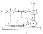
- the single drawing is a block diagram showing an embodiment of the method of controlling the motor speed in accordance with the present invention.
- the drawing shows the case where a DC motor 1 fed with a direct current of a desired level obtained by a gate turn-off thyristor 3 and speed-controlled through the negative feedback of a speed signal detected by a tachometer generator 4 is mounted on a supporting base 2 the position of which is changed during operation of the motor 1.
- the gate turn-off thyristor 3 receives an alternating current, rectifies it and feeds a direct current to the motor 1.
- a speed command signal A is compared with a speed signal B detected by the tachometer generator 4 driven by the motor 1.
- a speed error signal ihdicating the amount of deviation between the speed command signal A and the speed signal B is then amplified by an amplifying circuit 5 to generate a current command signal D.
- the current command signal D is then compared with a current signal E detected by a shunt circuit 6.
- a current error signal F indicating the amount of deviation between the current command signal D and the current signal E is amplified by an amplifying circuit 7 to generate a speed control signal G, which is then fed to the gate turn-off thyristor 3.
- An angular acceleration detecting means 8 comprising a rotary encoder, a resolver, or the like, and a differentiating circuit is supported on the supporting base 2 for detecting the degree of angular acceleration of the supporting base 2 in a plane normal to the shaft of the motor 1.
- angular velocity values detected by the rotary encoder, the resolver or the like are differentiated to obtain an angular acceleration signal H.
- the sign of the angular , acceleration signal H is reversed (e.g. a positive angular acceleration signal is converted to a negative acceleration signal) and compared, together with the speed command signal A, with the speed signal B to obtain the speed error signal C-
- the speed error signal C is processed as described above to control the speed of the motor 1.
- the speed command signal A for controlling the speed of the motor 1 is corrected on the basis of the angular acceleration signal H indicating the degree of angular acceleration of the supporting base 2, it is possible to eliminate the adverse effect of a change in the position of the supporting base 2 on the rotation speed of the motor 1.
Landscapes
- Engineering & Computer Science (AREA)
- Power Engineering (AREA)
- Control Of Electric Motors In General (AREA)
Applications Claiming Priority (2)
| Application Number | Priority Date | Filing Date | Title |
|---|---|---|---|
| JP58019838A JPS59148588A (ja) | 1983-02-10 | 1983-02-10 | 電動機の速度制御装置 |
| JP19838/83 | 1983-02-10 |
Publications (2)
| Publication Number | Publication Date |
|---|---|
| EP0116912A1 true EP0116912A1 (de) | 1984-08-29 |
| EP0116912B1 EP0116912B1 (de) | 1987-07-08 |
Family
ID=12010407
Family Applications (1)
| Application Number | Title | Priority Date | Filing Date |
|---|---|---|---|
| EP84101348A Expired EP0116912B1 (de) | 1983-02-10 | 1984-02-09 | Verfahren zur Regelung der Motorgeschwindigkeit |
Country Status (4)
| Country | Link |
|---|---|
| US (1) | US4803409A (de) |
| EP (1) | EP0116912B1 (de) |
| JP (1) | JPS59148588A (de) |
| DE (1) | DE3464679D1 (de) |
Cited By (1)
| Publication number | Priority date | Publication date | Assignee | Title |
|---|---|---|---|---|
| FR2637074A1 (fr) * | 1988-09-28 | 1990-03-30 | Hohner Automation Sa | Dispositif de determination simultanee d'une position, d'une vitesse, d'une acceleration et d'un sens de deplacement |
Families Citing this family (10)
| Publication number | Priority date | Publication date | Assignee | Title |
|---|---|---|---|---|
| JPS6198175A (ja) * | 1984-10-17 | 1986-05-16 | Matsushita Electric Ind Co Ltd | モ−タの制御装置 |
| US5049768A (en) * | 1987-07-15 | 1991-09-17 | The Boeing Company | Reducing engine noise by active oscillatory torque control |
| KR910009242B1 (ko) * | 1987-08-04 | 1991-11-07 | 가부시기가이샤 히다찌세이사꾸쇼 | 회전 전동기의 토오크 제어장치 |
| JP2814241B2 (ja) * | 1987-09-25 | 1998-10-22 | 株式会社ブリヂストン | 振動制御装置 |
| US5261026A (en) * | 1990-05-22 | 1993-11-09 | Kabushiki Kaisha Komatsu Seisakusho | Controlling apparatus for balanced cargo or work handling system |
| JPH0549106A (ja) * | 1991-08-09 | 1993-02-26 | Nissan Motor Co Ltd | モータ制御装置 |
| US7455711B1 (en) | 2006-06-16 | 2008-11-25 | Keystone Investment Corporation | Process for manufacturing hardened powder metal parts |
| JP5338449B2 (ja) * | 2009-04-22 | 2013-11-13 | コニカミノルタ株式会社 | アクチュエータおよび光学装置 |
| US11850662B1 (en) | 2015-02-09 | 2023-12-26 | Keystone Powdered Metal Company | High strength part having powder metal internal ring |
| CN111351998B (zh) * | 2019-12-25 | 2022-04-29 | 瑞声科技(新加坡)有限公司 | 一种马达极性确定方法、装置、存储介质及设备 |
Citations (4)
| Publication number | Priority date | Publication date | Assignee | Title |
|---|---|---|---|---|
| DE1017389B (de) * | 1956-09-19 | 1957-10-10 | Siemens Ag | Einrichtung zur Messung von Winkel-Beschleunigungen |
| GB1076624A (en) * | 1963-11-15 | 1967-07-19 | Materiel Electrique S W Le | Acceleration-control systems for direct-current motors |
| US3853002A (en) * | 1973-08-06 | 1974-12-10 | Autotronic Controls Corp | Vehicular performance analyzer |
| FR2402967A1 (fr) * | 1977-09-08 | 1979-04-06 | Fujitsu Fanuc Ltd | Dispositif de commande pour un moteur a courant continu |
Family Cites Families (13)
| Publication number | Priority date | Publication date | Assignee | Title |
|---|---|---|---|---|
| CH588779A5 (de) * | 1975-04-26 | 1977-06-15 | Papst Motoren Kg | |
| GB1538229A (en) * | 1975-05-01 | 1979-01-10 | Brown Bros & Co Ltd | Acceleration measuring devices |
| GB1516414A (en) * | 1975-08-22 | 1978-07-05 | Ici Ltd | Prostane derivatives |
| SE393909B (sv) * | 1975-09-24 | 1977-05-23 | Asea Ab | Stromriktare for anslutning till en vexelspenning och med likstromsuttag for anslutning till en belastning med en varierande emk |
| JPS6045804B2 (ja) * | 1978-02-28 | 1985-10-12 | 日本電気株式会社 | 角度検出器 |
| JPS54118259A (en) * | 1978-03-06 | 1979-09-13 | Nec Corp | Angle detector |
| JPS58722B2 (ja) * | 1978-06-23 | 1983-01-07 | 株式会社小松製作所 | 高速度鋼粉末の還元焼結方法 |
| JPS5944333B2 (ja) * | 1978-07-12 | 1984-10-29 | 富士写真フイルム株式会社 | 放射線像変換方法 |
| JPS5686083A (en) * | 1979-12-13 | 1981-07-13 | Trio Kenwood Corp | Controlling device for motor |
| JPS56104645A (en) * | 1979-12-25 | 1981-08-20 | Fuji Photo Film Co Ltd | Radiation picture treating method and its device |
| JPS5719700A (en) * | 1980-07-10 | 1982-02-01 | Fuji Photo Film Co Ltd | Radiation image information reading gain controller |
| JPS5719376A (en) * | 1980-07-10 | 1982-02-01 | Nippon Telegr & Teleph Corp <Ntt> | Plasma etching method |
| JPS57208891A (en) * | 1981-06-17 | 1982-12-22 | Yaskawa Electric Mfg Co Ltd | Control system of motor driven machine |
-
1983
- 1983-02-10 JP JP58019838A patent/JPS59148588A/ja active Pending
-
1984
- 1984-02-09 EP EP84101348A patent/EP0116912B1/de not_active Expired
- 1984-02-09 DE DE8484101348T patent/DE3464679D1/de not_active Expired
-
1987
- 1987-06-01 US US07/055,886 patent/US4803409A/en not_active Expired - Lifetime
Patent Citations (4)
| Publication number | Priority date | Publication date | Assignee | Title |
|---|---|---|---|---|
| DE1017389B (de) * | 1956-09-19 | 1957-10-10 | Siemens Ag | Einrichtung zur Messung von Winkel-Beschleunigungen |
| GB1076624A (en) * | 1963-11-15 | 1967-07-19 | Materiel Electrique S W Le | Acceleration-control systems for direct-current motors |
| US3853002A (en) * | 1973-08-06 | 1974-12-10 | Autotronic Controls Corp | Vehicular performance analyzer |
| FR2402967A1 (fr) * | 1977-09-08 | 1979-04-06 | Fujitsu Fanuc Ltd | Dispositif de commande pour un moteur a courant continu |
Cited By (1)
| Publication number | Priority date | Publication date | Assignee | Title |
|---|---|---|---|---|
| FR2637074A1 (fr) * | 1988-09-28 | 1990-03-30 | Hohner Automation Sa | Dispositif de determination simultanee d'une position, d'une vitesse, d'une acceleration et d'un sens de deplacement |
Also Published As
| Publication number | Publication date |
|---|---|
| DE3464679D1 (en) | 1987-08-13 |
| US4803409A (en) | 1989-02-07 |
| EP0116912B1 (de) | 1987-07-08 |
| JPS59148588A (ja) | 1984-08-25 |
Similar Documents
| Publication | Publication Date | Title |
|---|---|---|
| US6515442B1 (en) | Position controller | |
| EP0116912B1 (de) | Verfahren zur Regelung der Motorgeschwindigkeit | |
| KR930008780B1 (ko) | 이동체의 속도제어장치 | |
| US5006770A (en) | Servomotor velocity control apparatus | |
| US4087731A (en) | Control system for moving a large machine along a single axis | |
| JPS6129302B2 (de) | ||
| EP0347465A1 (de) | Verfahren zur steuerung eines servomotors | |
| EP0176470B1 (de) | Vorrichtung zum Zerschneiden einer Platte in Abschnitte vorbestimmter Grösse | |
| JPS6130514B2 (de) | ||
| JPS61203885A (ja) | モ−タ制御方式 | |
| JPS5690452A (en) | Reel control system | |
| JPS63110988A (ja) | 回転速度制御装置 | |
| JP3252427B2 (ja) | サーボモータの制御装置 | |
| JPS58144582A (ja) | サ−ボモ−タ制御装置 | |
| JP2607608B2 (ja) | テープ速度制御装置 | |
| JPH0446576A (ja) | モータの回転速度制御回路 | |
| SU1413596A1 (ru) | След ща система | |
| JPS63209499A (ja) | 電動機の制御装置 | |
| JPS59133604A (ja) | 張力制御装置 | |
| JPH069438B2 (ja) | モ−タの制御装置 | |
| JPH027112A (ja) | オフセット補正制御方式 | |
| JPS58108983A (ja) | モ−タ制御装置 | |
| JPS58177255U (ja) | 加工ユニツトの駆動制御装置 | |
| JPH06141578A (ja) | 速度制御装置 | |
| JPS5864505A (ja) | サ−ボ系の帰還制御回路 |
Legal Events
| Date | Code | Title | Description |
|---|---|---|---|
| PUAI | Public reference made under article 153(3) epc to a published international application that has entered the european phase |
Free format text: ORIGINAL CODE: 0009012 |
|
| AK | Designated contracting states |
Designated state(s): DE FR NL |
|
| 17P | Request for examination filed |
Effective date: 19841022 |
|
| GRAA | (expected) grant |
Free format text: ORIGINAL CODE: 0009210 |
|
| AK | Designated contracting states |
Kind code of ref document: B1 Designated state(s): DE FR NL |
|
| REF | Corresponds to: |
Ref document number: 3464679 Country of ref document: DE Date of ref document: 19870813 |
|
| ET | Fr: translation filed | ||
| PLBE | No opposition filed within time limit |
Free format text: ORIGINAL CODE: 0009261 |
|
| STAA | Information on the status of an ep patent application or granted ep patent |
Free format text: STATUS: NO OPPOSITION FILED WITHIN TIME LIMIT |
|
| 26N | No opposition filed | ||
| PGFP | Annual fee paid to national office [announced via postgrant information from national office to epo] |
Ref country code: NL Payment date: 20030217 Year of fee payment: 20 |
|
| PGFP | Annual fee paid to national office [announced via postgrant information from national office to epo] |
Ref country code: FR Payment date: 20030218 Year of fee payment: 20 |
|
| PGFP | Annual fee paid to national office [announced via postgrant information from national office to epo] |
Ref country code: DE Payment date: 20030428 Year of fee payment: 20 |
|
| PG25 | Lapsed in a contracting state [announced via postgrant information from national office to epo] |
Ref country code: NL Free format text: LAPSE BECAUSE OF EXPIRATION OF PROTECTION Effective date: 20040209 |
|
| NLV7 | Nl: ceased due to reaching the maximum lifetime of a patent |
Effective date: 20040209 |