EP0117166A1 - Endstücksstreifen eines elektrischen Kabels, dessen Herstellungverfahren und Anwendung für die Herstellung elektrischer Drähte ausgerüstet mit einem Endstück oder einem Kabelschuh - Google Patents
Endstücksstreifen eines elektrischen Kabels, dessen Herstellungverfahren und Anwendung für die Herstellung elektrischer Drähte ausgerüstet mit einem Endstück oder einem Kabelschuh Download PDFInfo
- Publication number
- EP0117166A1 EP0117166A1 EP19840400045 EP84400045A EP0117166A1 EP 0117166 A1 EP0117166 A1 EP 0117166A1 EP 19840400045 EP19840400045 EP 19840400045 EP 84400045 A EP84400045 A EP 84400045A EP 0117166 A1 EP0117166 A1 EP 0117166A1
- Authority
- EP
- European Patent Office
- Prior art keywords
- head
- neck
- chute
- end piece
- strip
- Prior art date
- Legal status (The legal status is an assumption and is not a legal conclusion. Google has not performed a legal analysis and makes no representation as to the accuracy of the status listed.)
- Granted
Links
- 239000004020 conductor Substances 0.000 title claims abstract description 20
- 238000004519 manufacturing process Methods 0.000 title claims description 27
- 238000000034 method Methods 0.000 title claims description 15
- 239000002184 metal Substances 0.000 claims abstract description 11
- 238000002788 crimping Methods 0.000 claims abstract description 10
- 239000000463 material Substances 0.000 claims abstract description 9
- 238000005520 cutting process Methods 0.000 claims description 7
- 238000004873 anchoring Methods 0.000 claims description 3
- 210000002105 tongue Anatomy 0.000 description 5
- 208000031968 Cadaver Diseases 0.000 description 1
- 238000005452 bending Methods 0.000 description 1
- 239000000470 constituent Substances 0.000 description 1
- 230000003100 immobilizing effect Effects 0.000 description 1
- 238000003780 insertion Methods 0.000 description 1
- 230000037431 insertion Effects 0.000 description 1
- 238000012986 modification Methods 0.000 description 1
- 230000004048 modification Effects 0.000 description 1
- 238000010137 moulding (plastic) Methods 0.000 description 1
Images


Classifications
-
- H—ELECTRICITY
- H01—ELECTRIC ELEMENTS
- H01R—ELECTRICALLY-CONDUCTIVE CONNECTIONS; STRUCTURAL ASSOCIATIONS OF A PLURALITY OF MUTUALLY-INSULATED ELECTRICAL CONNECTING ELEMENTS; COUPLING DEVICES; CURRENT COLLECTORS
- H01R11/00—Individual connecting elements providing two or more spaced connecting locations for conductive members which are, or may be, thereby interconnected, e.g. end pieces for wires or cables supported by the wire or cable and having means for facilitating electrical connection to some other wire, terminal, or conductive member, blocks of binding posts
- H01R11/11—End pieces or tapping pieces for wires, supported by the wire and for facilitating electrical connection to some other wire, terminal or conductive member
-
- H—ELECTRICITY
- H01—ELECTRIC ELEMENTS
- H01R—ELECTRICALLY-CONDUCTIVE CONNECTIONS; STRUCTURAL ASSOCIATIONS OF A PLURALITY OF MUTUALLY-INSULATED ELECTRICAL CONNECTING ELEMENTS; COUPLING DEVICES; CURRENT COLLECTORS
- H01R43/00—Apparatus or processes specially adapted for manufacturing, assembling, maintaining, or repairing of line connectors or current collectors or for joining electric conductors
- H01R43/16—Apparatus or processes specially adapted for manufacturing, assembling, maintaining, or repairing of line connectors or current collectors or for joining electric conductors for manufacturing contact members, e.g. by punching and by bending
-
- H—ELECTRICITY
- H01—ELECTRIC ELEMENTS
- H01R—ELECTRICALLY-CONDUCTIVE CONNECTIONS; STRUCTURAL ASSOCIATIONS OF A PLURALITY OF MUTUALLY-INSULATED ELECTRICAL CONNECTING ELEMENTS; COUPLING DEVICES; CURRENT COLLECTORS
- H01R43/00—Apparatus or processes specially adapted for manufacturing, assembling, maintaining, or repairing of line connectors or current collectors or for joining electric conductors
- H01R43/20—Apparatus or processes specially adapted for manufacturing, assembling, maintaining, or repairing of line connectors or current collectors or for joining electric conductors for assembling or disassembling contact members with insulating base, case or sleeve
- H01R43/24—Assembling by moulding on contact members
Definitions
- the invention relates to strip ends for electrical conductors, the method for manufacturing these ends and their application to the mass production of conductive wires fitted with ends or terminals produced according to the method.
- Patent FR 2 468 224 discloses a method of manufacturing band end caps, but this process seems difficult to automate, because it is necessary to introduce the tubes of the end sleeves on cores in order to be able to overmold the insulating sheath and the strip portions connecting several end caps.
- the object of the invention is to avoid these drawbacks and to allow automated manufacture of strip end caps, and its application to the mass production of conductive wires fitted with end caps or terminals.
- Another object of the invention is to allow the manufacture of end pieces from a metal strip, which reduces the manufacturing cost, while providing end pieces which can be supplied in strip form.
- a final object of the invention is to obtain band ends using the least number of parts possible and to provide a manufacturing process using the lowest possible number of steps and rework of parts.
- a ferrule for multi-stranded conductor cable intended for crimping multi-stranded conductors, is characterized in that it comprises a shape cut from a metal strip having a rectangular body shaped as a trough, a head overmolded in plastic material and shaped at least in a chute, and a collar connecting the body to the head.
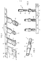
- FIG. 1 represents a first embodiment of the end piece and the different stages of the manufacturing process.
- the end piece is obtained from an electrically conductive metal strip cut according to the shape shown in step A of the process.
- This form 1 comprises a main body 10 of rectangular shape, a head 11 comprising dovetail cutouts 12; this head is connected to the body 10 by a neck 13.
- the entire cutout constituting the end piece is connected to the edge of the metal strip 14 by an appendage 15.
- the strip driven by the holes 19 will pass through stations successive work where she will undergo operations B, C, D, E, F, G.
- the head 11 and the body 10 are given a form of trough by stamping. This constitutes the second phase B of the process.
- the head 11 is given the shape of a split crown or ring shown in step C.
- step D the strip end pieces are introduced into a plastic molding machine which overmoulds the head 11 with an insulating plastic material 16. Continuous strip end pieces are thus obtained, the appendages 15 of which can be possibly cut if you want to deliver the tips in bulk.
- a final step E is added when it is desired to obtain multi-strand conductive cables 2 coated with an insulating sheath 20, these cables being fitted with end caps at their ends, as shown in FIG. 2.
- This last phase includes step E shown in Figure 3, on which we can see a strip of tips overmolded at the insertion station for multi-strand conductor cables 2.
- the conductive cables 2 previously cut to standardized lengths and stripped at their ends, are introduced axially into the overmolded cylindrical head, until the sheath 20 abuts against the bosses 161 shown in FIG. 4.
- the multi-strand conductors 21 are then facing the conductive portion of the body 10, then are crimped in the end piece in step F.
- step G which is optional, the conductors fitted with end caps are separated from the strip by cutting off appendix 15.
- the dovetail teeth 12 are slightly flared at an angle of the order of 30 °, as shown in FIG. 4.
- the conicity given to the teeth 12 makes it possible to obtain a good anchoring of the metal part of the nozzle in the overmolded plastic.
- the overmolded part 16 comprises a conical portion 163 for guiding the multi-strands, as well as a cylindrical portion 164 provided with internal bosses 161 for immobilizing the insulating sheath of the conductive cable.
- a tongue forming a hook 162 intended to receive index markers.
- Such a tongue is well known to those skilled in the art and already described in Patent FR 1,468,859.
- FIG. 5 represents a second embodiment of the end pieces and the different stages of the method.
- the strip is brought to a station where the piece 1 undergoes a stamping operation, so as to give said piece the shape of a chute, as shown in step B.
- each part or set of parts is subjected to an overmolding operation C, with plastic material, of all or part of the head 11.
- a conductive cable 2, stripped on a portion 21, falls vertically into the trough of each piece 1, so that the insulating part 20 of the cable coincides with the overmolded portion 16 and that the stripped portion 18 is opposite the conductive portion 10 of the nozzle.
- This operation is followed by the crimping operation of one or more end caps, shown in step E.
- the metal part 10 is crimped onto the multi-strand conductor 21, while the overmolded part tightens the sheath insulating 20.
- This operation G can be followed by an operation G, not shown, of cutting the appendix 15.
- FIG. 6 a distinction is made between the axial offset between the portion 11 and the portion 10, which is necessary so that the axis of the conductive strands merges with that of the insulating sheath 20.
- This offset is obtained during the stamping operation B, by deformation of the neck 13 connecting the body 10 to the head 11.
- the overmolded plastic material 16 is anchored on the head by the holes 12.
- a tab 162 serving as an index holder.
- FIG. 7a represents a variant of a nozzle obtained according to the first embodiment with, in place of the tongue 162, a rectangular opening 165 allowing the fixing of a label-carrying tongue not shown and of the type mentioned above .
- Figures 8, 9, 10, 11 show different applications of the ends obtained according to the second embodiment for obtaining end caps.
- the tips in which there are the various constituent parts; 16 the overmolded part; 10 the crimpable part and 13 the junction neck (not shown) between the two parts 16 and 10, are extended by a second junction neck 30 of the crimpable part to a portion 31, 32, 33 or 34 constituting a connection terminal .
- This portion of junction terminal can have, as shown in Figures 8, 9, 10, 11, any shape allowing to achieve all types of fixing and connection that is desired.
- the lugs 31 and 32 allow a connection by screws, while the lugs 33 and 34 of the type known in the Anglo-Saxon literature under the name of "fast-on” allow a connection by tightening.
- the shapes of the lugs 31, 32, 33, 34 are obtained, during the manufacturing process, by cutting and bending the metal strip and are connected to the strip by the tongues 15.
- the same process for manufacturing the ends assembled in series on conductor cables of standard length applies to terminal lugs. It is therefore sufficient to provide, in the manufacturing operations, for the cutting operations of the second neck 30 and of the second body 31, 32, 33, 34 as well as the lug-shaped forming operations.
- the overmolded parts can also be provided with label holder means.
- the overmolded part instead of obtaining an overmolded element in the form of a chute, the overmolded part will be cylindrical as in step D of FIG. 1.
- the other parts 31 to 34 will be identical and connected by a neck 30 to the part crimpable.
Landscapes
- Manufacturing Of Electrical Connectors (AREA)
- Connections Effected By Soldering, Adhesion, Or Permanent Deformation (AREA)
- Multi-Conductor Connections (AREA)
Applications Claiming Priority (2)
| Application Number | Priority Date | Filing Date | Title |
|---|---|---|---|
| FR8300374 | 1983-01-12 | ||
| FR8300374A FR2539252A1 (fr) | 1983-01-12 | 1983-01-12 | Embout en bande pour conducteur electrique, son procede de fabrication et son application a la fabrication de fils conducteurs munis d'un embout ou d'une cosse |
Publications (2)
| Publication Number | Publication Date |
|---|---|
| EP0117166A1 true EP0117166A1 (de) | 1984-08-29 |
| EP0117166B1 EP0117166B1 (de) | 1987-04-01 |
Family
ID=9284860
Family Applications (1)
| Application Number | Title | Priority Date | Filing Date |
|---|---|---|---|
| EP19840400045 Expired EP0117166B1 (de) | 1983-01-12 | 1984-01-10 | Endstücksstreifen eines elektrischen Kabels, dessen Herstellungverfahren und Anwendung für die Herstellung elektrischer Drähte ausgerüstet mit einem Endstück oder einem Kabelschuh |
Country Status (5)
| Country | Link |
|---|---|
| EP (1) | EP0117166B1 (de) |
| JP (1) | JPS59138080A (de) |
| DE (1) | DE3462973D1 (de) |
| ES (2) | ES8503894A1 (de) |
| FR (1) | FR2539252A1 (de) |
Cited By (5)
| Publication number | Priority date | Publication date | Assignee | Title |
|---|---|---|---|---|
| GB2173053A (en) * | 1985-03-27 | 1986-10-01 | Telemecanique Electrique | An electrical conductor socket terminal and method of producing the same |
| FR2626113A1 (fr) * | 1988-01-15 | 1989-07-21 | Legrand Sa | Accessoire de cablage a fut ferme |
| US4861280A (en) * | 1987-06-19 | 1989-08-29 | Grafoplast S.P.A. | Electric cable terminal consisting of two independent elements to be assembled by axial sliding |
| EP0335772A1 (de) * | 1988-03-29 | 1989-10-04 | Legrand | Kabelendstück |
| CN102544788A (zh) * | 2012-01-20 | 2012-07-04 | 孙庆华 | 一种安保插及其装配方法 |
Families Citing this family (3)
| Publication number | Priority date | Publication date | Assignee | Title |
|---|---|---|---|---|
| JPS6412383U (de) * | 1987-07-14 | 1989-01-23 | ||
| JP5430274B2 (ja) | 2009-07-31 | 2014-02-26 | 矢崎総業株式会社 | 連鎖端子 |
| JP5711790B2 (ja) * | 2013-08-05 | 2015-05-07 | 矢崎総業株式会社 | 電線に接続された端子を製造する製造方法 |
Citations (6)
| Publication number | Priority date | Publication date | Assignee | Title |
|---|---|---|---|---|
| US2861324A (en) * | 1954-12-16 | 1958-11-25 | Jr Ferdinand Klumpp | Method of making an electrical conductor terminal |
| DE1065908B (de) * | 1959-09-24 | |||
| FR1468859A (fr) * | 1965-10-20 | 1967-02-10 | Telemecanique Electrique | Embout perfectionné pour raccordement de conducteur électrique |
| GB1379993A (en) * | 1972-04-07 | 1975-01-08 | Pressac Ltd | Method of applying an electric terminal to a cable |
| GB1455324A (en) * | 1973-02-01 | 1976-11-10 | Itt | Electrical connector |
| FR2468224A1 (fr) * | 1979-10-16 | 1981-04-30 | Weidmueller Kg C | Procede et dispositif pour la fabrication de contacts avec connexion par sertissage |
Family Cites Families (2)
| Publication number | Priority date | Publication date | Assignee | Title |
|---|---|---|---|---|
| JPS5621230B2 (de) * | 1972-11-24 | 1981-05-18 | ||
| JPS595887Y2 (ja) * | 1981-06-29 | 1984-02-22 | 晴生 野山 | 広告灯 |
-
1983
- 1983-01-12 FR FR8300374A patent/FR2539252A1/fr active Granted
-
1984
- 1984-01-10 DE DE8484400045T patent/DE3462973D1/de not_active Expired
- 1984-01-10 EP EP19840400045 patent/EP0117166B1/de not_active Expired
- 1984-01-11 JP JP335684A patent/JPS59138080A/ja active Granted
- 1984-01-12 ES ES528831A patent/ES8503894A1/es not_active Expired
- 1984-09-28 ES ES1984281654U patent/ES281654Y/es not_active Expired
Patent Citations (6)
| Publication number | Priority date | Publication date | Assignee | Title |
|---|---|---|---|---|
| DE1065908B (de) * | 1959-09-24 | |||
| US2861324A (en) * | 1954-12-16 | 1958-11-25 | Jr Ferdinand Klumpp | Method of making an electrical conductor terminal |
| FR1468859A (fr) * | 1965-10-20 | 1967-02-10 | Telemecanique Electrique | Embout perfectionné pour raccordement de conducteur électrique |
| GB1379993A (en) * | 1972-04-07 | 1975-01-08 | Pressac Ltd | Method of applying an electric terminal to a cable |
| GB1455324A (en) * | 1973-02-01 | 1976-11-10 | Itt | Electrical connector |
| FR2468224A1 (fr) * | 1979-10-16 | 1981-04-30 | Weidmueller Kg C | Procede et dispositif pour la fabrication de contacts avec connexion par sertissage |
Cited By (9)
| Publication number | Priority date | Publication date | Assignee | Title |
|---|---|---|---|---|
| GB2173053A (en) * | 1985-03-27 | 1986-10-01 | Telemecanique Electrique | An electrical conductor socket terminal and method of producing the same |
| DE3610086A1 (de) * | 1985-03-27 | 1986-10-02 | La Télémécanique Electrique S.A., Nanterre, Hauts-de-Seine | Endstueck fuer einen elektrischen leiter und verfahren zur herstellung desselben |
| FR2579836A1 (fr) * | 1985-03-27 | 1986-10-03 | Telemecanique Electrique | Embout pour conducteur electrique et son procede de fabrication |
| US4861280A (en) * | 1987-06-19 | 1989-08-29 | Grafoplast S.P.A. | Electric cable terminal consisting of two independent elements to be assembled by axial sliding |
| FR2626113A1 (fr) * | 1988-01-15 | 1989-07-21 | Legrand Sa | Accessoire de cablage a fut ferme |
| EP0335772A1 (de) * | 1988-03-29 | 1989-10-04 | Legrand | Kabelendstück |
| FR2629646A1 (fr) * | 1988-03-29 | 1989-10-06 | Legrand Sa | Embout de cablage |
| US4969845A (en) * | 1988-03-29 | 1990-11-13 | Legrand | Electric terminal connector |
| CN102544788A (zh) * | 2012-01-20 | 2012-07-04 | 孙庆华 | 一种安保插及其装配方法 |
Also Published As
| Publication number | Publication date |
|---|---|
| ES528831A0 (es) | 1985-03-01 |
| ES281654U (es) | 1985-11-16 |
| ES8503894A1 (es) | 1985-03-01 |
| FR2539252B1 (de) | 1985-03-22 |
| JPS59138080A (ja) | 1984-08-08 |
| ES281654Y (es) | 1986-06-01 |
| DE3462973D1 (en) | 1987-05-07 |
| EP0117166B1 (de) | 1987-04-01 |
| FR2539252A1 (fr) | 1984-07-13 |
| JPH0443395B2 (de) | 1992-07-16 |
Similar Documents
| Publication | Publication Date | Title |
|---|---|---|
| US5749756A (en) | Sealed corrosion-proof crimped terminal of splice | |
| KR100768990B1 (ko) | 방수형 리드 제조용 지그 | |
| CN102782942B (zh) | 压接端子与电线的连接结构 | |
| FR2667448A1 (fr) | Connecteur soude pour cable coaxial blinde. | |
| EP3155692B1 (de) | Abgeschirmter elektrischer verbinder und herstellungsverfahren davon | |
| FR2510312A1 (fr) | Connecteur de blindage pour cables blindes | |
| EP0117166B1 (de) | Endstücksstreifen eines elektrischen Kabels, dessen Herstellungverfahren und Anwendung für die Herstellung elektrischer Drähte ausgerüstet mit einem Endstück oder einem Kabelschuh | |
| JPH07153502A (ja) | 圧着端子組立体 | |
| CA2443597C (en) | Terminal of a medium voltage electrical cable | |
| JP2004273333A (ja) | フラットケーブル | |
| EP0209452B1 (de) | Mehrzweck-Steckverbinder für das Anschliessen von verschiedenen Kabeltypen oder elektrischer Leiter | |
| EP0134742B1 (de) | Vorrichtung zum Anschluss eines Bündels elektrischer Drähte, und Herstellungsverfahren | |
| FR2579836A1 (fr) | Embout pour conducteur electrique et son procede de fabrication | |
| EP0718915B1 (de) | Verbindungselement mit isolationsdurchtrennendem Schlitz, insbesondere für Telefon- oder Datenübertragungs-Reihenklemmen, dessen Herstellung und Reihenklemme mit mindestens einem solchen Verbindungselement | |
| FR2633103A1 (fr) | Embout de cablage | |
| FR3028677A1 (fr) | Assemblage d'un ensemble de raccordement electrique | |
| EP3349305B1 (de) | Verbessertes elektrisches anschlusskit | |
| EP0820117A1 (de) | Vorrichtung zur Herstellung eines Spleisses | |
| JP3415426B2 (ja) | コネクタにおけるコード線の外皮の剥離装置およびコネクタにおけるコード線の芯線と接触端子との接続方法 | |
| JP2000123889A (ja) | 電気接続端子及び電気コネクタ | |
| FR2582159A1 (fr) | Dispositif d'etancheite de raccordement de conducteurs electriques sur un element de boitier de connecteur et procede de fabrication dudit dispositif | |
| JP6056062B2 (ja) | 圧着端子 | |
| FR2715000A1 (fr) | Procédé de fabrication de conducteurs auto-protégés. | |
| EP0406501A1 (de) | Anschlussklemme für eine Wicklung auf einem Spulenkörper und Verfahren zur Herstellung einer Wicklung auf einem Spulenkörper, welcher mit solchen Anschlussklemmen versehen ist. | |
| EP0268502B1 (de) | Klammerförmiges Kabelendstück für Zündverteilerdeckel |
Legal Events
| Date | Code | Title | Description |
|---|---|---|---|
| PUAI | Public reference made under article 153(3) epc to a published international application that has entered the european phase |
Free format text: ORIGINAL CODE: 0009012 |
|
| 17P | Request for examination filed |
Effective date: 19840111 |
|
| AK | Designated contracting states |
Designated state(s): BE DE GB IT LU NL |
|
| GRAA | (expected) grant |
Free format text: ORIGINAL CODE: 0009210 |
|
| AK | Designated contracting states |
Kind code of ref document: B1 Designated state(s): BE DE GB IT LU NL |
|
| ITF | It: translation for a ep patent filed | ||
| REF | Corresponds to: |
Ref document number: 3462973 Country of ref document: DE Date of ref document: 19870507 |
|
| RIN2 | Information on inventor provided after grant (corrected) |
Free format text: SAUTHIER, LUCIEN * JUNIN, MICHEL * LADIRE, ALAIN |
|
| PLBE | No opposition filed within time limit |
Free format text: ORIGINAL CODE: 0009261 |
|
| STAA | Information on the status of an ep patent application or granted ep patent |
Free format text: STATUS: NO OPPOSITION FILED WITHIN TIME LIMIT |
|
| 26N | No opposition filed | ||
| ITTA | It: last paid annual fee | ||
| EPTA | Lu: last paid annual fee | ||
| PGFP | Annual fee paid to national office [announced via postgrant information from national office to epo] |
Ref country code: NL Payment date: 19951215 Year of fee payment: 13 |
|
| PGFP | Annual fee paid to national office [announced via postgrant information from national office to epo] |
Ref country code: LU Payment date: 19960101 Year of fee payment: 13 |
|
| PGFP | Annual fee paid to national office [announced via postgrant information from national office to epo] |
Ref country code: GB Payment date: 19960102 Year of fee payment: 13 |
|
| PGFP | Annual fee paid to national office [announced via postgrant information from national office to epo] |
Ref country code: DE Payment date: 19960120 Year of fee payment: 13 |
|
| PGFP | Annual fee paid to national office [announced via postgrant information from national office to epo] |
Ref country code: BE Payment date: 19960212 Year of fee payment: 13 |
|
| PG25 | Lapsed in a contracting state [announced via postgrant information from national office to epo] |
Ref country code: LU Free format text: LAPSE BECAUSE OF NON-PAYMENT OF DUE FEES Effective date: 19970110 Ref country code: GB Effective date: 19970110 |
|
| PG25 | Lapsed in a contracting state [announced via postgrant information from national office to epo] |
Ref country code: BE Effective date: 19970131 |
|
| BERE | Be: lapsed |
Owner name: LA TELEMECANIQUE ELECTRIQUE Effective date: 19970131 |
|
| PG25 | Lapsed in a contracting state [announced via postgrant information from national office to epo] |
Ref country code: NL Effective date: 19970801 |
|
| GBPC | Gb: european patent ceased through non-payment of renewal fee |
Effective date: 19970110 |
|
| NLV4 | Nl: lapsed or anulled due to non-payment of the annual fee |
Effective date: 19970801 |
|
| PG25 | Lapsed in a contracting state [announced via postgrant information from national office to epo] |
Ref country code: DE Effective date: 19971001 |