EP0117192A1 - Scheibenbremse - Google Patents
Scheibenbremse Download PDFInfo
- Publication number
- EP0117192A1 EP0117192A1 EP84400261A EP84400261A EP0117192A1 EP 0117192 A1 EP0117192 A1 EP 0117192A1 EP 84400261 A EP84400261 A EP 84400261A EP 84400261 A EP84400261 A EP 84400261A EP 0117192 A1 EP0117192 A1 EP 0117192A1
- Authority
- EP
- European Patent Office
- Prior art keywords
- stirrup
- disc
- retaining
- caliper
- bar
- Prior art date
- Legal status (The legal status is an assumption and is not a legal conclusion. Google has not performed a legal analysis and makes no representation as to the accuracy of the status listed.)
- Granted
Links
Images
Classifications
-
- F—MECHANICAL ENGINEERING; LIGHTING; HEATING; WEAPONS; BLASTING
- F16—ENGINEERING ELEMENTS AND UNITS; GENERAL MEASURES FOR PRODUCING AND MAINTAINING EFFECTIVE FUNCTIONING OF MACHINES OR INSTALLATIONS; THERMAL INSULATION IN GENERAL
- F16D—COUPLINGS FOR TRANSMITTING ROTATION; CLUTCHES; BRAKES
- F16D55/00—Brakes with substantially-radial braking surfaces pressed together in axial direction, e.g. disc brakes
- F16D55/02—Brakes with substantially-radial braking surfaces pressed together in axial direction, e.g. disc brakes with axially-movable discs or pads pressed against axially-located rotating members
- F16D55/22—Brakes with substantially-radial braking surfaces pressed together in axial direction, e.g. disc brakes with axially-movable discs or pads pressed against axially-located rotating members by clamping an axially-located rotating disc between movable braking members, e.g. movable brake discs or brake pads
- F16D55/224—Brakes with substantially-radial braking surfaces pressed together in axial direction, e.g. disc brakes with axially-movable discs or pads pressed against axially-located rotating members by clamping an axially-located rotating disc between movable braking members, e.g. movable brake discs or brake pads with a common actuating member for the braking members
- F16D55/225—Brakes with substantially-radial braking surfaces pressed together in axial direction, e.g. disc brakes with axially-movable discs or pads pressed against axially-located rotating members by clamping an axially-located rotating disc between movable braking members, e.g. movable brake discs or brake pads with a common actuating member for the braking members the braking members being brake pads
- F16D55/226—Brakes with substantially-radial braking surfaces pressed together in axial direction, e.g. disc brakes with axially-movable discs or pads pressed against axially-located rotating members by clamping an axially-located rotating disc between movable braking members, e.g. movable brake discs or brake pads with a common actuating member for the braking members the braking members being brake pads in which the common actuating member is moved axially, e.g. floating caliper disc brakes
- F16D55/2265—Brakes with substantially-radial braking surfaces pressed together in axial direction, e.g. disc brakes with axially-movable discs or pads pressed against axially-located rotating members by clamping an axially-located rotating disc between movable braking members, e.g. movable brake discs or brake pads with a common actuating member for the braking members the braking members being brake pads in which the common actuating member is moved axially, e.g. floating caliper disc brakes the axial movement being guided by one or more pins engaging bores in the brake support or the brake housing
-
- F—MECHANICAL ENGINEERING; LIGHTING; HEATING; WEAPONS; BLASTING
- F16—ENGINEERING ELEMENTS AND UNITS; GENERAL MEASURES FOR PRODUCING AND MAINTAINING EFFECTIVE FUNCTIONING OF MACHINES OR INSTALLATIONS; THERMAL INSULATION IN GENERAL
- F16D—COUPLINGS FOR TRANSMITTING ROTATION; CLUTCHES; BRAKES
- F16D55/00—Brakes with substantially-radial braking surfaces pressed together in axial direction, e.g. disc brakes
- F16D55/24—Brakes with substantially-radial braking surfaces pressed together in axial direction, e.g. disc brakes with a plurality of axially-movable discs, lamellae, or pads, pressed from one side towards an axially-located member
- F16D55/26—Brakes with substantially-radial braking surfaces pressed together in axial direction, e.g. disc brakes with a plurality of axially-movable discs, lamellae, or pads, pressed from one side towards an axially-located member without self-tightening action
- F16D55/36—Brakes with a plurality of rotating discs all lying side by side
- F16D55/40—Brakes with a plurality of rotating discs all lying side by side actuated by a fluid-pressure device arranged in or one the brake
-
- F—MECHANICAL ENGINEERING; LIGHTING; HEATING; WEAPONS; BLASTING
- F16—ENGINEERING ELEMENTS AND UNITS; GENERAL MEASURES FOR PRODUCING AND MAINTAINING EFFECTIVE FUNCTIONING OF MACHINES OR INSTALLATIONS; THERMAL INSULATION IN GENERAL
- F16D—COUPLINGS FOR TRANSMITTING ROTATION; CLUTCHES; BRAKES
- F16D55/00—Brakes with substantially-radial braking surfaces pressed together in axial direction, e.g. disc brakes
- F16D2055/0004—Parts or details of disc brakes
- F16D2055/0062—Partly lined, i.e. braking surface extending over only a part of the disc circumference
Definitions
- the present invention relates to a disc brake of the type comprising at least one rotary brake disc; friction pads arranged on either side of the brake disc and capable of being applied against the lateral faces of said disc, each of these pads comprising a friction lining and a lining carrier plate; a fixed support having at least one lateral flange parallel to the brake disc provided with a central recess, transverse end arms extending parallel to the axis of the brake disc over a part of the periphery of the brake disc, and transverse guide means for supporting the friction pads and guiding their movement parallel to the axis of the brake disc; a stirrup which, seen in the forward direction, is mounted, on the inside, on the rear transverse arm of the fixed support using a small column so as to be able to pivot around an axis parallel to that of the disc brake and slide along this baluster which is integral with the caliper or rear arm and slides in a bore provided in said rear arm or said caliper, the caliper covering the friction pads and the part of the disc
- This type of brake is known, for example, from French patents 2 342 43I and 2 478 761 and has the drawback either of having locking means only for the caliper, or of requiring locking means separate for the friction pads in their guide housings, on the one hand, and for the caliper, on the other hand.
- the friction pads are not kept in permanent contact with their corresponding guide housings.
- the number of additional organs is increased.
- the implementation of the locking means requires special arrangements both on the stirrup and on the front arm of the fixed support.
- the object of the present invention is to eliminate these drawbacks and to propose a disc brake which ensures with simple means an effective locking of the friction pads and the caliper, it being understood that this locking must allow the translational movements of the pads and of the caliper parallel to the axes of the brake disc and of the single baluster.
- the lining carrier plates comprise, at both front and rear ends, near their upper edge, support and locking spouts overhanging a retaining notch, that the end arms have on the inner side of the central recess of the fixed support a guide and locking bar overhanging the central recess, that in the locking position, the underside of the front guide bar and the corresponding face of the retaining notch before the carrier plates delimit between them a blocking interval in which a retaining key is inserted, that the front end of the stirrup has a blocking notch whose active face is in the working position bracket, parallel to the underside of the front bar, aligned with the inclined face of the front retaining notches, and cooperates with the retaining key in an area close to the lining carrier plate of one of the friction pads.
- part (the front bar and the retaining key) of the locking means of the friction pads serves at the same time as a locking member in the locking means of the caliper.
- This design not only simplifies the mounting of the brake or the replacement of worn parts of said brake, but virtually also removes any forgetting of locking.
- the subject of the invention is particularly advantageous for multi-risk brakes.
- each guide and locking bar has the shape of a dihedron whose angle is acute and whose upper face is perpendicular to the radial median plane of the brake and the retaining notches of the carrier plates have a corresponding shape.
- the stirrup blocking notch also has the form of a dihedral whose angle is acute and identical to that of the front bar of the fixed support.
- the stirrup blocking notch is formed in a frontal protuberance of the stirrup located in front of and, seen in height, on either side of the dihedral edge of the front bar when the stirrup is in working position.
- the retaining key advantageously has the form of a dihedron whose angle is identical to that of the dihedron of the front bar, and the upper face of the upper wing of said key is in the same plane perpendicular to the radial median plane of the brake as the upper face of the rear bar and of the upper faces of the retaining notches of the lining carrier plates and of the stirrup blocking notch when the latter occupies its working position.
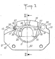
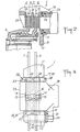
- the disc brake 1 shown in the accompanying drawing is a multi-disc brake, but could also be a single disc brake.
- This brake 1 comprises a first rotary disc 2 called exterior and a second rotary disc 3 said interior, both mounted on a hub 4 whose axis coincides with those of discs 2 and 3, the interior disc being further mounted on said hub 4 so as to be able to slide parallel to the axis thereof.
- Each brake disc 2 or 3 cooperates with a pair of friction pads 5 and 6 or 7 and 8 arranged on either side of the corresponding brake disc 2 or 3 and capable of being applied against the lateral faces of the latter.
- a fixed support 9 comprising a lateral flange 10 parallel to the brake discs 2,3 is provided with a central recess 11 and two transverse end arms 12,13, the lateral flange 10 being arranged parallel to and next to the internal disc 3
- the transverse arms 12, 13 are located at the upper ends of the flange 10 and extend parallel to the axis of the disks 2, 3 above a part of the periphery of the latter and in front and behind the friction pads 5.6 and 7.8.
- Each of these friction pads comprises a friction lining 14 and a lining carrier plate 15.
- the two lining carrier plates in principle juxtaposed with the inner shoe 6 of the outer disc 2 and the shoe outside 7 of inside disc 3, are made in a single piece so as to form only a single plate 16.
- transverse guide means for supporting the friction pads 5 to 8 and guiding their movement parallel to the axis of the brake discs 2,3.
- a caliper 19 is arranged between the two transverse arms 12, 13 over the brake discs 2,3 and their friction pads 5 to 8 so as to cover the disc-pad assembly and to be able to move through the central recess 11 of the fixed support 9 parallel to the axis of the brake discs 2,3.
- the stirrup 19 Seen in the direction of rotation of the disks 2, 3 corresponding to the forward direction, the stirrup 19 is mounted on the rear transverse arm 13 using a baluster 20 so as to be able to pivot around the axis of said column 20 parallel to the axis of the discs 2,3.
- the baluster 20 is fixed to a rear lug 21 of the stirrup 19 and slides in the bore of a bearing 22 incorporated in the rear arm 13.
- a motor control such as a hydraulic cylinder 23 whose movable part or piston 24 is capable of acting on the lining-carrier plate 15 of the inner shoe 8 and, by reaction and by means of its notched nose 25, on the lining plate 15 of the outer shoe 5.
- the central recess 11 is of dimensions such that, taking into account the configuration of the front and rear faces of the stirrup 19, the latter can pivot around the axis of the baluster 20 without it bumping against the internal face of said recess or against one of the bars 17, 18 of the trans arms verses 12, 13.
- the front and rear ends of the lining carrier plates 15 and 16 have, near their upper edge and opposite the guide bars 17 and 18, support and locking nozzles 26, 27 overhanging a retaining notch 28, 29 formed in the front or rear face of said plates 15, 16 and having a dihedral shape whose angle is acute, one of the faces of each retaining notch 28 or 29 coinciding with the lower face of the corresponding support spout 26 or 27.
- the retaining indentation 28 or 29 is opened to the corresponding front pin 17 and rear 18.
- Each guide and locking bar 17, 18 has the form of a dihedron whose edge is parallel to the axis of the brake discs 2 and 3 and of the baluster 20, whose angle is acute and whose face upper 30 or 31 is perpendicular to the radial median plane 32 of the brake 1.
- the retaining notches 28, 29 of the lining carrier plates 15, 16 have a dihedral shape corresponding to that of the dihedrons of the bars 17, 18 which, in the working and locking position (fig. 1), enter the corresponding retaining notches 28 or 29. As can be clearly seen in fig.
- the front end of the stirrup 19 has, for example on the outer side, that is to say of the nose 25, a locking notch 34 which, in the working position of the stirrup 19, is aligned with the notches retainer front 28 of the carrier plates 15.16.
- the locking notch 34 of the stirrup 19 has an active face which, in the working position of the stirrup 19, is parallel to the lower face of the front bar 17, aligned with the lower faces of the notches of front retainer 28 and which cooperates with the retainer key 33 in an area adjacent to the lining carrier plate 15, 16 of one of the friction pads 5 to 8.
- the locking notch 34 is advantageously provided on the side of the nose 25 of the stirrup 19 so that its active face cooperates with the outer end part of the key 33 in the region adjacent to the outer lining carrier plate 15.
- the locking notch 34 of the stirrup 19 also has the form of a dihedral whose angle is acute and identical to that of the front bar 17, of the fixed support 9.
- the key, retaining 33 protrudes on either side of the front arm 12 and is secured against any unwanted transverse movement relative to the lateral faces of said arm 12, using two pins 35 engaged in corresponding holes 36 of the key 33, these holes 36 being arranged in overhang relative to the lateral faces of the front arm 12.
- the end parts of the key 33 protrude on either side of the lateral faces of the front arm 12 and, in this case, it is the outer end of the key 33 which is used to lock the stirrup 19 in the working position.
- the locking notch 34 of the stirrup 19 is formed in a frontal protuberance 37 of the stirrup 19, this protrusion 37 being placed in front of and, seen in height, on either side of the edge of the dihedral of the front bar 17 when said stirrup is in the working position.
- the retaining key 33 has the form of a dihedron whose angle is identical to that of the dihedron of the front bar 17, the key perfectly matches the shape of said front bar and fully covers the front bar 1- 7 and constitutes the sliding and bearing surfaces for the front ends of the lining carrier plates 15, 16 and the stirrup 19, the protrusion 37 of which can rest, by the upper face of the locking notch 34 on l. 'upper wing of key 33.
- the upper face of the upper wing of the key 33 is in the same plane 38 perpendicular to the radial median plane 32 of the brake 1 as the upper face 31 of the rear bar 18 and the upper faces of the retaining notches 28,29 of the carrier plates 15,16 and of the locking notch 34 of the stirrup 19.
Landscapes
- Engineering & Computer Science (AREA)
- General Engineering & Computer Science (AREA)
- Mechanical Engineering (AREA)
- Braking Arrangements (AREA)
Applications Claiming Priority (2)
| Application Number | Priority Date | Filing Date | Title |
|---|---|---|---|
| FR8302212A FR2540952A1 (fr) | 1983-02-11 | 1983-02-11 | Frein a disque |
| FR8302212 | 1983-02-11 |
Publications (2)
| Publication Number | Publication Date |
|---|---|
| EP0117192A1 true EP0117192A1 (de) | 1984-08-29 |
| EP0117192B1 EP0117192B1 (de) | 1987-08-12 |
Family
ID=9285835
Family Applications (1)
| Application Number | Title | Priority Date | Filing Date |
|---|---|---|---|
| EP84400261A Expired EP0117192B1 (de) | 1983-02-11 | 1984-02-08 | Scheibenbremse |
Country Status (10)
| Country | Link |
|---|---|
| EP (1) | EP0117192B1 (de) |
| JP (1) | JPH0646057B2 (de) |
| AR (1) | AR231753A1 (de) |
| AU (1) | AU559053B2 (de) |
| BR (1) | BR8400648A (de) |
| DE (1) | DE3465370D1 (de) |
| ES (1) | ES285587Y (de) |
| FR (1) | FR2540952A1 (de) |
| IN (1) | IN160381B (de) |
| MX (1) | MX160307A (de) |
Cited By (4)
| Publication number | Priority date | Publication date | Assignee | Title |
|---|---|---|---|---|
| FR2590219A1 (fr) * | 1985-11-20 | 1987-05-22 | Bendix France | Dispositif de freinage electrique pour vehicule |
| FR2606105A1 (fr) * | 1986-10-29 | 1988-05-06 | Bendix France | Frein multidisques |
| FR2624232A1 (fr) * | 1987-12-04 | 1989-06-09 | Elf France | Dispositif de freinage d'un element rotatif |
| WO2014161679A1 (en) * | 2013-04-02 | 2014-10-09 | Haldex Brake Products Ab | Disc brake |
Families Citing this family (2)
| Publication number | Priority date | Publication date | Assignee | Title |
|---|---|---|---|---|
| JP4532299B2 (ja) * | 2005-01-28 | 2010-08-25 | 日立オートモティブシステムズ株式会社 | ディスクブレーキ |
| CN117329244B (zh) * | 2023-12-01 | 2024-02-02 | 山西强力矿用设备制造有限公司 | 液压湿式制动集成结构 |
Citations (6)
| Publication number | Priority date | Publication date | Assignee | Title |
|---|---|---|---|---|
| FR2221647A1 (de) * | 1973-03-17 | 1974-10-11 | Girling Ltd | |
| FR2272298A1 (de) * | 1974-05-20 | 1975-12-19 | Bendix Corp | |
| FR2342431A1 (fr) * | 1976-02-26 | 1977-09-23 | Girling Ltd | Frein a disque a etrier coulissant |
| GB2039646A (en) * | 1978-12-20 | 1980-08-13 | Tokico Ltd | Disc brake |
| EP0030184A1 (de) * | 1979-11-20 | 1981-06-10 | Societe Anonyme D.B.A. | Scheibenbremse |
| EP0036368A1 (de) * | 1980-03-18 | 1981-09-23 | Societe Anonyme D.B.A. | Scheibenbremse |
Family Cites Families (5)
| Publication number | Priority date | Publication date | Assignee | Title |
|---|---|---|---|---|
| FR2409423A1 (fr) * | 1977-11-17 | 1979-06-15 | Dba | Frein a disque et clavette de guidage pour un tel frein |
| DE2904118A1 (de) * | 1979-02-03 | 1980-09-04 | Teves Gmbh Alfred | Teilbelagscheibenbremse, insbesondere fuer kraftfahrzeuge |
| FR2529282A1 (fr) * | 1982-06-28 | 1983-12-30 | Dba | Element de coulissement et de verrouillage elastique pour frein a disque a etrier flottant supporte sur une colonnette axiale unique, et frein a disque equipe d'un tel element |
| FR2538487B1 (fr) * | 1982-12-23 | 1985-06-21 | Dba | Frein a disque |
| US4801625A (en) * | 1987-08-27 | 1989-01-31 | Akzo America Inc. | Bicyclic phosphate ether, ester, and carbonate intumescent flame retardant compositions |
-
1983
- 1983-02-11 FR FR8302212A patent/FR2540952A1/fr active Granted
-
1984
- 1984-01-17 IN IN46/DEL/84A patent/IN160381B/en unknown
- 1984-02-03 AU AU24072/84A patent/AU559053B2/en not_active Ceased
- 1984-02-03 MX MX20022684A patent/MX160307A/es unknown
- 1984-02-08 DE DE8484400261T patent/DE3465370D1/de not_active Expired
- 1984-02-08 EP EP84400261A patent/EP0117192B1/de not_active Expired
- 1984-02-10 ES ES1984285587U patent/ES285587Y/es not_active Expired
- 1984-02-10 AR AR29568684A patent/AR231753A1/es active
- 1984-02-10 BR BR8400648A patent/BR8400648A/pt not_active IP Right Cessation
- 1984-02-10 JP JP59022063A patent/JPH0646057B2/ja not_active Expired - Lifetime
Patent Citations (6)
| Publication number | Priority date | Publication date | Assignee | Title |
|---|---|---|---|---|
| FR2221647A1 (de) * | 1973-03-17 | 1974-10-11 | Girling Ltd | |
| FR2272298A1 (de) * | 1974-05-20 | 1975-12-19 | Bendix Corp | |
| FR2342431A1 (fr) * | 1976-02-26 | 1977-09-23 | Girling Ltd | Frein a disque a etrier coulissant |
| GB2039646A (en) * | 1978-12-20 | 1980-08-13 | Tokico Ltd | Disc brake |
| EP0030184A1 (de) * | 1979-11-20 | 1981-06-10 | Societe Anonyme D.B.A. | Scheibenbremse |
| EP0036368A1 (de) * | 1980-03-18 | 1981-09-23 | Societe Anonyme D.B.A. | Scheibenbremse |
Cited By (11)
| Publication number | Priority date | Publication date | Assignee | Title |
|---|---|---|---|---|
| FR2590219A1 (fr) * | 1985-11-20 | 1987-05-22 | Bendix France | Dispositif de freinage electrique pour vehicule |
| EP0223704A1 (de) * | 1985-11-20 | 1987-05-27 | BENDIX France Société Anonyme dite: | Elektrische Bremse für Fahrzeuge |
| US4784244A (en) * | 1985-11-20 | 1988-11-15 | Bendix France | Electrical braking device for vehicles |
| FR2606105A1 (fr) * | 1986-10-29 | 1988-05-06 | Bendix France | Frein multidisques |
| EP0266262A3 (en) * | 1986-10-29 | 1988-11-09 | Bendix France Societe Anonyme Dite: | Multi-disc brake |
| US4798268A (en) * | 1986-10-29 | 1989-01-17 | Bendix France | Multiple disc brake |
| FR2624232A1 (fr) * | 1987-12-04 | 1989-06-09 | Elf France | Dispositif de freinage d'un element rotatif |
| US5046590A (en) * | 1987-12-04 | 1991-09-10 | Elf France | Braking device for a rotary element |
| WO2014161679A1 (en) * | 2013-04-02 | 2014-10-09 | Haldex Brake Products Ab | Disc brake |
| US9863489B2 (en) | 2013-04-02 | 2018-01-09 | Haldex Brake Products Ab | Disc brake |
| EP2981729B1 (de) | 2013-04-02 | 2018-10-10 | Haldex Brake Products AB | Scheibenbremse |
Also Published As
| Publication number | Publication date |
|---|---|
| IN160381B (de) | 1987-07-11 |
| AU2407284A (en) | 1984-08-16 |
| JPS59151634A (ja) | 1984-08-30 |
| ES285587Y (es) | 1986-05-01 |
| MX160307A (es) | 1990-01-26 |
| FR2540952A1 (fr) | 1984-08-17 |
| EP0117192B1 (de) | 1987-08-12 |
| AR231753A1 (es) | 1985-02-28 |
| FR2540952B1 (de) | 1985-04-26 |
| AU559053B2 (en) | 1987-02-19 |
| DE3465370D1 (en) | 1987-09-17 |
| ES285587U (es) | 1985-10-01 |
| BR8400648A (pt) | 1984-09-18 |
| JPH0646057B2 (ja) | 1994-06-15 |
Similar Documents
| Publication | Publication Date | Title |
|---|---|---|
| EP1644604B1 (de) | Zunge zum verbinden zweier verkleidungen einer flugzeugstruktur | |
| FR2460420A1 (fr) | Frein a disque a garnitures partielles | |
| EP1164251A1 (de) | Schloss zur Sicherung von Laufschaufeln | |
| EP0402242B1 (de) | Spiegeleinheit für eine Sonnenblende, insbesondere in einem Fahrgastraum eines Kraftfahrzeuges | |
| EP0357469B1 (de) | Feder für Scheibenbremse | |
| EP0080949A1 (de) | Scheibenbremse und Bremsbacken für eine derartige Bremse | |
| EP0117192B1 (de) | Scheibenbremse | |
| EP0459867A1 (de) | Gelenkverbindung zwischen einem Scheibenwischerarm und einem Scheibenwischerblatt | |
| FR2722527A1 (fr) | Dispositif de verrouillage pour chassis a frappe | |
| FR2463875A1 (fr) | Dispositif de guidage a glissement pour l'etrier flottant d'un frein a disque | |
| EP0826574B1 (de) | Axial-Verriegelung | |
| FR2471793A1 (fr) | Dispositif de blocage d'une extremite d'une ceinture de securite pour vehicules automobiles, combine avec une glissiere d'un siege | |
| FR2567976A1 (fr) | Frein a disque a etrier coulissant partiellement pivotant | |
| EP0114549B1 (de) | Scheibenbremse | |
| WO1991006736A1 (fr) | Ensemble de roulement pour porte coulissante, notamment pour placard | |
| EP0115980B1 (de) | Scheibenbremse | |
| FR2939385A1 (fr) | Enemble de barres de toit pour vehicule automobile et vehicule automobile muni d'un tel ensemble. | |
| EP0928871B1 (de) | Verbesserung der gelenkigen Verbindung eines Flügels an einem Rahmen | |
| EP0118337A1 (de) | Scheibenbremse | |
| FR2771694A1 (fr) | Essuie-glace de vehicule automobile comportant des moyens de liaison directe entre un balai et un bras d'essuie-glace | |
| FR2803562A1 (fr) | Systeme de fixation d'un element rabattable de siege arriere sur un vehicule automobile | |
| FR2796014A1 (fr) | Mecanisme de blocage en rotation d'un plateau tournant sur un plateau fixe et siege de vehicule automobile muni d'un tel mecanisme | |
| FR2771147A1 (fr) | Frein a disque a etrier flottant a une seule colonnette | |
| FR2738590A1 (fr) | Verrou pour vitre coulissante | |
| FR2674148A1 (fr) | Cle avec panneton comportant un element mobile. |
Legal Events
| Date | Code | Title | Description |
|---|---|---|---|
| PUAI | Public reference made under article 153(3) epc to a published international application that has entered the european phase |
Free format text: ORIGINAL CODE: 0009012 |
|
| 17P | Request for examination filed |
Effective date: 19840216 |
|
| AK | Designated contracting states |
Designated state(s): DE GB IT NL SE |
|
| RAP1 | Party data changed (applicant data changed or rights of an application transferred) |
Owner name: BENDIX FRANCE |
|
| RAP1 | Party data changed (applicant data changed or rights of an application transferred) |
Owner name: BENDIX FRANCE |
|
| 17Q | First examination report despatched |
Effective date: 19860129 |
|
| D17Q | First examination report despatched (deleted) | ||
| ITF | It: translation for a ep patent filed | ||
| GRAA | (expected) grant |
Free format text: ORIGINAL CODE: 0009210 |
|
| AK | Designated contracting states |
Kind code of ref document: B1 Designated state(s): DE GB IT NL SE |
|
| PG25 | Lapsed in a contracting state [announced via postgrant information from national office to epo] |
Ref country code: NL Effective date: 19870812 |
|
| REF | Corresponds to: |
Ref document number: 3465370 Country of ref document: DE Date of ref document: 19870917 |
|
| NLV1 | Nl: lapsed or annulled due to failure to fulfill the requirements of art. 29p and 29m of the patents act | ||
| PLBE | No opposition filed within time limit |
Free format text: ORIGINAL CODE: 0009261 |
|
| STAA | Information on the status of an ep patent application or granted ep patent |
Free format text: STATUS: NO OPPOSITION FILED WITHIN TIME LIMIT |
|
| 26N | No opposition filed | ||
| ITTA | It: last paid annual fee | ||
| EAL | Se: european patent in force in sweden |
Ref document number: 84400261.8 |
|
| PGFP | Annual fee paid to national office [announced via postgrant information from national office to epo] |
Ref country code: DE Payment date: 19950209 Year of fee payment: 12 |
|
| PG25 | Lapsed in a contracting state [announced via postgrant information from national office to epo] |
Ref country code: DE Effective date: 19961101 |
|
| PGFP | Annual fee paid to national office [announced via postgrant information from national office to epo] |
Ref country code: GB Payment date: 19970130 Year of fee payment: 14 |
|
| PGFP | Annual fee paid to national office [announced via postgrant information from national office to epo] |
Ref country code: SE Payment date: 19970227 Year of fee payment: 14 |
|
| PG25 | Lapsed in a contracting state [announced via postgrant information from national office to epo] |
Ref country code: GB Free format text: LAPSE BECAUSE OF NON-PAYMENT OF DUE FEES Effective date: 19980208 |
|
| PG25 | Lapsed in a contracting state [announced via postgrant information from national office to epo] |
Ref country code: SE Free format text: LAPSE BECAUSE OF NON-PAYMENT OF DUE FEES Effective date: 19980209 |
|
| GBPC | Gb: european patent ceased through non-payment of renewal fee |
Effective date: 19980208 |
|
| EUG | Se: european patent has lapsed |
Ref document number: 84400261.8 |