EP0117596A1 - Verfahren zur Verringerung der Konvergenzzeit eines Echokompensators, sowie Vorrichtung zur Durchführung dieses Verfahrens - Google Patents
Verfahren zur Verringerung der Konvergenzzeit eines Echokompensators, sowie Vorrichtung zur Durchführung dieses Verfahrens Download PDFInfo
- Publication number
- EP0117596A1 EP0117596A1 EP84200257A EP84200257A EP0117596A1 EP 0117596 A1 EP0117596 A1 EP 0117596A1 EP 84200257 A EP84200257 A EP 84200257A EP 84200257 A EP84200257 A EP 84200257A EP 0117596 A1 EP0117596 A1 EP 0117596A1
- Authority
- EP
- European Patent Office
- Prior art keywords
- signal
- coefficients
- data
- transversal filter
- echo
- Prior art date
- Legal status (The legal status is an assumption and is not a legal conclusion. Google has not performed a legal analysis and makes no representation as to the accuracy of the status listed.)
- Granted
Links
- 238000000034 method Methods 0.000 title claims abstract description 35
- 230000005540 biological transmission Effects 0.000 claims abstract description 31
- 238000004364 calculation method Methods 0.000 claims abstract description 14
- 230000004044 response Effects 0.000 claims description 19
- 230000000737 periodic effect Effects 0.000 claims description 5
- 230000008569 process Effects 0.000 claims description 5
- 239000000654 additive Substances 0.000 claims description 2
- 230000000996 additive effect Effects 0.000 claims description 2
- 230000002457 bidirectional effect Effects 0.000 claims description 2
- 230000001360 synchronised effect Effects 0.000 claims 1
- 230000008878 coupling Effects 0.000 description 10
- 238000010168 coupling process Methods 0.000 description 10
- 238000005859 coupling reaction Methods 0.000 description 10
- 238000010586 diagram Methods 0.000 description 10
- 230000006870 function Effects 0.000 description 9
- 238000005070 sampling Methods 0.000 description 4
- 241000897276 Termes Species 0.000 description 3
- 238000010606 normalization Methods 0.000 description 3
- 230000003071 parasitic effect Effects 0.000 description 3
- 238000005311 autocorrelation function Methods 0.000 description 2
- 230000008859 change Effects 0.000 description 2
- 230000003111 delayed effect Effects 0.000 description 2
- 235000021183 entrée Nutrition 0.000 description 2
- 230000015572 biosynthetic process Effects 0.000 description 1
- 230000006872 improvement Effects 0.000 description 1
- 230000008054 signal transmission Effects 0.000 description 1
Images

Classifications
-
- H—ELECTRICITY
- H04—ELECTRIC COMMUNICATION TECHNIQUE
- H04B—TRANSMISSION
- H04B3/00—Line transmission systems
- H04B3/02—Details
- H04B3/20—Reducing echo effects or singing; Opening or closing transmitting path; Conditioning for transmission in one direction or the other
- H04B3/23—Reducing echo effects or singing; Opening or closing transmitting path; Conditioning for transmission in one direction or the other using a replica of transmitted signal in the time domain, e.g. echo cancellers
- H04B3/238—Reducing echo effects or singing; Opening or closing transmitting path; Conditioning for transmission in one direction or the other using a replica of transmitted signal in the time domain, e.g. echo cancellers using initial training sequence
Definitions
- the invention relates to a method for reducing the convergence time of an echo canceller connected in a transceiver equipment between two unidirectional channels transmitting and receiving coupled to a transmission channel bi ".
- this echo canceller comprising a transversal filter processing with N adjustable complex coefficients a complex signal deduced from the signal supplied to the transmission channel and arranged to supply a real signal component, this echo canceller also comprising a difference circuit for forming a difference signal between the signal in the reception channel and the output signal of the transversal filter.
- Echo cancellers are used for example in data transmission modems whose transmission and reception channels together forming a four-wire access are coupled by a coupling circuit, so that each modem has a two-wire access with the outside. .
- an echo signal which is a fraction of the signal transmitted by the channel. transmission from the same modem and which is due to imperfections in the coupling circuit and / or reflections in the link.
- the purpose of an echo canceller is to automatically cancel this echo signal, to allow simultaneous duplex transmission between two modems connected by their two-wire accesses.
- the coefficients of the transversal filter must be adjusted so that they are practically equal to samples of the impulse response of the echo path, so this filter then provides an echo copy signal which practically cancels the echo signal in the difference circuit output signal.
- the coefficients of the transversal filter are generally adjusted by successive recurrences, according to the gradient algorithm, so as to minimize the mean square value of the difference signal or error signal appearing at the output of the difference circuit.
- this method applied to the initialization of the coefficients before the transmission of the useful signal, provides a very long convergence time for the coefficients, amounting to several seconds and which may be unacceptable.
- the object of the present invention is to provide a method for initializing the complex coefficients of an echo canceller, also using the received signal directly, but allowing the calculation of the coefficients in a single step, in a minimum time which may be lower. than 4NT.
- the initial coefficients C of the transversal filter are set to zero, which also makes it possible, in the formula for calculating the coefficients, to substitute for the difference signal e R (n), the received signal e R (n) .
- the coefficients calculated as provided above are erroneous.
- a variant of the present invention provides a very simple method for correcting these calculated coefficients.
- the data of the training signal are transmitted in the direction of the transmission channel with a delay at least equal to a modulation period T relative to the data applied to the transversal filter
- the number N of the coefficients of the transversal filter is chosen at least one unit greater than the number corresponding to the maximum duration of the impulse response of the echo path
- the first calculated coefficient or one of the additional coefficients calculated is subtracted other coefficients calculated to form the desired coefficients of the cross filter.
- the present invention finally provides a simple method for generating a learning sequence meeting the two properties above.
- the data d (n) of the training signal are formed from two identical pseudo-random sequences of maximum length L, formed of elements + 1 and - 1 generated in synchronism at the frequency , these two sequences being shifted by a number K of periods TT relative to each other, the real and imaginary components of each datum d (n) at an instant nT being obtained respectively by additive and subtractive combination (or the reverse) of the values of the elements of the two sequences at the same time nT.
- the length L of the two said pseudo-random sequences is chosen so that L> 2N + 1 and the shift between these two sequences is chosen so that
- the convergence time of the echo canceller can be reduced to a value almost equal to 3NT.
- the modem provided with an echo canceller comprises a transmission channel 1 provided with a modulator 2 receiving baseband data to be transmitted and a reception channel 3 provided with a receiver 4 , responsible for restoring transmitted data from a remote modem.
- the output of modulator 2 is connected to the transmission access of the coupling circuit 5 and the reception access of this coupling circuit is connected, by means of a certain number of elements described below, to the input of the receiver 4.
- This circuit coupling 5 makes it possible to couple the two transmission and reception channels of the modem to the bidirectional transmission channel 6, for simultaneous duplex links with a remote modem not shown, coupled in the same way to the transmission channel 6.
- the modulator 2 transmits in the transmission channel 1 a signal modulated by the data to be transmitted to the remote modem, there may occur in the reception channel 3 an untimely echo signal coming from imperfections in the coupling circuit 5 or reflections in the transmission channel 6 and which can disturb in the receiver 4 the demodulation of the signal received from the remote modem.
- the echo canceller incorporated in the modem in FIG. 1 is responsible for eliminating the echo signal in reception channel 3.
- This echo canceller uses a complex data signal which is formed in modulator 2, from the baseband data to be transmitted and which allows the transmission by modulation of a carrier on a phase channel and a quadrature channel.
- the modulator 2 comprises a coding circuit 7 receiving the data to be transmitted and supplying a pair of signals representative of the amplitudes A (n) and of the phase changes ⁇ (n) to be assigned to the carrier in data function, at instants nT determined by the generator 8 of a clock signal at the frequency , being the modulation rate and n a variable integer from - ⁇ to + ⁇ .
- an adder circuit 9 is used, providing at each instant nT, the sum 'f (n) + ff which is representative of the absolute phase & (n ) of the modulated carrier to be transmitted.
- the two signals of amplitude A (n) and of phase ⁇ (n) together form a complex signal D (n) which is applied to circuit 10 which forms the real component A (n) .cos ⁇ (n) and the imaginary component A (n) .sin ⁇ (n).
- the complex signal D (n) is applied to a bandpass filter for complex signal formed by two bandpass filters 11 and 12 which receive respectively the real and imaginary components of the signal D (n) and whose bandwidth is centered on the frequency of the carrier used for transmission.
- the output signals of the two filters 11 and 12 are added in the adder circuit 13 to form the analog modulated carrier signal which is directed towards the transmission access of the coupling circuit 5.
- the complex signal D (n) thus formed in the modulator 2 is also used in the echo canceller.
- the echo canceller comprises a transverse filter 15 which receives the complex signal D (n) which is sampled at times nT and which is assumed to simplify the diagram, of analog type.
- the transverse filter 15 is provided with an adjustment circuit 16 for its complex coefficients. In the case of using the method of the present invention, the transverse filter 15 is arranged, as shown in FIG.
- the actual signal e R (n) supplied by the difference circuit 17 is applied to the adjustment circuit 16, in which it is used to adjust the coefficients of the transverse filter 15.
- the copy signal from echo ⁇ R (n) supplied by the transverse filter 15 is substantially equal to the echo signal appearing at the reception access of the coupling circuit 5 so that in the signal e R (n) supplied by the circuit 17, the signal echo is practically canceled.
- This difference signal thus freed from the echo signal is applied to the receiver 4, via the low-pass filter 20.
- the coefficients of the echo canceller are generally adjusted, in circuit 16, by successive recurrences, using the gradient algorithm, so as to minimize the mean square value of the signal d error provided by the difference circuit 17.
- learning D (n) having the property defined by formula (1) or by formula (la) when the echo signal has no continuous component.
- the present invention provides a method for calculating the coefficients also directly using the actual received signal, but with a shorter time for calculating the coefficients.
- the complex signal D (n) applied simultaneously to the filters 11 and 12, serving to produce the modulated carrier transmitted, and to the transverse filter 15 of the echo canceller is a learning signal periodic having a period LT at least equal to NT and meeting the two properties: for all i whole such that 1 ⁇ i ⁇ N - 1 for any integer i such that 0 ⁇ i ⁇ N - 1.
- the N coefficients of the transversal filter 15 are calculated in circuit 16, according to the expression:
- the terms used in this expression (6) have already been defined.
- the N initial coefficients represented by the vector C-3 are maintained throughout the duration of the calculation at the end of which the coefficients C are obtained.
- the received echo signal ⁇ R (n) is the real part of the complex signal e (n), which is written:
- Equation (7) can be written: E (n) and F (n) being matrices of order N, such as:
- said continuous component is not zero.
- the sampling frequency of the received signal is equal to , that is to say less than the Shannon frequency
- the continuous component of the impulse response of the echo path is obviously not zero.
- f e responding to Shannon's theorem
- e T we arrive at the same conclusion.
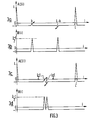
- the data transmitted from the learning signal D (n) is delayed by a modulation period T, using the delay circuit 21 shown in dotted lines in FIG. 1. relative to the data of signal D (n) supplied to the transverse filter of the echo canceller.
- This correction value x thus formed is subtracted from the other calculated coefficients, which, in accordance with formula (14), makes it possible to obtain the correct coefficients.
- the data sent by several periods T are delayed, it is possible to obtain, with an adapted number of coefficients N, several correction values x o , in principle identical.
- the device in FIG. 2 comprises two generators 25 and 26 of pseudo-random sequence maximum length. These two generators are identical and constituted in a well-known manner by a shift register with p elements, the outputs of two elements being applied to an exclusive OR circuit whose output is connected to the input of the register. Frequency pulses supplied by the generator 8 are used for shifting the registers of the two generators.
- the two binary signals a (n) and b (n) are applied to an encoder 28 which provides the desired complex training signal, formed from complex data d (n), having a real component d r (n) and a component imaginary of i (n).
- Table I shows the operations performed in the encoder 28. It is assumed to simplify the writing that the data supplied by the circuit 28 are normalized, that is to say that for these data the normalization coefficient ⁇ is equal to 1.
- the two generators 25 and 26 being supposed to supply binary signals a (n) and b (n) of value - 1 or 1, the first two columns show the 4 possible configurations for the pairs of signals a (n) and b (n ).
- AC (i) is the autocorrelation function of the complex signal d (n), for an offset i.
- the two functions AC (i) and B (i) are periodic with a period L.
- the autocorrelation function AC (i) takes, in a period L such as that defined for i going from 0 to L - 1, the following values: other values of i, i.e. 1 ⁇ i ⁇ L - 1, i + k, i ⁇ L - k.
- the function B (i) takes in a period, for i ranging from 0 to L - 1, the following values: for all other values of i, i.e.: 0 ⁇ i ⁇ L - 1, i ⁇ k and i + L - k.
- the learning signal d (n) formed as explained has these properties provided that: where k inf denotes the smaller of the two values k and L - k.
Landscapes
- Engineering & Computer Science (AREA)
- Computer Networks & Wireless Communication (AREA)
- Signal Processing (AREA)
- Cable Transmission Systems, Equalization Of Radio And Reduction Of Echo (AREA)
- Filters That Use Time-Delay Elements (AREA)
Applications Claiming Priority (2)
| Application Number | Priority Date | Filing Date | Title |
|---|---|---|---|
| FR8303113A FR2541837A1 (fr) | 1983-02-25 | 1983-02-25 | Procede de reduction du temps de convergence d'un annuleur d'echo et dispositif pour mettre en oeuvre ce procede |
| FR8303113 | 1983-02-25 |
Publications (2)
| Publication Number | Publication Date |
|---|---|
| EP0117596A1 true EP0117596A1 (de) | 1984-09-05 |
| EP0117596B1 EP0117596B1 (de) | 1988-09-07 |
Family
ID=9286265
Family Applications (1)
| Application Number | Title | Priority Date | Filing Date |
|---|---|---|---|
| EP84200257A Expired EP0117596B1 (de) | 1983-02-25 | 1984-02-22 | Verfahren zur Verringerung der Konvergenzzeit eines Echokompensators, sowie Vorrichtung zur Durchführung dieses Verfahrens |
Country Status (7)
| Country | Link |
|---|---|
| US (1) | US4571720A (de) |
| EP (1) | EP0117596B1 (de) |
| JP (1) | JPH0722252B2 (de) |
| AU (1) | AU562585B2 (de) |
| CA (1) | CA1211526A (de) |
| DE (1) | DE3473979D1 (de) |
| FR (1) | FR2541837A1 (de) |
Cited By (2)
| Publication number | Priority date | Publication date | Assignee | Title |
|---|---|---|---|---|
| EP0130263B1 (de) * | 1983-06-30 | 1988-06-01 | International Business Machines Corporation | Startverfahren für einen Echokompensationsfilter und dieses Verfahren anwendendes Nachrichtenübertragungssystem |
| EP0630119A3 (de) * | 1989-04-05 | 1995-03-08 | Codex Corp | Echokompensator. |
Families Citing this family (16)
| Publication number | Priority date | Publication date | Assignee | Title |
|---|---|---|---|---|
| US4705229A (en) | 1983-10-17 | 1987-11-10 | Mounque Barazone | Compact apparatus for laying paving fabric |
| FR2556530B1 (fr) * | 1983-10-28 | 1986-04-04 | Telediffusion Fse | Dispositif de correction d'echos, notamment pour systeme de diffusion de donnees |
| DE3583052D1 (de) * | 1984-03-30 | 1991-07-11 | Siemens Ag | Schaltungsanordnung zum pruefen der funktionsfaehigkeit einer datenuebertragunseinrichtung. |
| EP0167677B1 (de) * | 1984-07-13 | 1989-03-08 | BELL TELEPHONE MANUFACTURING COMPANY Naamloze Vennootschap | Anordnung zur Signalverarbeitung |
| JPH0773240B2 (ja) * | 1985-12-13 | 1995-08-02 | 日本電気株式会社 | 自動再トレ−ニング方式 |
| JPH0616592B2 (ja) * | 1985-12-23 | 1994-03-02 | 富士通株式会社 | Fdmモデム |
| US4703357A (en) * | 1985-12-24 | 1987-10-27 | Rca Corporation | Adaptive television deghosting system |
| US4698680A (en) * | 1985-12-24 | 1987-10-06 | Rca Corporation | Digital correlation apparatus as for a television deghosting system |
| BE905760A (fr) * | 1986-11-16 | 1987-05-18 | Electronique Et Telecomm Bell | Compensateur d'echo reglable. |
| CN1232048C (zh) * | 1994-05-06 | 2005-12-14 | 株式会社Ntt都科摩 | 回波消除器 |
| EP0708536B8 (de) * | 1994-05-07 | 2006-09-13 | Ntt Mobile Communications Network Inc. | Echokompensator und dessen lernverfahren |
| JP3097586B2 (ja) * | 1997-03-06 | 2000-10-10 | 日本電気株式会社 | 信号検出器 |
| US6317419B1 (en) * | 1998-06-10 | 2001-11-13 | Conexant Systems, Inc. | Method and apparatus for training an echo canceler in a PCM modem context |
| US6934387B1 (en) | 1999-12-17 | 2005-08-23 | Marvell International Ltd. | Method and apparatus for digital near-end echo/near-end crosstalk cancellation with adaptive correlation |
| US7006458B1 (en) | 2000-08-16 | 2006-02-28 | 3Com Corporation | Echo canceller disabler for modulated data signals |
| DE102004025576B4 (de) * | 2004-05-25 | 2006-03-30 | Infineon Technologies Ag | Sende-und Empfangsanordnung mit einer Regelung zur Störsignalunterdrückung |
Citations (3)
| Publication number | Priority date | Publication date | Assignee | Title |
|---|---|---|---|---|
| US4047013A (en) * | 1975-07-09 | 1977-09-06 | International Business Machines Corporation | Method and apparatus for fast determination of initial transversal equalizer coefficient values |
| EP0052362A1 (de) * | 1980-11-17 | 1982-05-26 | Nec Corporation | System für die schnelle Voreinstellung von Transversalentzerrern |
| EP0096936A1 (de) * | 1982-06-14 | 1983-12-28 | Telecommunications Radioelectriques Et Telephoniques T.R.T. | Verfahren zur Verkürzung der Konvergenzzeit eines Echokompensators sowie Vorrichtung zur Durchführung dieses Verfahrens |
Family Cites Families (6)
| Publication number | Priority date | Publication date | Assignee | Title |
|---|---|---|---|---|
| US4074086A (en) * | 1976-09-07 | 1978-02-14 | Bell Telephone Laboratories, Incorporated | Joint adaptive echo canceller and equalizer for two-wire full-duplex data transmission |
| FR2460075B1 (fr) * | 1979-06-22 | 1988-12-09 | Cit Alcatel | Annuleur d'echo adaptatif pour transmission de donnees en duplex |
| US4377793A (en) * | 1981-01-13 | 1983-03-22 | Communications Satellite Corporation | Digital adaptive finite impulse response filter with large number of coefficients |
| US4464545A (en) * | 1981-07-13 | 1984-08-07 | Bell Telephone Laboratories, Incorporated | Echo canceller |
| US4449231A (en) * | 1981-09-25 | 1984-05-15 | Northern Telecom Limited | Test signal generator for simulated speech |
| US4481622A (en) * | 1982-04-01 | 1984-11-06 | Anderson Jacobson, Inc. | High speed dial-up telephone circuit full duplex data transmission techniques |
-
1983
- 1983-02-25 FR FR8303113A patent/FR2541837A1/fr active Granted
-
1984
- 1984-02-22 DE DE8484200257T patent/DE3473979D1/de not_active Expired
- 1984-02-22 EP EP84200257A patent/EP0117596B1/de not_active Expired
- 1984-02-23 AU AU24886/84A patent/AU562585B2/en not_active Ceased
- 1984-02-23 CA CA000448082A patent/CA1211526A/en not_active Expired
- 1984-02-23 US US06/583,067 patent/US4571720A/en not_active Expired - Lifetime
- 1984-02-25 JP JP59033384A patent/JPH0722252B2/ja not_active Expired - Lifetime
Patent Citations (3)
| Publication number | Priority date | Publication date | Assignee | Title |
|---|---|---|---|---|
| US4047013A (en) * | 1975-07-09 | 1977-09-06 | International Business Machines Corporation | Method and apparatus for fast determination of initial transversal equalizer coefficient values |
| EP0052362A1 (de) * | 1980-11-17 | 1982-05-26 | Nec Corporation | System für die schnelle Voreinstellung von Transversalentzerrern |
| EP0096936A1 (de) * | 1982-06-14 | 1983-12-28 | Telecommunications Radioelectriques Et Telephoniques T.R.T. | Verfahren zur Verkürzung der Konvergenzzeit eines Echokompensators sowie Vorrichtung zur Durchführung dieses Verfahrens |
Non-Patent Citations (2)
| Title |
|---|
| FIFTH INTERNATIONAL CONFERENCE ON DIGITAL SATELLITE COMMUNICATIONS, Genoa, 23-26 mars 1981, pages 259-264, IEEE, US * |
| IBM TECHNICAL DISCLOSURE BULLETIN, vol. 21, no. 5, octobre 1978, pages 1916-1918, New York, US * |
Cited By (2)
| Publication number | Priority date | Publication date | Assignee | Title |
|---|---|---|---|---|
| EP0130263B1 (de) * | 1983-06-30 | 1988-06-01 | International Business Machines Corporation | Startverfahren für einen Echokompensationsfilter und dieses Verfahren anwendendes Nachrichtenübertragungssystem |
| EP0630119A3 (de) * | 1989-04-05 | 1995-03-08 | Codex Corp | Echokompensator. |
Also Published As
| Publication number | Publication date |
|---|---|
| JPH0722252B2 (ja) | 1995-03-08 |
| AU562585B2 (en) | 1987-06-11 |
| FR2541837A1 (fr) | 1984-08-31 |
| US4571720A (en) | 1986-02-18 |
| JPS59163924A (ja) | 1984-09-17 |
| EP0117596B1 (de) | 1988-09-07 |
| FR2541837B1 (de) | 1985-04-19 |
| CA1211526A (en) | 1986-09-16 |
| DE3473979D1 (en) | 1988-10-13 |
| AU2488684A (en) | 1984-08-30 |
Similar Documents
| Publication | Publication Date | Title |
|---|---|---|
| EP0117596B1 (de) | Verfahren zur Verringerung der Konvergenzzeit eines Echokompensators, sowie Vorrichtung zur Durchführung dieses Verfahrens | |
| EP0096936B1 (de) | Verfahren zur Verkürzung der Konvergenzzeit eines Echokompensators sowie Vorrichtung zur Durchführung dieses Verfahrens | |
| EP0116387B1 (de) | Verfahren zur Anfangseinstellung der Filterkoeffizienten in einer Anordnung zur Kompensation naher und ferner Echos, sowie Vorrichtung zur Durchführung dieses Verfahrens | |
| EP0113487B1 (de) | Verfahren zur Anwendung in einer Echounterdrückungseinrichtung zur Messung einer Echoverzögerung und Vorrichtung zur Durchführung des Verfahrens | |
| EP0107233B1 (de) | Basisbandsignal-Echoentzerrer | |
| EP0630119B1 (de) | Echokompensator | |
| FR2524742A1 (fr) | Procede de transmission de donnees en duplex sur un circuit telephonique commute et modem correspondant | |
| FR2623669A1 (fr) | Appareil et procede d'egalisation pour la transmission de donnees | |
| EP0107246A1 (de) | Empfänger für einen Datenübertragungsmodem, welcher einen Echokompensator und einen Entzerrer enthält | |
| EP0013343A1 (de) | Verfahren und Vorrichtung zur Auffindung einer Pseudo-Zufallsfolge von 0 Grad- und 180 Grad-Phasenänderungen der Trägerwelle in einem Datenempfänger | |
| FR2525054A1 (fr) | Emetteur concu pour l'emission de signaux modules en frequence | |
| EP0044598B1 (de) | Entzerrungsanordnung für ein zusammengesetztes Echosignal | |
| EP0146175B1 (de) | Schaltung zur Lokalisierung einer Signalreflexionsstelle auf einer Übertragungsleitung | |
| EP0036696A1 (de) | Echokompensator für ein Echosignal mit veränderlicher Phase | |
| EP0073869B1 (de) | Einrichtung zum Datenempfang mit einem hörerseitigen Echokompensator | |
| EP0081437A1 (de) | Echokompensatorsystem | |
| FR2480534A1 (fr) | Procede et dispositif d'annulation d'echo dans un systeme de transmission de donnees | |
| EP0174678A2 (de) | Echokompensator mit Anwendung der delta-Modulation | |
| EP0033568B1 (de) | Echokompensator mit vereinfachten Rechenschaltungen | |
| FR2546693A1 (fr) | Annuleur d'echo a filtre numerique adaptatif pour systeme de transmission | |
| EP0270706B1 (de) | Verfahren zum Vermindern der Konvergenzzeit eines Echokompensators | |
| FR2659811A1 (fr) | Recepteur de radionavigation par satellite. | |
| CA2196209C (fr) | Procede de compensation des differences en temps de propagation de groupe entre les filtres analogiques d'un emetteur et ceux d'un recepteur de signaux en quadrature de phase, dispositif de compensation et systeme de transmission correspondants | |
| CA1200940A (fr) | Annulateur d'echo pour transmission de donnees | |
| FR2568074A1 (fr) | Demodulateur de signaux electriques a plusieurs etats d'amplitude et de phase pour equipements de transmission de donnees. |
Legal Events
| Date | Code | Title | Description |
|---|---|---|---|
| PUAI | Public reference made under article 153(3) epc to a published international application that has entered the european phase |
Free format text: ORIGINAL CODE: 0009012 |
|
| AK | Designated contracting states |
Designated state(s): BE CH DE FR GB IT LI NL SE |
|
| 17P | Request for examination filed |
Effective date: 19841130 |
|
| 17Q | First examination report despatched |
Effective date: 19861208 |
|
| GRAA | (expected) grant |
Free format text: ORIGINAL CODE: 0009210 |
|
| AK | Designated contracting states |
Kind code of ref document: B1 Designated state(s): BE CH DE FR GB IT LI NL SE |
|
| PG25 | Lapsed in a contracting state [announced via postgrant information from national office to epo] |
Ref country code: NL Effective date: 19880907 |
|
| ITF | It: translation for a ep patent filed | ||
| REF | Corresponds to: |
Ref document number: 3473979 Country of ref document: DE Date of ref document: 19881013 |
|
| GBT | Gb: translation of ep patent filed (gb section 77(6)(a)/1977) | ||
| NLV1 | Nl: lapsed or annulled due to failure to fulfill the requirements of art. 29p and 29m of the patents act | ||
| PG25 | Lapsed in a contracting state [announced via postgrant information from national office to epo] |
Ref country code: LI Effective date: 19890228 Ref country code: CH Effective date: 19890228 Ref country code: BE Effective date: 19890228 |
|
| PLBE | No opposition filed within time limit |
Free format text: ORIGINAL CODE: 0009261 |
|
| STAA | Information on the status of an ep patent application or granted ep patent |
Free format text: STATUS: NO OPPOSITION FILED WITHIN TIME LIMIT |
|
| 26N | No opposition filed | ||
| BERE | Be: lapsed |
Owner name: TELECOMMUNICATIONS RADIOELECTRIQUES ET TELEPHONIQU Effective date: 19890228 |
|
| REG | Reference to a national code |
Ref country code: CH Ref legal event code: PL |
|
| REG | Reference to a national code |
Ref country code: FR Ref legal event code: TP |
|
| PGFP | Annual fee paid to national office [announced via postgrant information from national office to epo] |
Ref country code: SE Payment date: 19940222 Year of fee payment: 11 |
|
| ITTA | It: last paid annual fee | ||
| ITPR | It: changes in ownership of a european patent |
Owner name: CESSIONE;TRT TELECOMMUNICATIONS RADIOELECTRIQUES E |
|
| REG | Reference to a national code |
Ref country code: GB Ref legal event code: 732E |
|
| EAL | Se: european patent in force in sweden |
Ref document number: 84200257.8 |
|
| PG25 | Lapsed in a contracting state [announced via postgrant information from national office to epo] |
Ref country code: SE Effective date: 19950223 |
|
| EUG | Se: european patent has lapsed |
Ref document number: 84200257.8 |
|
| REG | Reference to a national code |
Ref country code: FR Ref legal event code: TP |
|
| REG | Reference to a national code |
Ref country code: GB Ref legal event code: 732E |
|
| PGFP | Annual fee paid to national office [announced via postgrant information from national office to epo] |
Ref country code: GB Payment date: 19970203 Year of fee payment: 14 |
|
| PGFP | Annual fee paid to national office [announced via postgrant information from national office to epo] |
Ref country code: FR Payment date: 19970218 Year of fee payment: 14 |
|
| PGFP | Annual fee paid to national office [announced via postgrant information from national office to epo] |
Ref country code: DE Payment date: 19970422 Year of fee payment: 14 |
|
| PG25 | Lapsed in a contracting state [announced via postgrant information from national office to epo] |
Ref country code: GB Free format text: LAPSE BECAUSE OF NON-PAYMENT OF DUE FEES Effective date: 19980222 |
|
| PG25 | Lapsed in a contracting state [announced via postgrant information from national office to epo] |
Ref country code: FR Free format text: THE PATENT HAS BEEN ANNULLED BY A DECISION OF A NATIONAL AUTHORITY Effective date: 19980228 |
|
| GBPC | Gb: european patent ceased through non-payment of renewal fee |
Effective date: 19980222 |
|
| PG25 | Lapsed in a contracting state [announced via postgrant information from national office to epo] |
Ref country code: DE Free format text: LAPSE BECAUSE OF NON-PAYMENT OF DUE FEES Effective date: 19981103 |
|
| REG | Reference to a national code |
Ref country code: FR Ref legal event code: ST |