EP0117652A2 - Vergnügungsmaschine - Google Patents
Vergnügungsmaschine Download PDFInfo
- Publication number
- EP0117652A2 EP0117652A2 EP84300588A EP84300588A EP0117652A2 EP 0117652 A2 EP0117652 A2 EP 0117652A2 EP 84300588 A EP84300588 A EP 84300588A EP 84300588 A EP84300588 A EP 84300588A EP 0117652 A2 EP0117652 A2 EP 0117652A2
- Authority
- EP
- European Patent Office
- Prior art keywords
- machine according
- display
- machine
- indicia
- display apparatus
- Prior art date
- Legal status (The legal status is an assumption and is not a legal conclusion. Google has not performed a legal analysis and makes no representation as to the accuracy of the status listed.)
- Withdrawn
Links
- 230000003993 interaction Effects 0.000 claims description 2
- 239000011159 matrix material Substances 0.000 claims description 2
- 230000000007 visual effect Effects 0.000 claims description 2
- 239000011521 glass Substances 0.000 abstract description 6
- 235000013399 edible fruits Nutrition 0.000 description 6
- 238000000034 method Methods 0.000 description 3
- 230000000694 effects Effects 0.000 description 2
- 238000005286 illumination Methods 0.000 description 2
- 238000003780 insertion Methods 0.000 description 2
- 230000037431 insertion Effects 0.000 description 2
- 230000003287 optical effect Effects 0.000 description 2
- 235000014676 Phragmites communis Nutrition 0.000 description 1
- 239000011093 chipboard Substances 0.000 description 1
- 239000005357 flat glass Substances 0.000 description 1
- 239000000463 material Substances 0.000 description 1
- 239000002184 metal Substances 0.000 description 1
- 239000011120 plywood Substances 0.000 description 1
Images
Classifications
-
- G—PHYSICS
- G07—CHECKING-DEVICES
- G07F—COIN-FREED OR LIKE APPARATUS
- G07F17/00—Coin-freed apparatus for hiring articles; Coin-freed facilities or services
- G07F17/32—Coin-freed apparatus for hiring articles; Coin-freed facilities or services for games, toys, sports, or amusements
- G07F17/3202—Hardware aspects of a gaming system, e.g. components, construction, architecture thereof
- G07F17/3204—Player-machine interfaces
- G07F17/3211—Display means
- G07F17/3213—Details of moving display elements, e.g. spinning reels, tumbling members
-
- A—HUMAN NECESSITIES
- A63—SPORTS; GAMES; AMUSEMENTS
- A63F—CARD, BOARD, OR ROULETTE GAMES; INDOOR GAMES USING SMALL MOVING PLAYING BODIES; VIDEO GAMES; GAMES NOT OTHERWISE PROVIDED FOR
- A63F7/00—Indoor games using small moving playing bodies, e.g. balls, discs or blocks
- A63F7/02—Indoor games using small moving playing bodies, e.g. balls, discs or blocks using falling playing bodies or playing bodies running on an inclined surface, e.g. pinball games
- A63F7/025—Pinball games, e.g. flipper games
- A63F7/027—Pinball games, e.g. flipper games electric
-
- A—HUMAN NECESSITIES
- A63—SPORTS; GAMES; AMUSEMENTS
- A63F—CARD, BOARD, OR ROULETTE GAMES; INDOOR GAMES USING SMALL MOVING PLAYING BODIES; VIDEO GAMES; GAMES NOT OTHERWISE PROVIDED FOR
- A63F7/00—Indoor games using small moving playing bodies, e.g. balls, discs or blocks
- A63F2007/0064—Ball games combined with other games
-
- A—HUMAN NECESSITIES
- A63—SPORTS; GAMES; AMUSEMENTS
- A63F—CARD, BOARD, OR ROULETTE GAMES; INDOOR GAMES USING SMALL MOVING PLAYING BODIES; VIDEO GAMES; GAMES NOT OTHERWISE PROVIDED FOR
- A63F3/00—Board games; Raffle games
- A63F3/06—Lottos or bingo games; Systems, apparatus or devices for checking such games
- A63F3/062—Bingo games, e.g. Bingo card games
Definitions
- This invention relates to an entertainment machine, or gaming machine, of the kind which can be operated, after actuation thereof by insertion of one or more coins or tokens into a coin mechanism of the machine, to play games in which combinations of indicia are randomly derived and displayed, a pay - out being made available to the player in the event that any such combination is of a predetermined winning nature.
- the indicia are displayed on the peripheries of reels mounted behind a window in a cabinet of the machine, selection of the indicia being effected by means of a mechanism or circuit which permits rotation of the reels for different random periods of time before they are brought to rest.
- An object of the present invention is to provide an entertainment machine of the kind described with which provision can be readily made for the abovementioned desirable features relating to player skill and to ready visibility of random indicia selection yet which presents an alternative format to that of the conventional fruit machine.
- an entertainment machine of the kind described having electrical display apparatus at an enclosed display area visibly exposed to the player at the front of the machine with different zones thereto on which in use randomly selected said indicia can be displayed, and a mechanism for effecting said random selection of said indicia, characterised in that said random selection mechanism comprises means for causing at least one object to move on a random basis across said enclosed display area towards a plurality of actuator devices, and means for effecting display of said indicia on said display apparatus in correspondence with interaction of the or each said object with said actuator devices.
- the machine whilst being of the gaming kind, presents an alternative format to that of the conventional fruit machine.
- the displayed win-determining indicia are selected as a consequence of the random movement of the or each said object across the said visibly-exposed area, it will be appreciated that the player can readily derive assurance as to the random nature of the selection process.
- provision can readily be made for the player to influence the random movement of the or each object as discussed in detail hereinafter.
- the display apparatus is arranged to present said different display zones in grid or matrix format and conveniently therefore the apparatus may comprise a screen in conjunction with a system operable to actuate selectively different zones of the screen.
- the apparatus may comprise an arrangement of lamps behind a translucent screen with circuitry operable to illuminate the lamps; or, alternatively an electronic vdu screen in conjunction with circuitry operable to generate displayed indicia thereon may be used.
- the arrangement may be such that predetermined indicia are associated respectively with the different zones, at least during the course of one game, and the random selection mechanism determines only which of the zones is to be actuated to effect display of the indicia thereat.
- the arrangement may be such that during the course of one game random selection can be made from a range of indicia for each zone.
- said object comprises a readily, freely movable object such as a disc or a ball and, in use, this is allowed to fall from an entry region at an upper part of the said area towards receptacles at a lower part thereof, the said actuator devices being provided respectively in or adjacent said receptacles and being operable to detect the presence of said object in contact therewith or in close proximity thereto.
- the said actuator devices may comprise electrical microswitches, reed switches, optical switches or any other suitable devices.
- Obstructions are preferably provided in the area between the entry region and the receptacles to deflect the falling object thereby to facilitate randomness in the manner in which the object reaches the receptacles.
- the obstructions may comprise pins in a board forming a back wall of the area through which the object falls.
- the receptacles may be associated respectively with different said zones or with different said indicia as desired. Multiple objects may be provided and these may be allowed to fall together or in succession. Alternatively there may be a single object (or a small number of objects) used repeatedly during a game.
- the player may influence the manner in which the or each object falls from the said entry region in terms of speed and/or angle and/or starting location.
- the object may comprise a ball which is impelled with a spring device up to the said entry region, the arrangement being such that the upward trajectory of the ball and consequently the parameters of its subsequent fall can be influenced by the manner in which the player operates the spring device.
- the said area of the random selection mechanism is preferably immediately adjacent or overlapping the said display apparatus.
- the said area is bounded at the front by a glass or similar transparent wall and is bounded at the rear by a wall which includes the said display apparatus whereby the display apparatus can be viewed through said front wall and the or each said object can move across the front of the display apparatus towards the said actuating devices.
- the machine may have a floor-standing cabinet generally like that of a conventional fruit machine.
- any suitable game may be played with the machine and, correspondingly win-assessment may be effected in any suitable manner.
- a "bingo" type game is played in that the display apparatus shows a grid of indicia, preferably numbers, and the random selection mechanism operates to select such indicia, which are then distinguished on the display apparatus for example by illumination thereof, a win indication being derived in the event that a line of distinguished indicia or other similar bingo-type combination is attained.
- provision may be made for changing the initially-displayed grid of indicia between games.
- the machine may also incorporate auxiliary features to improve the display and/or to extend the range of player controls.
- the machine may have an auxiliary display on which all selected indicia are recorded, this possibly being desirable in the abovementioned bingo context where indicia may be selected which are not present on the main display apparatus.
- provision may be made for permitting on a predetermined or random basis, adjustment of an attained display for example by interchanging displayed indicia.
- the player may be given the opportunity of a "double or nothing" or. similar gamble.
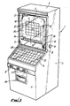
- the entertainment machine shown in the drawings is a "bingo" gaming machine and comprises a closed floor-standing cabinet 1 having side walls 2, a top wall 3, a lower front wall 4, a bottom wall and a back wall (both not visible in the drawings), and an upper front wall 5.
- the upper front wall 5 is set back relative to the lower front wall 4 and a rearwardly inclined intermediate front wall 6 extends between these. All walls are formed from veneered plywood or chipboard or similar rigid material except for the front walls 5, 6 which are formed wholly or largely from sheet glass.
- At appropriate positions on the cabinet 1 there are various player-operable controls such as press buttons 7, a coin slot 8 and a plunger control 9 yet to be described.
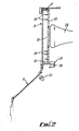
- the upper front wall 5 comprises a transparent glass sheet and behind this there is an opaque back board 25 (Figure 2) having a central rectangular display region 10 comprising a transparent glass sheet coplanar with the board 25. Behind this sheet 10 there is mounted an electronic visual display unit 26 (such as a cathode ray tube) so that the front screen of the vdu, which is approximately the same size and shape as the sheet 10, is clearly visible through the sheet 10.
- the vdu 26 is connected to an electronic control system (not shown) which is operable to cause the vdu screen to display a 5 x 5 grid 11 and numbers 12 in the spaces of the grid 11 (only some of which are shown).
- the back board 25 At the bottom of the back board 25 there is a horizontal row of upwardly open rearwardly inclined part-cylindrical receptacles 13 which communicate with holes 14 through the back board.
- the receptacles 13 At the rear of the back board the receptacles 13 have respective optical proximity detectors 27 each comprising a spaced light source and a light-sensitive electronic device arranged such that illumination of the device by the light source can be interrupted by the presence of an object at the back end of the pertaining receptacle thereby to cause the device to produce an electrical output.
- a spring-loaded plunger 15 at the bottom of a vertical channel 16 fixed to the front of the back board 25.
- the top of this channel 16 communicates with a top curved boundary structure 17 and there is a further boundary structure 18 at the opposite side.
- the receptacles 13 are in communication within the machine via a downwardly inclined passage 28 with an opening 19 immediately above the plunger 15 and a metal ball is provided which can freely pass along the receptacles 13 and from there via the said passage through the hole 19 to a position on top of the plunger 15.
- the plunger 15 is connected via a mechanical linkage to the aforesaid manual control 9 accessible externally of the machine.
- pins 20 are fixed into the board and project horizontally in front of same.
- the intermediate wall 6 comprises a translucent glass sheet divided by marked lines into a grid 22 of squares., and a different number 23 is marked within each square. Behind each square there is a respective lamp 21 ( Figure 2) which when operated acts to illuminate the pertaining marked number 23.
- the receptacles 13 relate respectively to different numbers which can be selected, for example, the numbers 1 to 50, and the same numbers are marked in succession in the grid 22. A random selection of 25 of these numbers is displayed in the grid 11 in random sequence.
- the aforesaid electronic control system within the machine which may be microprocessor-based, is capable of controlling all operations of the machine and is therefore connected via appropriate interface devices to all electrical components (such as the coin mechanism, the control button 7, the detectors 27, the lamps'21, the vdu 26 etc.).
- the ball In use, after actuation of the machine by insertion of one or more coins or tokens into the slot 8, the ball is delivered to the position at which it rests on top of the plunger 15. The player can now operate the plunger via the manual control 9 to cause the ball to be fired up the channel 16 to the top boundary structure 17 from where it then falls downwardly towards the receptacles 13. The pins 20 deflect the ball from side to side as it falls.
- the ball falls into one of the receptacles 13 and operates the pertaining actuating device 27.
- This causes the pertaining lamp 21 to be operated in the grid 22 and, if the corresponding number is also present in the grid 11, the number is appropriately distinguished in the grid 11, for example, by display of a line or cross through the number 12 on the screen of the vdu 26 or otherwise as desired.
- the ball then returns to its position on top of the plunger 15. The procedure can then be repeated a predetermined number of times before the game ends.
- the ball At the end of the game the ball is not returned but is held captive behind the back board 25 and the combination of numbers distinguished on the grid 11 is evaluated electronically by the control system.
- this combination is of a predetermined winning nature in that for example a line of numbers is illuminated, a pay-out mechanism within the machine is actuated and an appropriate number of coins or tokens is dispensed to the player through an outlet 24 in the front wall 4.
- the player can be assured of the randomness of such selection. Also, by appropriate manipulation of the manual control 9, the player can vary the movement of the plunger and hence the trajectory of the ball as it leaves the top of the channel 16 and thereby seek, by the exercise of skill, to influence the number selection process.
- the ball falls with an enclosed display area defined between the back board 25 and the clear glass sheet of the front wall 5.
- the screen of the vdu 26 forms a significant central part of the rear boundary of this area whereby the ball will tend to move downwardly across and in front of the screen especially in so far as the ball will tend to drop at the end of its trajectory or after bouncing off a pin near the boundary 18 at a location generally directly above the centre of the vdu screen. This gives a particularly appealing effect in that the vdu display and the randomly falling ball become intimately associated in the mind of the player.
- the machine in like manner to a conventional fruit machine is contained within a floor-standing cabinet and dispenses coins or tokens when a win is obtained, yet the machine is otherwise different from and therefore presents to the player an alternative to such conventional machine.
- the machine may incorporate further auxiliary features as desired such as one or both of the following:
- the electronically controlled vdu 26 advantageously permits convenient use of an adjustment control as mentioned above, and also there is the possibility of changing the fixed numbers on the top screen between games on an automatic or player-initiated basis as desired.
- the grid 22 may be replaced with a vdu display in like manner to the vdu 26. If desired it is even possible to use a back illuminated translucent grid (like the grid 22) in place of the vdu 26, although this may be less advantageous.
- the invention is not intended to be restricted to a bingo type game but may be applied to other games involving the random selection of indicia to be displayed to the player such as roulette even dominoes, or other games.
Landscapes
- Engineering & Computer Science (AREA)
- Multimedia (AREA)
- Physics & Mathematics (AREA)
- General Physics & Mathematics (AREA)
- Pinball Game Machines (AREA)
- Adjustment And Processing Of Grains (AREA)
- Toys (AREA)
Applications Claiming Priority (2)
| Application Number | Priority Date | Filing Date | Title |
|---|---|---|---|
| GB8302716 | 1983-02-01 | ||
| GB838302716A GB8302716D0 (en) | 1983-02-01 | 1983-02-01 | Entertainment machine |
Publications (2)
| Publication Number | Publication Date |
|---|---|
| EP0117652A2 true EP0117652A2 (de) | 1984-09-05 |
| EP0117652A3 EP0117652A3 (en) | 1985-08-28 |
Family
ID=10537282
Family Applications (1)
| Application Number | Title | Priority Date | Filing Date |
|---|---|---|---|
| EP84300588A Withdrawn EP0117652A3 (en) | 1983-02-01 | 1984-01-31 | Entertainment machine |
Country Status (3)
| Country | Link |
|---|---|
| EP (1) | EP0117652A3 (de) |
| ES (1) | ES8500670A1 (de) |
| GB (1) | GB8302716D0 (de) |
Cited By (1)
| Publication number | Priority date | Publication date | Assignee | Title |
|---|---|---|---|---|
| ES2072187A2 (es) * | 1993-03-23 | 1995-07-01 | Gespamar Sl | Mejoras introducidas en maquinas recreativas con premios en metalico. |
Family Cites Families (3)
| Publication number | Priority date | Publication date | Assignee | Title |
|---|---|---|---|---|
| DE1114350B (de) * | 1959-05-21 | 1961-09-28 | Guenter Wulff | Einen Gewinn in Aussicht stellendes Muenz-Spielgeraet |
| US4017077A (en) * | 1975-07-03 | 1977-04-12 | Bally Manufacturing Corporation | Matrix transformation pin ball machine with score multiplier option |
| GB2086115B (en) * | 1980-10-21 | 1984-07-18 | Ace Coin Equip | A coin operated amusement or gaming machine |
-
1983
- 1983-02-01 GB GB838302716A patent/GB8302716D0/en active Pending
-
1984
- 1984-01-31 EP EP84300588A patent/EP0117652A3/en not_active Withdrawn
- 1984-02-01 ES ES529390A patent/ES8500670A1/es not_active Expired
Cited By (1)
| Publication number | Priority date | Publication date | Assignee | Title |
|---|---|---|---|---|
| ES2072187A2 (es) * | 1993-03-23 | 1995-07-01 | Gespamar Sl | Mejoras introducidas en maquinas recreativas con premios en metalico. |
Also Published As
| Publication number | Publication date |
|---|---|
| ES529390A0 (es) | 1984-11-01 |
| GB8302716D0 (en) | 1983-03-02 |
| ES8500670A1 (es) | 1984-11-01 |
| EP0117652A3 (en) | 1985-08-28 |
Similar Documents
| Publication | Publication Date | Title |
|---|---|---|
| CA1261970A (en) | Amusement arcade machines for use in amusement and/or gaming or the like | |
| US5016879A (en) | Pachinko game | |
| AU758255B2 (en) | Gaming machine | |
| EP0971326B1 (de) | Unterhaltungsgeräte | |
| US6619659B2 (en) | Drop slot game machine | |
| US5697611A (en) | Redemption-type arcade game with game token return | |
| EP0219305A2 (de) | Unterhaltungsapparate | |
| EP0060019A1 (de) | Unterhaltungsapparate | |
| GB2097160A (en) | Entertainment machines | |
| JPH09122294A (ja) | 遊技機 | |
| GB2349494A (en) | Entertainment machine with supplementary play feature | |
| GB2133994A (en) | Game apparatus | |
| JPH0355081A (ja) | 遊技機 | |
| EP0117652A2 (de) | Vergnügungsmaschine | |
| EP0233298B1 (de) | Zum Vergnügen und/oder zum Spielen oder dergleichen verwendete Spielhallenautomaten | |
| EP0862152A1 (de) | Unterhaltungsautomaten | |
| GB2248403A (en) | Entertainment machines | |
| JPS6028474Y2 (ja) | スロツトマシン | |
| ES2011872A6 (es) | Perfeccionamientos en maquinas de juego recreativo. | |
| GB2367939A (en) | Games machine with matrix second game | |
| JPH09103541A (ja) | コイン式弾球遊技機及び遊技システム | |
| GB2395666A (en) | Grabber and coin pusher machine | |
| JPH0347284A (ja) | パチンコ式組合せゲーム機 | |
| JP3402306B2 (ja) | 遊技機 | |
| JPH042382A (ja) | パチンコ機 |
Legal Events
| Date | Code | Title | Description |
|---|---|---|---|
| PUAI | Public reference made under article 153(3) epc to a published international application that has entered the european phase |
Free format text: ORIGINAL CODE: 0009012 |
|
| AK | Designated contracting states |
Designated state(s): AT BE CH DE FR IT LI LU NL SE |
|
| PUAL | Search report despatched |
Free format text: ORIGINAL CODE: 0009013 |
|
| AK | Designated contracting states |
Designated state(s): AT BE CH DE FR IT LI LU NL SE |
|
| STAA | Information on the status of an ep patent application or granted ep patent |
Free format text: STATUS: THE APPLICATION HAS BEEN WITHDRAWN |
|
| 18W | Application withdrawn |
Withdrawal date: 19850925 |
|
| RIN1 | Information on inventor provided before grant (corrected) |
Inventor name: DENTON, JOHN BARRY |