EP0117877A1 - Organe de transmission de vibrations - Google Patents
Organe de transmission de vibrations Download PDFInfo
- Publication number
- EP0117877A1 EP0117877A1 EP83101698A EP83101698A EP0117877A1 EP 0117877 A1 EP0117877 A1 EP 0117877A1 EP 83101698 A EP83101698 A EP 83101698A EP 83101698 A EP83101698 A EP 83101698A EP 0117877 A1 EP0117877 A1 EP 0117877A1
- Authority
- EP
- European Patent Office
- Prior art keywords
- layer
- element according
- support beam
- outside
- perforated
- Prior art date
- Legal status (The legal status is an assumption and is not a legal conclusion. Google has not performed a legal analysis and makes no representation as to the accuracy of the status listed.)
- Granted
Links
- 230000005540 biological transmission Effects 0.000 title claims description 4
- 239000000463 material Substances 0.000 claims abstract description 34
- 229920001971 elastomer Polymers 0.000 claims abstract description 14
- 238000005452 bending Methods 0.000 claims abstract 2
- 239000004567 concrete Substances 0.000 claims description 12
- 239000000806 elastomer Substances 0.000 claims description 12
- 230000000694 effects Effects 0.000 claims description 10
- 229920003023 plastic Polymers 0.000 claims description 9
- 239000004033 plastic Substances 0.000 claims description 9
- 238000013016 damping Methods 0.000 claims description 8
- 238000004519 manufacturing process Methods 0.000 claims description 6
- 238000000465 moulding Methods 0.000 claims description 6
- 238000000926 separation method Methods 0.000 claims description 5
- 239000002184 metal Substances 0.000 claims description 4
- 229910052751 metal Inorganic materials 0.000 claims description 4
- 230000006835 compression Effects 0.000 claims description 3
- 238000007906 compression Methods 0.000 claims description 3
- 229920003051 synthetic elastomer Polymers 0.000 claims description 3
- 239000005061 synthetic rubber Substances 0.000 claims description 3
- 229920003052 natural elastomer Polymers 0.000 claims description 2
- 229920001194 natural rubber Polymers 0.000 claims description 2
- 230000005855 radiation Effects 0.000 claims description 2
- 244000043261 Hevea brasiliensis Species 0.000 claims 1
- 239000011230 binding agent Substances 0.000 claims 1
- JEIPFZHSYJVQDO-UHFFFAOYSA-N iron(III) oxide Inorganic materials O=[Fe]O[Fe]=O JEIPFZHSYJVQDO-UHFFFAOYSA-N 0.000 claims 1
- 239000011159 matrix material Substances 0.000 claims 1
- 239000005060 rubber Substances 0.000 abstract description 2
- 238000003825 pressing Methods 0.000 description 7
- 229910000831 Steel Inorganic materials 0.000 description 6
- 238000010276 construction Methods 0.000 description 6
- 238000000034 method Methods 0.000 description 6
- 239000010959 steel Substances 0.000 description 6
- 239000000725 suspension Substances 0.000 description 3
- 238000005056 compaction Methods 0.000 description 2
- 238000013461 design Methods 0.000 description 2
- 238000012545 processing Methods 0.000 description 2
- 238000007789 sealing Methods 0.000 description 2
- SZUVGFMDDVSKSI-WIFOCOSTSA-N (1s,2s,3s,5r)-1-(carboxymethyl)-3,5-bis[(4-phenoxyphenyl)methyl-propylcarbamoyl]cyclopentane-1,2-dicarboxylic acid Chemical compound O=C([C@@H]1[C@@H]([C@](CC(O)=O)([C@H](C(=O)N(CCC)CC=2C=CC(OC=3C=CC=CC=3)=CC=2)C1)C(O)=O)C(O)=O)N(CCC)CC(C=C1)=CC=C1OC1=CC=CC=C1 SZUVGFMDDVSKSI-WIFOCOSTSA-N 0.000 description 1
- 229910001018 Cast iron Inorganic materials 0.000 description 1
- VEXZGXHMUGYJMC-UHFFFAOYSA-M Chloride anion Chemical compound [Cl-] VEXZGXHMUGYJMC-UHFFFAOYSA-M 0.000 description 1
- 229910001208 Crucible steel Inorganic materials 0.000 description 1
- 229920000459 Nitrile rubber Polymers 0.000 description 1
- -1 Polyethylene Polymers 0.000 description 1
- 239000004698 Polyethylene Substances 0.000 description 1
- 230000015572 biosynthetic process Effects 0.000 description 1
- 238000005266 casting Methods 0.000 description 1
- 230000001413 cellular effect Effects 0.000 description 1
- 239000004568 cement Substances 0.000 description 1
- 239000002131 composite material Substances 0.000 description 1
- 229940126543 compound 14 Drugs 0.000 description 1
- 239000000470 constituent Substances 0.000 description 1
- 230000002349 favourable effect Effects 0.000 description 1
- 239000000945 filler Substances 0.000 description 1
- 238000009776 industrial production Methods 0.000 description 1
- 239000000203 mixture Substances 0.000 description 1
- 238000012986 modification Methods 0.000 description 1
- 230000004048 modification Effects 0.000 description 1
- 238000012856 packing Methods 0.000 description 1
- 229920000573 polyethylene Polymers 0.000 description 1
- 229920002635 polyurethane Polymers 0.000 description 1
- 239000004814 polyurethane Substances 0.000 description 1
- 230000003014 reinforcing effect Effects 0.000 description 1
- 239000007787 solid Substances 0.000 description 1
- 238000003466 welding Methods 0.000 description 1
Images

Classifications
-
- B—PERFORMING OPERATIONS; TRANSPORTING
- B28—WORKING CEMENT, CLAY, OR STONE
- B28B—SHAPING CLAY OR OTHER CERAMIC COMPOSITIONS; SHAPING SLAG; SHAPING MIXTURES CONTAINING CEMENTITIOUS MATERIAL, e.g. PLASTER
- B28B1/00—Producing shaped prefabricated articles from the material
- B28B1/08—Producing shaped prefabricated articles from the material by vibrating or jolting
-
- B—PERFORMING OPERATIONS; TRANSPORTING
- B06—GENERATING OR TRANSMITTING MECHANICAL VIBRATIONS IN GENERAL
- B06B—METHODS OR APPARATUS FOR GENERATING OR TRANSMITTING MECHANICAL VIBRATIONS OF INFRASONIC, SONIC, OR ULTRASONIC FREQUENCY, e.g. FOR PERFORMING MECHANICAL WORK IN GENERAL
- B06B3/00—Methods or apparatus specially adapted for transmitting mechanical vibrations of infrasonic, sonic, or ultrasonic frequency
-
- B—PERFORMING OPERATIONS; TRANSPORTING
- B28—WORKING CEMENT, CLAY, OR STONE
- B28B—SHAPING CLAY OR OTHER CERAMIC COMPOSITIONS; SHAPING SLAG; SHAPING MIXTURES CONTAINING CEMENTITIOUS MATERIAL, e.g. PLASTER
- B28B1/00—Producing shaped prefabricated articles from the material
- B28B1/08—Producing shaped prefabricated articles from the material by vibrating or jolting
- B28B1/081—Vibration-absorbing means
-
- B—PERFORMING OPERATIONS; TRANSPORTING
- B28—WORKING CEMENT, CLAY, OR STONE
- B28B—SHAPING CLAY OR OTHER CERAMIC COMPOSITIONS; SHAPING SLAG; SHAPING MIXTURES CONTAINING CEMENTITIOUS MATERIAL, e.g. PLASTER
- B28B7/00—Moulds; Cores; Mandrels
- B28B7/36—Linings or coatings, e.g. removable, absorbent linings, permanent anti-stick coatings; Linings becoming a non-permanent layer of the moulded article
Definitions
- the present invention relates to an element for transmitting vibrations in a vibrating or vibrating device.
- Said element is said to be used in the industrial production of all types of concrete and cement products, in particular slabs, and in the rational production of molded articles from other materials in a wide range of technical activities, such as filling, distributing, dosing and compacting processes on vibrations. or vibrating devices can be used.
- FIGS. 1 a and 1 b The basic construction according to FIGS. 1 a and 1 b is operated according to the so-called push-through method and the other basic construction according to FIGS. 2 a and 2 b according to the so-called hermetic method.
- La and 2a show the devices after Filling the mold cavity with the filling material and
- FIGS. 1b and 2b show the devices when demolding the filling material compressed into a plate.
- the construction according to FIG. 1 has a mold base 1, which normally consists of a solid steel plate, which, according to FIG. Rods 4 connected to a lifting device, not shown, extend freely through the vibrating table 2 and engage the mold base 1 in order to bring it to the desired height with respect to the mold frame.
- a vibrating device 5 engages with the underside of the vibrating table 2 in order to generate the desired vibrations, which are then transmitted via the vibrating table 2 to the mold base 1 and thus to the filling material 6.
- On the mold base 1 there is usually a structured plastic mat 7 on its surface facing the filling material.
- concrete is filled as filling material 6 into the mold cavity according to FIG.
- Very thin components can be produced in relation to the edge length, since the finished molding is ejected lying on the mold base.
- Vibrations generated for concrete compaction are transferred directly into the material, without hindrance or damping by the mass of any machine parts, such as mold frames, which are loaded on the vibration table.
- the vibrating table 2 has a vibrating table 2, which at the same time forms the mold base.
- the vibrating table 2 is covered with a plastic mat 7, which is structured on its upper side and has a raised edge.
- a molding frame 3 lies sealingly on the upstanding border, which forms the molding cavity with the mat for receiving the filling material 6.
- the vibrating table or mold base is set in vibration directly by means of a vibrating device (not shown), with a press again exerting the desired pressing pressure on the entire filling material, as in the device according to FIG. 2b, the mold frame 3 is lifted off the mold base 2 or the plastic mat 7 according to FIG. 2b, the compacted component remaining clamped in the frame 3 when it is lifted off.
- the device generates relatively little noise, since there is no steel plate lying freely in the mold, which is caused to vibrate by vibrating forces.
- the rubber or plastic layers on the vibrating table are relatively dimensionally stable, i.e. they tend less to flow and / or creep due to the edge clamping by the mold frame.
- the aim of the present invention is to provide an element for transmitting vibrations in a vibrating or vibrating device for processing a wide variety of materials, which has a low noise emission and which, when used as a molded floor or vibrating table for the production of, in particular, plate-like concrete elements, creates a vibrating or vibrating device, which allows the use of the above-mentioned advantages of the two basic constructions according to FIGS. 1 and 2.
- the plate-like element according to FIG. 3 has a rigid or dimensionally stable support structure 10, which can be constructed in a rust-like manner and can be used as a molded floor or vibrating table.
- the supporting structure 10 On its underside, the supporting structure 10 is non-positively and interchangeably connected to a wear-resistant plate 11, e.g. screwed.
- the support structure 10 On its upper side, the support structure 10 is non-positively connected to a perforated sheet 12, e.g. connected by welding.
- the sheet 12 has circular, through-holes 13 for the purpose of reducing the noise, the hole proportion being at least 20% of the sheet area.
- the unit formed from the support structure 10 and perforated plate 12 is covered on all sides with the exception of the underside with a rubber-elastic and / or vibration-damping mass 14, which also fills the cutouts in the interior of the support structure 10, and is intimately connected.
- All elastomers including cellular or porous) based on natural or synthetic rubber, synthetic rubber and / or plastics (with or without filler or reinforcing constituents) with viscoelastic properties are suitable as mass 14, with the suspension and in other cases in certain cases Cases where the damping properties are in the foreground.
- the mass 14 is preferably applied in the casting process. As mass 14 comes e.g. Polyethylene, cast polyurethane, polyvinil chloride, nitrile rubber or polychlorobutadiene in question.
- the covering mass 14 has a high sound-reducing effect and offers the possibility of a layer 15 and a layer lying above the perforated plate 12 form lateral border 16 of the mold base, both of which can be created in such a way that they meet the respective application.
- the unit formed from the elastomer layer 15, the perforated plate 12 and the support structure 10 can be regarded as a three-layer body, the sound radiation in particular if the layer thickness ratios (layer thickness of the elastomer layer 15, the perforated plate layer 13 and the support structure 10) and the proportion of holes in the perforated plate are selected appropriately is reduced through the three layers without impairing the transmission of vibrations.
- the element according to FIG. 3 is particularly suitable for use as a molded floor or vibrating table for the production of concrete elements, such as concrete slabs, in a concrete press roughly corresponding to those according to FIGS. 1 and 2.
- the element according to FIG. 3 replaces the steel plate 1 together with it Mat 7 resp. the vibrating table 2 together with the plastic mat 7.
- the vibrating device in the example according to FIG. 1 continues to act on the vibrating table 2 and in the example according to FIG. 2 now on the underside of the wear plate 11, and in both examples the frame 3 acts with the latter Side border 16 designed appropriately for the purpose.
- the lateral border 16 can be designed as a seal between the mold base and the mold frame 3 when internal pressure occurs, originating from the pressing force acting on the filling material from above, in the sense of a lip sleeve or sealing packing, as shown in FIGS. 4a to 4c.
- the upper side of the top layer 15 made of elastomer, which is in direct contact with the filling material to be processed into a shaped piece, is in front preferably structured to give the piece to be manufactured the desired surface structure.
- the elastomer layer 15 and the perforated plate 12 act in a highly advantageous manner. -particularly together, after the pressing process, the separation effect between the top of the mold base and the compressed or compacted molding, for example made of concrete.
- the elastomer layer 15 lying above the perforated plate 12 should have good suspension properties.
- the deflection of the elastomer layer 15 is greater at the points above the holes 13 of the perforated plate 12 than above the points where the plate 12 is not perforated and thus the elastomer layer 15 is supported.
- the elastomer layer 15 also springs back to its initial position to different extents in accordance with the previous different deflections.
- the molded part compressed or compressed from the filling material e.g. a concrete slab, partly from the elastomer layer, which supports the separation effect.
- the holes 13 of the layer formed by the perforated plate 12 can be completely filled with air or another gas or with the plastic compound 14.
- the layer thickness ratios of elastomer layer 15 and perforated plate 12 can be matched to the respective filling material / pressed material and to the pressing pressures to be maintained.
- the composition of the material to be pressed must also be taken into account. This example, coarse-grained, as with rather thick layers 12 and 15 and with coarse-per-f or Arthurm perforated plate, an optimal separating effect can be brought about.
- masses 14 of different properties can be used at the different locations of the element according to FIG. 3.
- S o it may be desirable that, when the top layer should be 15 mass forming the suspension properties and in which the interior of the supporting structure 10 chwingungsdämpfungseigenschaften filling mass S in the foreground.
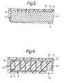
- a plate-shaped, rigid or dimensionally stable cast body 17 made of cast iron or cast steel could also be used, as shown in FIG. 5, the outer layer 18 of which has an outer layer, e.g. circular recesses 13 is provided, which outer layer 18 takes over the function of the perforated plate 12 with a corresponding proportion of holes.
- such a cast body which can also be provided with recesses on the inside or on its underside, is encased and intimately connected with a mass 14, so that an upper layer located above the grid-like recesses in the outer layer and one Border is formed from the mass 14.
- the underside of the support structure 10 is also provided with a perforated sheet 12 non-positively, for example by means of a welded connection, and covered with a layer 15 of the mass 14 and intimately connected.
- Both the lower perforated plate 12 and the layer 15 can be excluded in an area 18 which can be configured in a suitable manner in order to come into engagement with a vibrating device.
- the element according to FIG. 5 could also have recesses 13 in the lower outer layer of the cast body 17 and a further layer from the mass 14 covering this outer layer and thereby be formed on the underside in accordance with the element according to FIGS. -6.
- the perforated plate 12 is preferably made of metal, such as steel. However, it can also be made of a suitable plastic, which in the present context has the same or a similar effect as a metal and is therefore also suitable as a material for the perforated plate 12.
Landscapes
- Engineering & Computer Science (AREA)
- Mechanical Engineering (AREA)
- Manufacturing & Machinery (AREA)
- Chemical & Material Sciences (AREA)
- Ceramic Engineering (AREA)
- Floor Finish (AREA)
- Springs (AREA)
- Vibration Prevention Devices (AREA)
- Pulleys (AREA)
- Gear-Shifting Mechanisms (AREA)
- Ultra Sonic Daignosis Equipment (AREA)
Priority Applications (3)
| Application Number | Priority Date | Filing Date | Title |
|---|---|---|---|
| AT83101698T ATE19485T1 (de) | 1983-02-22 | 1983-02-22 | Element zur uebertragung von vibrationen. |
| EP83101698A EP0117877B1 (fr) | 1983-02-22 | 1983-02-22 | Organe de transmission de vibrations |
| DE8383101698T DE3363246D1 (en) | 1983-02-22 | 1983-02-22 | Vibration transmission member |
Applications Claiming Priority (1)
| Application Number | Priority Date | Filing Date | Title |
|---|---|---|---|
| EP83101698A EP0117877B1 (fr) | 1983-02-22 | 1983-02-22 | Organe de transmission de vibrations |
Publications (2)
| Publication Number | Publication Date |
|---|---|
| EP0117877A1 true EP0117877A1 (fr) | 1984-09-12 |
| EP0117877B1 EP0117877B1 (fr) | 1986-04-30 |
Family
ID=8190308
Family Applications (1)
| Application Number | Title | Priority Date | Filing Date |
|---|---|---|---|
| EP83101698A Expired EP0117877B1 (fr) | 1983-02-22 | 1983-02-22 | Organe de transmission de vibrations |
Country Status (3)
| Country | Link |
|---|---|
| EP (1) | EP0117877B1 (fr) |
| AT (1) | ATE19485T1 (fr) |
| DE (1) | DE3363246D1 (fr) |
Cited By (5)
| Publication number | Priority date | Publication date | Assignee | Title |
|---|---|---|---|---|
| EP0651692A4 (fr) * | 1993-03-31 | 1996-02-28 | Perval Pty Ltd | Moule pour materiau durcissant. |
| NL1002858C2 (nl) * | 1996-04-12 | 1997-10-15 | Boer Beton Den | Inrichting alsmede werkwijze voor het vervaardigen van vormlingen, zoals tegels. |
| DE19631516A1 (de) * | 1996-08-03 | 1998-02-05 | Wacker Werke Kg | Vorrichtung zum Aufnehmen von Schalungselementen für Bauteile aus Beton bei der Fertigung der Bauteile |
| EP3885090A2 (fr) * | 2020-03-26 | 2021-09-29 | Ibstock Brick Limited | Procédé de fabrication d'un élément de maçonnerie |
| DE102023112231A1 (de) | 2023-05-10 | 2024-11-14 | Reckli Gmbh | Matrize zur Strukturierung von Bauwerksflächen |
Citations (12)
| Publication number | Priority date | Publication date | Assignee | Title |
|---|---|---|---|---|
| BE429228A (fr) * | ||||
| BE563415A (fr) * | ||||
| DE870609C (de) * | 1951-04-19 | 1953-03-16 | Licentia Gmbh | Schwingtisch mit schalldaemmendem Belag |
| DE887622C (de) * | 1951-08-17 | 1953-08-24 | Fornaci Riunite S P A | Verfahren und Vorrichtung zum Formen von keramischen Gegenstaenden |
| DE1058902B (de) * | 1956-02-18 | 1959-06-04 | Alweg Forschung Ges Mit Beschr | Einlage fuer eine Vorrichtung zum Herstellen von Betonfertigteilen |
| FR1586203A (fr) * | 1968-09-12 | 1970-02-13 | ||
| FR2071454A5 (en) * | 1969-12-30 | 1971-09-17 | Joos Pierre | Vibrated concrete moulds - lined with resiliennt (silicone rubber) - sheeting giving a smooth surface finish |
| DE2152423A1 (de) * | 1971-10-21 | 1973-06-07 | Schuette Holzwerke Ag Lanz | Bei der herstellung strukturierter wandflaechen verwendbares modell |
| DE2163945A1 (de) * | 1971-12-22 | 1973-06-28 | Ebo Elemente Bau Gmbh U Co Kg | Hartelastisches dichtungs- und kantenformprofil fuer betonschalungen |
| DE2257254B1 (de) * | 1972-11-22 | 1974-01-24 | Fritz 8000 Muenchen Pietrowiak | Schalungsplatte aus Stahl zum Herstellen von Betonfertigteilen |
| DE2419741A1 (de) * | 1974-04-24 | 1975-10-30 | Martin Pehl | Pressformpaket fuer dachziegel |
| US4037816A (en) * | 1976-04-23 | 1977-07-26 | Scott Samuel C | Apparatus for forming a liner on a planar form means |
-
1983
- 1983-02-22 EP EP83101698A patent/EP0117877B1/fr not_active Expired
- 1983-02-22 AT AT83101698T patent/ATE19485T1/de not_active IP Right Cessation
- 1983-02-22 DE DE8383101698T patent/DE3363246D1/de not_active Expired
Patent Citations (12)
| Publication number | Priority date | Publication date | Assignee | Title |
|---|---|---|---|---|
| BE429228A (fr) * | ||||
| BE563415A (fr) * | ||||
| DE870609C (de) * | 1951-04-19 | 1953-03-16 | Licentia Gmbh | Schwingtisch mit schalldaemmendem Belag |
| DE887622C (de) * | 1951-08-17 | 1953-08-24 | Fornaci Riunite S P A | Verfahren und Vorrichtung zum Formen von keramischen Gegenstaenden |
| DE1058902B (de) * | 1956-02-18 | 1959-06-04 | Alweg Forschung Ges Mit Beschr | Einlage fuer eine Vorrichtung zum Herstellen von Betonfertigteilen |
| FR1586203A (fr) * | 1968-09-12 | 1970-02-13 | ||
| FR2071454A5 (en) * | 1969-12-30 | 1971-09-17 | Joos Pierre | Vibrated concrete moulds - lined with resiliennt (silicone rubber) - sheeting giving a smooth surface finish |
| DE2152423A1 (de) * | 1971-10-21 | 1973-06-07 | Schuette Holzwerke Ag Lanz | Bei der herstellung strukturierter wandflaechen verwendbares modell |
| DE2163945A1 (de) * | 1971-12-22 | 1973-06-28 | Ebo Elemente Bau Gmbh U Co Kg | Hartelastisches dichtungs- und kantenformprofil fuer betonschalungen |
| DE2257254B1 (de) * | 1972-11-22 | 1974-01-24 | Fritz 8000 Muenchen Pietrowiak | Schalungsplatte aus Stahl zum Herstellen von Betonfertigteilen |
| DE2419741A1 (de) * | 1974-04-24 | 1975-10-30 | Martin Pehl | Pressformpaket fuer dachziegel |
| US4037816A (en) * | 1976-04-23 | 1977-07-26 | Scott Samuel C | Apparatus for forming a liner on a planar form means |
Cited By (5)
| Publication number | Priority date | Publication date | Assignee | Title |
|---|---|---|---|---|
| EP0651692A4 (fr) * | 1993-03-31 | 1996-02-28 | Perval Pty Ltd | Moule pour materiau durcissant. |
| NL1002858C2 (nl) * | 1996-04-12 | 1997-10-15 | Boer Beton Den | Inrichting alsmede werkwijze voor het vervaardigen van vormlingen, zoals tegels. |
| DE19631516A1 (de) * | 1996-08-03 | 1998-02-05 | Wacker Werke Kg | Vorrichtung zum Aufnehmen von Schalungselementen für Bauteile aus Beton bei der Fertigung der Bauteile |
| EP3885090A2 (fr) * | 2020-03-26 | 2021-09-29 | Ibstock Brick Limited | Procédé de fabrication d'un élément de maçonnerie |
| DE102023112231A1 (de) | 2023-05-10 | 2024-11-14 | Reckli Gmbh | Matrize zur Strukturierung von Bauwerksflächen |
Also Published As
| Publication number | Publication date |
|---|---|
| EP0117877B1 (fr) | 1986-04-30 |
| ATE19485T1 (de) | 1986-05-15 |
| DE3363246D1 (en) | 1986-06-05 |
Similar Documents
| Publication | Publication Date | Title |
|---|---|---|
| DE69110506T2 (de) | Pressform zum Formen von Verbundmaterialstrukturen. | |
| DE69806793T2 (de) | Verfahren zum herstellen von platten aus körnigen steinmaterialen und/oder sand mit einer härtbaren harzmischung und geformte folie zur durchführung des verfahrens | |
| DE19508152A1 (de) | Rüttelform | |
| EP0117877B1 (fr) | Organe de transmission de vibrations | |
| DE2201550C2 (de) | Verfahren zur Herstellung von Betonsteinen | |
| EP0295417A2 (fr) | Dalle composite de construction, notamment pour faux planchers surélevés | |
| EP0256242B1 (fr) | Plaque composite à portée libre, en particulier plaque pour double plancher | |
| EP1967339B1 (fr) | Méthode et dispositif pour le compactage de mélanges secs | |
| DE112004001226B4 (de) | Vibrationstisch für Betongießmaschinen und Verfahren zu dessen Herstellung | |
| DE69021087T2 (de) | Verfahren und vorrichtung zum herstellen von bauteilen aus rüttelbeton. | |
| CH627126A5 (fr) | ||
| DE2305229A1 (de) | Formkasten | |
| DE3311965C2 (de) | Vorrichtung zur Herstellung von Betonplatten | |
| DE102004011610A1 (de) | Verfahren zur Herstellung eines Verbundsystems zwischen Beton und einem hochpolymeren elastischen Material sowie ein nach diesem Verfahren hergestelltes Verbindungsmittel und dessen Verwendung | |
| DE29707405U1 (de) | Schalldämmendes Stützpunktlager | |
| DE2242607A1 (de) | Verfahren zur herstellung einer freitragenden verbundbauplatte | |
| DE3807263C2 (de) | Verfahren zur schalungsfreien Herstellung der Profilierung einer Vorsatzschale aus haufwerksporigem Beton auf einer Stahlbetontragplatte sowie Vorrichtung zur Druchführung des Verfahrens | |
| DE3727319C2 (fr) | ||
| DE2846391A1 (de) | Ruettelform, insbesondere fuer betonstein-formmaschinen | |
| DE10164466A1 (de) | Hauptrahmen für Betongußmaschine | |
| DE19601352C2 (de) | Vorrichtung zum Verdichten von erdfeuchtem Beton | |
| DE2405994C2 (de) | Verfahren und Vorrichtung zur Herstellung hochbelastbarer Preßformteile aus einem Gemisch von fasrigen Stoffen und einem Bindemittel | |
| DE2511726A1 (de) | Hydraulische presse mit einer druckzelle mit elastischer membran und formkissen | |
| DE2621717C2 (de) | Vorrichtung zum dosierten Füllen stationärer Preßformen | |
| DE10214626B4 (de) | Preßwerkzeug für die Herstellung von Formteilen mit Harzmatte oder dergleichen |
Legal Events
| Date | Code | Title | Description |
|---|---|---|---|
| PUAI | Public reference made under article 153(3) epc to a published international application that has entered the european phase |
Free format text: ORIGINAL CODE: 0009012 |
|
| AK | Designated contracting states |
Designated state(s): AT BE CH DE FR GB IT LI LU NL SE |
|
| 17P | Request for examination filed |
Effective date: 19841003 |
|
| ITF | It: translation for a ep patent filed | ||
| GRAA | (expected) grant |
Free format text: ORIGINAL CODE: 0009210 |
|
| AK | Designated contracting states |
Kind code of ref document: B1 Designated state(s): AT BE CH DE FR GB IT LI LU NL SE |
|
| PG25 | Lapsed in a contracting state [announced via postgrant information from national office to epo] |
Ref country code: SE Effective date: 19860430 Ref country code: NL Effective date: 19860430 |
|
| REF | Corresponds to: |
Ref document number: 19485 Country of ref document: AT Date of ref document: 19860515 Kind code of ref document: T |
|
| REF | Corresponds to: |
Ref document number: 3363246 Country of ref document: DE Date of ref document: 19860605 |
|
| ET | Fr: translation filed | ||
| NLV1 | Nl: lapsed or annulled due to failure to fulfill the requirements of art. 29p and 29m of the patents act | ||
| PG25 | Lapsed in a contracting state [announced via postgrant information from national office to epo] |
Ref country code: LU Free format text: LAPSE BECAUSE OF NON-PAYMENT OF DUE FEES Effective date: 19870228 |
|
| PLBE | No opposition filed within time limit |
Free format text: ORIGINAL CODE: 0009261 |
|
| STAA | Information on the status of an ep patent application or granted ep patent |
Free format text: STATUS: NO OPPOSITION FILED WITHIN TIME LIMIT |
|
| 26N | No opposition filed | ||
| ITTA | It: last paid annual fee | ||
| PGFP | Annual fee paid to national office [announced via postgrant information from national office to epo] |
Ref country code: AT Payment date: 19920213 Year of fee payment: 10 |
|
| PG25 | Lapsed in a contracting state [announced via postgrant information from national office to epo] |
Ref country code: AT Effective date: 19930222 |
|
| PGFP | Annual fee paid to national office [announced via postgrant information from national office to epo] |
Ref country code: FR Payment date: 19970207 Year of fee payment: 15 |
|
| PGFP | Annual fee paid to national office [announced via postgrant information from national office to epo] |
Ref country code: BE Payment date: 19970211 Year of fee payment: 15 |
|
| PGFP | Annual fee paid to national office [announced via postgrant information from national office to epo] |
Ref country code: GB Payment date: 19970221 Year of fee payment: 15 |
|
| PG25 | Lapsed in a contracting state [announced via postgrant information from national office to epo] |
Ref country code: GB Free format text: LAPSE BECAUSE OF NON-PAYMENT OF DUE FEES Effective date: 19980222 |
|
| PG25 | Lapsed in a contracting state [announced via postgrant information from national office to epo] |
Ref country code: FR Free format text: THE PATENT HAS BEEN ANNULLED BY A DECISION OF A NATIONAL AUTHORITY Effective date: 19980228 Ref country code: BE Free format text: LAPSE BECAUSE OF NON-PAYMENT OF DUE FEES Effective date: 19980228 |
|
| BERE | Be: lapsed |
Owner name: CONMAT A.G. Effective date: 19980228 |
|
| GBPC | Gb: european patent ceased through non-payment of renewal fee |
Effective date: 19980222 |
|
| REG | Reference to a national code |
Ref country code: FR Ref legal event code: ST |
|
| PGFP | Annual fee paid to national office [announced via postgrant information from national office to epo] |
Ref country code: DE Payment date: 19990428 Year of fee payment: 17 |
|
| PG25 | Lapsed in a contracting state [announced via postgrant information from national office to epo] |
Ref country code: DE Free format text: LAPSE BECAUSE OF NON-PAYMENT OF DUE FEES Effective date: 20001201 |
|
| PGFP | Annual fee paid to national office [announced via postgrant information from national office to epo] |
Ref country code: CH Payment date: 20010212 Year of fee payment: 19 |
|
| PG25 | Lapsed in a contracting state [announced via postgrant information from national office to epo] |
Ref country code: LI Free format text: LAPSE BECAUSE OF NON-PAYMENT OF DUE FEES Effective date: 20020228 Ref country code: CH Free format text: LAPSE BECAUSE OF NON-PAYMENT OF DUE FEES Effective date: 20020228 |
|
| REG | Reference to a national code |
Ref country code: CH Ref legal event code: PL |