EP0118729A1 - System zur Antennenplattformstabilisierung mit bei Beschleunigung ausgelenkter träger Masse - Google Patents
System zur Antennenplattformstabilisierung mit bei Beschleunigung ausgelenkter träger Masse Download PDFInfo
- Publication number
- EP0118729A1 EP0118729A1 EP84101065A EP84101065A EP0118729A1 EP 0118729 A1 EP0118729 A1 EP 0118729A1 EP 84101065 A EP84101065 A EP 84101065A EP 84101065 A EP84101065 A EP 84101065A EP 0118729 A1 EP0118729 A1 EP 0118729A1
- Authority
- EP
- European Patent Office
- Prior art keywords
- acceleration
- platform
- antenna
- displaceable mass
- mass
- Prior art date
- Legal status (The legal status is an assumption and is not a legal conclusion. Google has not performed a legal analysis and makes no representation as to the accuracy of the status listed.)
- Withdrawn
Links
- 230000001133 acceleration Effects 0.000 title claims abstract description 242
- 230000005484 gravity Effects 0.000 claims description 84
- 230000033001 locomotion Effects 0.000 claims description 40
- NJPPVKZQTLUDBO-UHFFFAOYSA-N novaluron Chemical compound C1=C(Cl)C(OC(F)(F)C(OC(F)(F)F)F)=CC=C1NC(=O)NC(=O)C1=C(F)C=CC=C1F NJPPVKZQTLUDBO-UHFFFAOYSA-N 0.000 claims description 38
- 230000006641 stabilisation Effects 0.000 claims description 22
- 238000011105 stabilization Methods 0.000 claims description 22
- 230000004044 response Effects 0.000 claims description 15
- 230000000368 destabilizing effect Effects 0.000 claims description 10
- 238000006073 displacement reaction Methods 0.000 claims description 9
- 150000001875 compounds Chemical class 0.000 claims description 7
- 239000011295 pitch Substances 0.000 description 18
- 230000014509 gene expression Effects 0.000 description 13
- 238000009434 installation Methods 0.000 description 11
- 238000012937 correction Methods 0.000 description 10
- 230000008901 benefit Effects 0.000 description 9
- 230000001052 transient effect Effects 0.000 description 7
- 230000000694 effects Effects 0.000 description 5
- 239000004809 Teflon Substances 0.000 description 4
- 229920006362 Teflon® Polymers 0.000 description 4
- 238000004891 communication Methods 0.000 description 4
- 230000007774 longterm Effects 0.000 description 4
- 238000000034 method Methods 0.000 description 4
- 238000013461 design Methods 0.000 description 3
- 230000005389 magnetism Effects 0.000 description 3
- XEEYBQQBJWHFJM-UHFFFAOYSA-N Iron Chemical compound [Fe] XEEYBQQBJWHFJM-UHFFFAOYSA-N 0.000 description 2
- 230000015556 catabolic process Effects 0.000 description 2
- 238000006731 degradation reaction Methods 0.000 description 2
- 238000010586 diagram Methods 0.000 description 2
- 238000005553 drilling Methods 0.000 description 2
- 238000012986 modification Methods 0.000 description 2
- 230000004048 modification Effects 0.000 description 2
- 230000003068 static effect Effects 0.000 description 2
- 231100000681 Certain safety factor Toxicity 0.000 description 1
- CWYNVVGOOAEACU-UHFFFAOYSA-N Fe2+ Chemical compound [Fe+2] CWYNVVGOOAEACU-UHFFFAOYSA-N 0.000 description 1
- 241000237858 Gastropoda Species 0.000 description 1
- 229910000831 Steel Inorganic materials 0.000 description 1
- 230000009471 action Effects 0.000 description 1
- 230000032683 aging Effects 0.000 description 1
- 238000013459 approach Methods 0.000 description 1
- 230000008859 change Effects 0.000 description 1
- 238000006243 chemical reaction Methods 0.000 description 1
- 238000010276 construction Methods 0.000 description 1
- 230000007797 corrosion Effects 0.000 description 1
- 238000005260 corrosion Methods 0.000 description 1
- 230000001419 dependent effect Effects 0.000 description 1
- 230000006866 deterioration Effects 0.000 description 1
- 230000001627 detrimental effect Effects 0.000 description 1
- 230000007613 environmental effect Effects 0.000 description 1
- 230000005284 excitation Effects 0.000 description 1
- 239000011521 glass Substances 0.000 description 1
- 238000009499 grossing Methods 0.000 description 1
- 230000010354 integration Effects 0.000 description 1
- 230000003993 interaction Effects 0.000 description 1
- 229910052742 iron Inorganic materials 0.000 description 1
- 238000005461 lubrication Methods 0.000 description 1
- 238000012423 maintenance Methods 0.000 description 1
- 239000000463 material Substances 0.000 description 1
- 239000002184 metal Substances 0.000 description 1
- 229910052751 metal Inorganic materials 0.000 description 1
- 230000010355 oscillation Effects 0.000 description 1
- 230000003534 oscillatory effect Effects 0.000 description 1
- 230000000737 periodic effect Effects 0.000 description 1
- 230000000284 resting effect Effects 0.000 description 1
- 230000000452 restraining effect Effects 0.000 description 1
- 238000005096 rolling process Methods 0.000 description 1
- 230000035939 shock Effects 0.000 description 1
- 238000004513 sizing Methods 0.000 description 1
- 239000010959 steel Substances 0.000 description 1
Images

Classifications
-
- H—ELECTRICITY
- H01—ELECTRIC ELEMENTS
- H01Q—ANTENNAS, i.e. RADIO AERIALS
- H01Q1/00—Details of, or arrangements associated with, antennas
- H01Q1/12—Supports; Mounting means
- H01Q1/18—Means for stabilising antennas on an unstable platform
Definitions
- This invention relates to stabilized antenna mountings, generally used when an antenna must be supported upon a mounting which is subject to pitch and roll motions, such as a ship at sea, an offshore drilling platform, a tethered balloon, a ground vehicle, airplane, etc. While the discussion hereinafter will be with reference to a "ship”, it will be understood by persons skilled in the art after having the benefit of this disclosure that some of the principles and features of the invention may be equally applicable to other mountings subject to pitch and roll motions, or any periodic vibrations or movements.
- the mean time between failures is generally inversely related to the complexity of a system.
- An acceptable mean time between failures is extremely important with antenna system usage. For example, in maritime use, a failure at sea can be costly, and at a minimum, extremely inconvenient.
- the antenna In many shipboard applications, the antenna is typically mounted upon a mast or tower relatively high above the deck of the ship. This is usually desirable so that the antenna need not "look" through any portion of the ship structure regardless of the orientation of the ship. Antennas are oftentimes mounted fore or aft upon a ship so that the antenna is mounted a considerable distance from the center of the ship. As a result, the antenna will be subjected to linear acceleration forces as the ship pitches and rolls about a point which is usually located near the center of the ship. Such linear acceleration forces tend to cause a platform to tilt, and generally have a destabilizing effect upon the antenna platform.
- the present invention includes the feature of an acceleration displaceable mass which tends to compensate for, and offset, forces due to linear acceleration.
- This invention includes the feature of a stabilized platform which has an azimuth drive independent of the antenna.
- the azimuth drive of the antenna may be compass slaved so that the stabilized platform remains in a generally fixed orientation as the ship turns underneath, and as the antenna is turned rapidly for purposes such as cable unwraps.
- the above features may be included in combination with a gimbal antenna mounting structure on a generally vertically oriented azimuth axis.
- the present invention preferably has a center of gravity which is located slightly below the gimbal mounting structure. The center of gravity should not be located a substantial distance below the gimbal mounting structure because to do so would provide a substantial gravity couple and make the antenna pedestal susceptible to the destabilizing effects of horizontal accelerations.
- the present invention features a four axes design, where two axes may be provided with a control interface while the other two axes are passively stabilized, providing a required complexity of control and reliability which is far better than with most conventional two, three and four axes systems.
- the invention may include the feature of a pendular acceleration displaceable mass.
- a preferred embodiment should include the feature of an overall above gimbal system with a "compound pendulum" resonant frequency 10 or more times lower than the resonant frequency of the pendular acceleration displaceable mass.
- the addition of gyroscopes to the above gimbal system lowers the system resonant frequency greatly without the use of costly low friction, heavy load bearings, and reduces the difficulty of balancing the above gimbal system.
- the system preferably has a center of gravity slightly below a gimbal axis to provide a long term reference to gravity, and a stabilized platform preferably having two gyroscopes supported by the platform and mounted on pivotal axes which are substantially at right angles to each other.
- the gyroscopes are used to reduce errors from transient torques, and to lower the "compound pendulum" resonant frequency of the above gimbal system.
- the gyroscopes act like a mechanical filter to store and release energy in a manner which smooths rolling and pitching motion such as that typically encountered on a ship at sea.
- the invention further includes an acceleration displaceable mass to compensate for linear acceleration forces.
- An antenna 51 must first acquire, through some form of control, the desired target, such as a communication satellite in a geosynchronized earth orbit. Control of acquisition may be accomplished by remote control. Acquisition generally requires, as a minimum, elevation and azimuth control. An equatorial mounting could conceivably be used having accension and declination control, over azimuth, with equivalent results.
- the illustrated four axes antenna system 50 has two controlled axes configured with elevation over azimuth, both configured above a two axes gimbal 53.
- This can best be understood with reference to Figure 7. It will be seen from Figure 7, that the elevation axis 81 and azimuth axis 82 are located above the gimbal 53.
- the gimbal 53 includes a first gimbal axis 83, and a second gimbal axis 84 which is preferably at a right angle to the first gimbal axis 83.
- the gimbal 53 includes orthogonal gimbal axes 83 and 84.
- the pointing attitude of the antenna 51 must be updated for changes in ship's heading and ship's position.
- Ship's heading changes are preferably automatically compensated in the azimuth axis 82 by slaving an azimuth drive 93 to a ship's compass and ship's position changes.
- changes in ship's heading and ship's position may be updated manually.
- a 100 mile headway may represent less than a two degree tracking error.
- elevation and azimuth control axes 81 and 82 above the gimbal axis, where the pitch and roll axes of the gimbal mounting of the stabilized pedestal are parallel to the pitch and roll axes of the compass to which the azimuth control is slaved, is significant. If the azimuth control, indicated generally by reference numeral 120, is placed below the gimbal axes 83 and 84, pointing errors will result.
- an antenna system 50 is preferably mounted as high as possible above the deck of the ship 55. This is desirable so that regardless of the .pointing angle of the antenna 51, and the heading of the ship 55, the antenna 51 is unlikely to suffer degradation or a loss of signal due to interference that would be caused by "looking through" obstructions such as ship masts, smokestacks, conning tower, and other physical obstructions that may be present.
- the antenna system 50 is oftentimes placed at a position forward or aft which is remote from the center 58 of the ship 55.
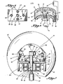
- an antenna 51 is mounted upon a stabilized platform 52 having a gimbal joint 53 which is supported upon a tower 54.
- a radome 56 is preferably provided to reduce wind loading upon the antenna 51.
- the antenna 51 mounted upon the stabilized platform 52 are both illustrated schematically, mounted upon a support 57.
- the ship 55 pitches about its center 58.
- the antenna support 57 is located a distance "L” from the center of pitch 58 of the ship 55.
- the antenna platform 52 is located a distance "H” above the plane of the center of pitch 58.
- the antenna platform 52 is mounted pivotally upon the support 57 at point "p", which in the illustrated example is a gimbal joint.
- the center of gravity of the antenna system is shown as point “c.g.”, which is located below the gimbal joint "p".
- the center of gravity "c.g.” is shown initially located upon the vertical axis 101.
- the antenna system 50 including the antenna 51 and the platform 52, will be subjected to linear acceleration forces as the ship 55 pitches about its center 58.
- the support 57 will rotate counterclockwise as shown in Figure. 2. This will result in a force acting upon the gimbal point "p" which may be resolved into a vertical component and a horizontal component.
- the horizontal component is illustrated in Figure 2, and indicated generally by the reference number "A”.
- the generally horizontal component "A" of the forces acting upon the gimbal point "p” may be thought of as causing this linear acceleration of the antenna system 50.
- Linear acceleration is sometimes also referred to as horizontal acceleration.
- the force "A” may be considered as acting upon the antenna system 50 through the point "p".
- the center of gravity “c.g.” is located a distance “D” below the point "p”.
- forces such as “A” due to linear acceleration of the antenna system 50 tend to cause the platform 52 to tilt in the direction indicated by the curved arrow 60.
- linear acceleration forces may create a turning moment about the center of gravity "c.g.”, which in the illustrated example, would be in the direction indicated by the curved arrow 60.
- the optimum vertical location of the center of gravity "c.g.” is a trade off between friction hysteresis and worst case linear accelerations that may be expected in a given application. Worst case linear accelerations may vary with different types and sizes of ships, and with different location placements aboard the ship 55. These factors may be applicable to a greater or lesser extent, dependent upon the particular application, to installations on other types of vessels, such as balloons, airplanes, offshore drilling platforms, etc.
- the center of gravity "c.g.” In minimizing errors due to horizontal linear acceleration, the center of gravity "c.g.” would ideally be located coincident with the gimbal point "p". In the example illustrated in Figure 2, if the center of gravity "c.g.” was coincident with the point "p", the force "A” due to linear acceleration would act directly upon the center of gravity "c.g.” and a turning moment in the direction of the arrow 60 would not result. That is, the distance "D" of the center of gravity from the gimbal point "p" would be zero.
- the turning moment upon the center of gravity "c.g.” is equal to the force times the distance "D” that the force acts from the center of gravity "c.g.” If the distance "D" is equal to zero, then the product of the force times the distance will also be equal to zero, resulting in a zero turning moment.
- an adjustably positionable counterweight is preferably provided to adjust the distance "D" between the center of gravity "c.g.” and the gimbal point "p.”
- the distance "D” may also be thought of as the distance between the center of gravity "c.g.” and the plane in which the gimbal axes intersect.
- An adjustably positionable counterweight may take the form of a downwardly extended bottom threaded stud extension attached to the bottom of the platform 52, and which permits the adjustment upwardly and downwardly of the counterweight by screwing the counterweight along the threaded stud extension.
- the center of gravity may be adjusted upwardly and downwardly for any particular installation to optimize target tracking performance operational results for that installation.
- the center of gravity should preferably be located as close to the gimbal point "p" as possible, offset a distance "D" which is just enough to overcome the bearing friction or the friction in the gimbal 53 plus a certain safety factor.
- the center of gravity may be offset a nominal distance of approximately 0.4 inches below the gimbal 53.
- the offset distance "D” should preferably be in the range of 0.1 to 0.8 inches, and could be within the range of 0.01 to 3.0 inches depending upon the antenna pedestal size and configuration, and the location, environment and type of motions to which the antenna systems would be subjected.
- the counterweight may not need to be adjustably positionable for a particular antenna pedestal model.
- Figure 3 illustrates schematically how an acceleration displaceable mass may be utilized to shift the center of gravity "c.g.” and compensate for destabilizing forces due to linear acceleration.
- the acceleration displaceable mass 65 occupies an initial position shown in Figure 3 by the reference numeral 65.
- an upper displaceable mass 65 and a lower displaceable mass 65 are provided.
- the acceleration displaceable mass 65 is connected to the platform 52 by a resilient member 66.
- the resilient member 66 may be a spring.
- the platform 52 and antenna system have a center of gravity 64 located below the gimbal joint 53.
- the force "A" due to linear acceleration causes the acceleration displaceable mass 65 to move to a displaced position, indicated in Figure 3 by the reference numeral 65'.
- the inertia of the acceleration displaceable mass 65 causes the acceleration displaceable mass 65 to move in the direction indicated generally by the arrow 103.
- the displacement of the acceleration displaceable mass 65 to the displaced position indicated by the numeral 65' results in a shift of the actual center of gravity to a new position indicated by the reference numeral 64'.
- the acceleration displaceable mass 65 causes the center of gravity 64 to dynamically reposition itself in response to forces due to linear acceleration in a manner which, as will be explained below, tends to offset the destabilizing effects of such forces.
- the compensating turning moment in direction 102 may be adjusted by changing the distance "X" of the displaced center of gravity 64' under a given set of conditions. In the embodiment illustrated in Figure 3, this may be accomplished by changing the magnitude of the mass 65, the distance of the mass 65 from the gimbal 53 (i.e., the length of resilient member 66), etc.
- the compensating turning moment in the direction 102 may also be made equal to the moment in direction 60 due to linear acceleration by reducing the linear acceleration moment. This may be accomplished, for example by reducing the distance "D" of the center of gravity 64 from the gimbal 53. It is desirable that the displaced center of gravity 64' not be displaced to a position lower than the initial positions of the center of gravity 64.
- an acceleration displaceable mass 65 were provided only above the platform 52, this could occur. Therefore, it is desirable in this particular illustrated embodiment, to provide an acceleration displaceable mass 65 below the plane of the platform 52 so that the distance "D" will not be lengthened when the center of gravity displaces to a position 64' in response to displacement of the acceleration displaceable mass 65'.
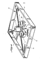
- Figure 9 illustrates a preferred form of an acceleration -displaceable mass.
- the acceleration displaceable mass 200 should take the form of a pendulum.
- the acceleration displaceable mass 200 preferably is shaped in the form of a sphere.
- a shaft 202 connects the acceleration displaceable mass 200 to a pivot point such as a gimbal 203, preferably configured as a U-Joint.
- the gimbal 203 may be a ball and socket joint, or any linkage that permits the acceleration displaceable : mass,200 freedom of movement in any horizontal direction.
- the acceleration displaceable mass 200 could be suspended from a cable.
- the gimbal 203 is connected to a support 204 that is attached to the stabilized pedestal 205.
- the pendular acceleration displaceable mass 200 is shown mounted on the stabilized pedestal 205 near the vertical axis 206 of the pedestal 205.
- the stabilized pedestal 205 is supported upon a gimbal mounting 207. Horizontal or linear acceleration forces will tend to displace the acceleration displaceable mass 200 from its initial position illustrated in Figure 9.
- the embodiment illustrated in Figure 9 may be referred to as a "compound pendulum” antenna stabilization system using an acceleration displaceable mass 200 suspended in pendular fashion.
- This embodiment has significant advantages in “start up time” and transient response.
- This embodiment also provides an acceleration displaceable mass 200 in a stable position.
- a stabilized antenna pedestal It is desirable for a stabilized antenna pedestal to have an advantageous transient response.
- Most ship notions (other than the ship's forward movement) are generally sinusoidal in nature.
- the energy from a ship's motions which is transmitted to an antenna stabilization system will sometimes contain non-sinusoidal transient components, which may be characterized, for example, as a step, a sawtooth, or an impulse function.
- Such transients can result from confused seas, bass waves, and other environmental conditions. While the energy content of transients may be relatively small, transients can cause torques to which an acceleration displaceable mass having a high second moment of inertia cannot respond with complete effectiveness.
- the disclosed stabilization system includes features intended to improve transient response and overall system performance.
- the addition of gyroscopes 209 assists in smoothing transients so that the acceleration displaceable mass 200 can effectively respond to the torque exerted upon the stabilized pedestal 205.
- the gyroscopes 209 tend to store the energy impulse introduced by transient motions, and then slowly release the energy over a period of time where it can be effectively handled by the stabilization system.
- the gyroscopes 209 have an additional function which is significant.
- the stabilized platform 205 is slightly pendular in order to provide a long term vertical reference.
- the period of oscillation for the pendular above gimbal structure can be derived, or empirically determined. It is desirable for the overall above gimbal system to have a "compound pendulum" resonant frequency 10 or more times lower than the resonant frequency of the acceleration displaceable mass 200.
- Such a low frequency resonant frequency would otherwise be costly to achieve because it would require very low friction, heavy load bearings. Such low friction bearings would be required due to the very small center of gravity offset that would be required.
- gyroscopes 209 tends to lower the above gimbal system resonant frequency greatly, and avoids the need for low friction bearings.
- the slight vibration of the gyroscope motors tends to overcome the initial friction force that would otherwise exist in the bearings of the gimbal 207.
- the above gimbal structure would also require careful static balancing at installation time, but the addition of the gyroscopes 209 makes the above gimbal system easier to balance at installation time and significantly reduces the need for preventure maintenance balancing.
- the acceleration displaceable mass 200 is suspended a distance "o" (which should not be confused with zero) from the system gimbal axes 207.
- the desirable magnitude of the ADM pendulum length "o" interacts with the weight "W of the acceleration displaceable mass 200. It is desirable to limit the ADM pendulum length "o" to a convenient length, and to improve the response time of the acceleration displaceable mass 200. It is generally desirable for the acceleration displaceable mass 200 to have a resonant frequency that is as high as possible for quick response, but the resonant frequency should not be as high as 3 Hz for vibration considerations. Due to the interaction of the acceleration displaceable mass weight "W a and the ADM pendulum length "o", by increasing the weight "W a " of the acceleration displaceable mass 200, we can make the distance "o" smaller, all other factors remaining the same.
- the ADM weight "W a " for a sphere-shaped ADM 200 should be equal to the product of the total weight of the system above the gimbal "W s " times the offset "h" of the center of gravity of the system, all divided by the ADM pendulum length "o".
- the ADM weight is determined from the formula:
- the antenna system above the gimbal 207 has a center of gravity 208 that is slightly offset a distance below the gimbal mounting 207. This slight offset is preferably just enough to overcome the friction in the gimbal 207, plus a safety factor.
- the safety factor is included to take into account aging of the bearings, deterioration of lubrication, weathering, temperature changes, and other conditions which may affect the amount of friction in the bearings.
- the C.G. offset should not be substantially long, because that would make the platform 205 unduly responsive to horizontal or linear accelerations.
- the C.G. offset provides a long term reference to gravity which tends to maintain the antenna system above the ; gimbal 207 in a vertical orientation in the absence of other motions.
- offset distance "h" of approximately 1.74 inches, without the acceleration displaceable mass 200, should produce satisfactory results for a 135 lb system.
- the center of gravity is raised.
- Adding the illustrated acceleration displaceable mass 200 should preferably raise the center of gravity offset to a static C.G. offset that is nominally about 0.4 inches.
- the center of gravity offset for the above gimbal system plus the acceleration displaceable mass should preferably be in the range of 0.1 to 0.8 inches, but could be within the range of 0.01 to 3.0 inches.
- Displacement of the acceleration displaceable mass 200 will cause the position of the center of gravity for the entire stabilization system, that is, the entire above gimbal system and the ADM 200, to shift.
- the entire stabilization system will have a dynamic center of gravity that may move and change location during operation.
- the stabilization system is designed so that the center of gravity for the entire stabilization system is dynamically repositioned to counteract torque that may result from linear acceleration forces.
- a suitable approach to constructing an embodiment of the invention should involve the steps of (1) selecting the gimbal bearings on a basis of life and shock loading, rather than emphasizing low friction; (2) determining the minimum C.G. offset distance between the gimbal axes and the center of gravity for the above gimbal system which will provide a sufficient pendular restoration force to overcome bearing friction in the gimbal 207; (3) sizing the acceleration displaceable mass 200 so that it will offset the torque affecting the above gimbal system due to horizontal or linear acceleration; and (4) determining the size of the gyroscopes 209 that is sufficient to overcome expected transient forces.
- the first three enumerated steps have been discussed above.
- One advantage of the present invention is that costly low friction gimbal bearings are not required.
- the detrmination of the minimum offset distance for the center of gravity may be done empirically.
- a safety factor typically 50 percent, is preferably added to the amount of the C.G. offset.
- the weight "W a" of the acceleration displaceable mass 200 is determined by referring to a worst case scenario for a pedestal 205 that has been tipped. If the pedestal 205 is considered as if it had been tipped 90° from a horizontal initial position, then the torque due to the weight of the above gimbal system (without the acceleration displaceable mass weight) would be equal the product of the total weight "W s " of the above gimbal system (without considering the weight of the acceleration displaceable mass) times the offset distance "h" of the center of gravity of the above gimbal system (without considering the weight of the acceleration displaceable mass).
- the weight of the acceleration displaceable mass 200 is preferably designed so that it produces a torque substantially equal to the torque calculated by the product of "W s times "h".
- the ADM torque is equal to the product of the weight "W a " of the acceleration displaceable mass 200 times the effective distance "o" between the gimbal 207 and the point where the ADM weight is applied.
- the distance "o" which may be referred to as the ADM offset, is the distance between the gimbal 207 and the ADM gimbal joint 203. If the pedestal 205 is considered to be tipped 90°, then the torque produced by the weight of the ADM 200 would be equal to "W a " times "o".
- the torque produced by the ADM may be made less than the product of "W s " times "h", and the invention should still yield satisfactory results. If the torque produced by the AD M is slightly less, then the stabilized pedestal 205 will generally always have a tendency to come to rest in an upright position because the torque due to the gravity restoration force will be slightly greater than the torque produced by the ADM 200.
- the torque produced by the acceleration displaceable mass 200 is equal to the product of "W a " " times "o".
- Various combinations of weight "W a and offset “o” may yield an equivalent ADM torque.
- the ADM offset "o” may be selected to be a convenient length.
- the weight “W “ of the ADM 200 can be calculated from the equation: For a 135 lb antenna pedestal 205, the ADM offset "o" may be selected to provide an ADM weight "W a " of 16 lbs, which in practice should be convenient, and effective.
- An alternative method for determining the appropriate size for the acceleration displaceable mass 200 involves calculating the sum of the moments about the gimbal 207.
- the sum of the moments about the gimbal 207 is equal to the second moment of inertia "Ims" for the total above gimbal system (not considering the ADM 200) multiplied times the angular acceleration "a s " for the system.
- the horizontal acceleration error torque may be considered as equal to the expression: where "h” is the offset of the center of gravity of the above-gimbal system without the acceleration displaceable mass 200, as shown in Figure 13; “M s “ is the total mass of the above gimbal system without the ADM 200; “a x “ is the magnitude of the horizontal acceleration; “S” is the error angle, as shown in Figure 13. Multiplying "a x “ by- the cosine of the "S” gives the component of the horizontal acceleration which tends to tip the platform 300, shown schematically in Figure 13. The method for calculating "a " will be discussed below. x
- the vertical acceleration torque may be considered as equal to the expression: where "a y " is the magnitude of the vertical acceleration; “h” is the C.G. offset as discussed above; “M s “ is the mass of the system as discussed above; and “S” is the error angle, as shown in Figure 13. Multiplying “a y “ by the sine of "S” gives the component of the vertical acceleration which tends to tip the platform 300. A method for calculating "a y " will be discussed below.
- the torque due to the weight of the system may be considered as equal to the expression: where "W s " is the total weight of the above gimbal system without the acceleration displaceable mass 200.
- the mass of the system "M s " “ times the acceleration of gravity “g” could be substituted for "W s ".
- "h” is the C.G. offset and "S” is the error angle, both of which are shown in Figure 13.
- Multiplying "g” times the sine of "S” will give the component of the force of gravity which tends to urge the platform 300 back to a horizontal orientation.
- Multiplying "W s " “ by the sine of "S” yields the same end result in the analysis described herein.
- a determination of the horizontal acceleration force developed and applied to the system at the gimbal 207 must take into consideration the fact that, in the environment of a ship mounted satellite antenna stabilization system, the pedestal 205 will typically be mounted high on a mast a distance removed from the pitch or roll center of the ship, as illustrated in Figure 2.
- the maximum angle that the ship will roll or pitch, and the maximum roll period may be specified, (the INMARSAT specifications are of particular interest in this case), empirically determined, or they can be based upon a worst case analysis.
- T m be the maximum roll angle that the ship motion will experience (in the INMARSAT specifications this may be 30°), and express it in radians, then the instantaneous roll angle "T” is equal to T m sin wt where "w" is equal to two pi divided by the roll period in seconds.
- the minimum roll period is eight seconds.
- the first derivative of "S x " (the horizontal distance moved at time "t") is the horizontal velocity: or
- the above expressions provide a method of determining the size of the acceleration displaceable mass 200 that is required. Referring again to Figure 13, if we sum the moments about the gimbal 207, we can determine the amount of correction torque that must be supplied by the acceleration displaceable mass 200. Without the ADM 200, the sum of the moments about the gimbal 207 is:
- the acceleration displaceable mass 200 may be considered as supplying a correction force "R” at an angle "G".
- the ADM correction torque is given by the expression: where "o" is the distance from the gimbalr207 to the pivot point 203 of the acceleration displaceable mass 200.
- This expression can then be solved to determine the magnitude of "R" that is required to correct for torques tending to tip the platform.
- Such analysis can conveniently be performed by computer calculations.
- the force "R” can be determined from a summation of moments about the pivot point 203 of the acceleration displaceable mass 200.
- the sum of the moments is equal to the second moment of intertia for the ADM 200 times the angular acceleration.
- the illustrated acceleration displaceable mass shown in Figure 9 may be modeled as a single pendulum, or as a compound pendulum. Because the length of the shaft 202 is preferably kept short to improve response time, the ADM 200 has been treated as a compound pendulum in the present analysis.
- the angle of displacement of the ADM pendulum at any point in time may be expressed as angle "G” which varies with time. Because the size of the offset "o” is very small as-compared with the size of the ship and the height "H” of the mast, we may consider "a x " and “a y “ for the acceleration displaceable mass to be the same “a x " and “a “, respectively, as derived above for the stabilized pedestal.
- the angular acceleration for the ADM 200 may be expressed as: where the acceleration displaceable mass 200 is a sphere, and the second moment of inertia of a sphere is taken as 2/5 M A r 2 + M A p 2 ; "r” is the radius of the ADM sphere, and “p” is the distance from the center of the ADM sphere to the ADM pivot point 203.
- the angle G at any given time "t” can be determined by double integration of the above expression for angular acceleration from time zero to the given time "t".
- the final step in the four enumerated steps for making a preferred embodiment of a stabilized pedestal using the teachings of the invention is the step of determining the size of the gyroscopes 209.
- the size of the gyroscopes 209 that is required depends upon the expected operational environment of the stabilized antenna system.
- the gyroscopes 209 smooth transients, and lower the resonant frequency of the above gimbal system.
- the gyroscopes 209 apply a correction force which assists the acceleration displaceable mass 200, particularly during periods of time when forces act on the platform 205 in a manner that is too quick for the acceleration displaceable mass 200 to respond.
- the sum of the moments about the gimbal 207 is analyzed, typically by computer analysis of the equation: which was derived and discussed above. Particular attention is directed to worst case scenarios or conditions.
- the gyroscopes 209 are sized to accommodate the largest expected angular acceleration "as". Such a computer analysis can produce the amount of work which must be performed by the gyroscopes 209.
- a gyroscope 209 supplies a torque equal and opposite to couples which are applied in the spin plane of the gyroscope.
- the gyroscope torque is equal to the rotational mass moment of inertia times the angular or spin velocity times the precession angular velocity.
- the rotational mass moment of inertia for a gyroscope 209 is equal to the product of the mass of the rotor or flywheel times the square of the radius of gyration.
- the gyroscopes 209 may be sized to accommodate the expected forces.
- An empirical analysis shows that much smaller gyroscopes 209 may be used in this invention, as compared to a passively stabilized antenna pedestal without an acceleration displaceable mass 200. This is a significant advantage, because the total cost of the antenna stabilization system can be significantly reduced. As a result, the usefulness of the invention is substantially increased, and it is placed within the financial reach of a larger number of users. The consequent benefit to society is apparent.
- the gyroscopes 209 also prevent the acceleration displaceable mass 200 from over correcting in the presence of a heave motion. When displaced, the acceleration displaceable mass 200 responds to heave or vertical motions. The pedestal 205 generally does not tip in response to heave motions. Thus the gyroscopes 209 smooth out the ADM's response to vetical motions in comparison to the platform's non-response.
- the size of the gyroscopes 209 can be affected by a deviation from the design relationship expressed as the ratio of the product of the weight of the above gimbal system "W s " times "h” to the weight of the ADM "W A U times " 0 ". This equation was discussed previously. In the case where: the gyroscopes 209 may be small.
- the ratio may be increased by as much as three to one, that is:
- the gyroscopes 209 will need to be larger for motions where the acceleration displaceable mass 200 over corrects.
- the ratio may be reduced to a point approaching zero. In that event, the advantages realized by including the acceleration displaceable mass 200 will be reduced, and the gyroscopes 209 will need to be larger in order to compensate.
- a spring 301 attached between the pedestal 300 and the mast 302 may be desirable.
- the spring 301 is offset a distance "K o " below the center of gravity 208.
- the spring 301 has a spring constant "K”.
- the spring correction moment is given by the equation: which is the product of the spring constant "K” times the distance that the spring was pulled K sin (T + S) x times the lever arm "K through which it pulls.
- the sum of the moments about the gimbal 207 would include a torque due to the spring:
- a spring 301 may be helpful in reducing the amount of force correction required from the acceleration displaceable mass 200 and gyroscopes 209, if the forces tending to tip the platform 300 are sinusoidal in nature.
- the spring 301 acts opposite to the horizontally applied acceleration forces.
- the spring 301 may also assist in increasing the oscillatory period of the above gimbal system, or in reducing the resonant frequency of the above gimbal system.
- a spring 301 is generally useful in the environment of a ship mounted antenna. On other vehicles where motions are not sinusoidal, a spring 301 may be detrimental.
- the spring 301 may be a torsional spring in the gimbal 207.
- the cables running between the platform 205 and the ship may act as springs 301 and assist in stabilization.
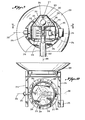
- the illustrated acceleration displaceable mass 200 is pivotally mounted within a housing 210.
- the housing 210 may be cone shaped with a flat mounting plate 204, which is adapted to receive a gimbal support shaft 211.
- the housing 210 is supported upon the stabilized pedestal 205.
- the acceleration displaceable mass 200 must be mounted so that it is in mechanical communication with the stabilized pedestal 205 in order for the ADM correction forces to be applied directly to the pedestal 205.
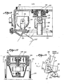
- An antenna 201 is mounted to the stabilized pedestal 205 through an elevation control that includes an elevation axis 212, and an elevation drive motor 213.
- the illustrated embodiment uses a direct drive elevation control.
- the antenna 201 can pivot, or rotate," about the elevation axis 212 in order to raise or lower the antenna pointing angle.
- the antenna 201 is supported on arms 214, which are best shown in Figure 10.
- An electronics package 215 is preferably mounted on one of the arms 214 to assist in counterbalancing the antenna 201. Other counter weights may be added to the arms 214 for balancing.
- An azimuth drive motor 216 is shown in Figure 9.
- the azimuth drive motor 216 preferably has a sprocket 217 and chain 218 drive.
- the chain 218 also engages a sprocket 219 which is fixed to an above gimbal post 220.
- the illustrated azimuth drive motor 216 is fixed to the .pedestal 205 so that the motor 216 actually "walks around" the post 220 when the azimuth position of platform 205 is changed.
- Azimuth bearings 221 are provided as shown.
- the above gimbal structure rests upon a support 222, which may be part of a mast or tower.
- the gimbal 207 includes two axes which should intersect each other, and should be at right angles to each other.
- the support 222 shown shaped as a post, extends through an opening 223 in the platform 205.
- the opening 223 is large enough to allow the platform 205 to remain horizontal as the support 222 moves underneath it.
- the support post 222 may become displaced from its initial position such that it moves to a displaced position, as shown by the ghost lines in Figure 11, indicated generally by the reference numeral 222'.
- the opening 223, shown cross-sectionally in the cut away view of Figure 11, is preferably circular.
- the gyroscope 209 preferably has a pivotal axis 225, where the gyroscope 209 is pivotally mounted to a gyro support 226.
- the gyroscope 209 is shown covered by a gyro housing 227.
- the gyroscope 209 is pivotally mounted so that it can precess in response to the application of upsetting torques to the pedestal 205.
- the gyroscope 209 preferably has a center of gravity which is slightly below the precession axis 225 in order to provide a vertical reference to the gyroscope 209.
- two gyroscopes 209 are used.
- the two gyroscopes 209 are mounted so that their precessional axes are perpendicular to each other. More than two gyroscopes 209 can be used, if desired. For example, four gyroscopes operating in two pairs could be used with equivalent results.
- Figure 12 illustrats a cutaway view of a gyroscope 209 with the cover 227 removed.
- the gyroscope 209 has a flywheel 228, which is shown in cross section.
- the flywheel 228 spins upon a shaft 229 connected to a rotor 230, which forms part of the gyroscope motor.
- the gyroscope 209 also includes a stator 231 which is supported by suitable brackets (not shown). Gyro bearings 232 are provided to facilitate rotation of the shaft 229.
- the rotor 230, shaft 229 and fly- __ wheel 228 are caused to rotate at a suitable spin velocity, which is determined by the amount of gyroscopic correction force that is needed for stabilization.
- Figure 4 illustrates an alternative embodiment of an acceleration displaceable mass 67.
- the mass 67 is supported in an initial position by resilient members or springs 68.
- the spring 68 may be conveniently disposed against a support 69.
- the support 69 takes the form of a ring.
- four resilient members 68 are illustrated, it will be appreciated that more resilient members 68 could be provided.
- the mass 67 may be maintained in an initial position by three resilient members 68 which are preferably positioned approximately 120° apart.
- the return of the acceleration displaceable mass may be accomplished through the use of preloading in the spring 68 or other means.
- an acceleration displaceable mass 109 could be mounted on air bearings to reduce the friction between the sliding mass 109 and supporting surface 105.
- the sliding mass 109 could be a fan or blower that produces sufficient air flow to support itself on an air film as illustrated in Figure 8. It may be maintained in an initial position by resilient members such as springs 68.
- a fan or blower 110 could also function simultaneously as a gyroscope to provide stabilization. In the case of air bearings, corrosion of steel bearings in a corrosive environment would not be a problem.
- the fan 110 preferably includes a motor 111 having blades 112 rotatably attached thereto.
- the blades 112 have a housing 113 covering them, which has one or more air slots 114. Rotation of the blades 112 creates an air film upon which the mass 109 floats upon surface 105.
- Figure 5 illustrates a top view of a platform 52 having four acceleration displaceable masses 67, which may be of the type shown in Figure 4.
- the platform 52 is supported by a mast 70, shown in cross-section in Figure 5.
- the acceleration displaceable masses 67 are preferably arranged symmetrically upon the platform 52 about the mast 70 to provide balance.
- Figure 6 illustrates a perspective view of yet another embodiment of an acceleration displaceable mass 71.
- the acceleration displaceable mass 71 is held in an initial position by electromagnetic forces.
- the acceleration displaceable mass 71 forms an electromagnet having a north pole 72 and a south pole 73.
- a magnetic field is induced in the acceleration displaceable mass 71 by a coil 74 which is electrically coupled to a source of electromotive force, or electrical power 75.
- the coil 74 must be wound in a particular orientation in order to achieve the desired polarity of magnetism represented by the north pole 72 and the south pole 73 of the mass 71.
- the acceleration displaceable mass 71 should preferably be fabricated from a ferrous material, such as iron.
- the acceleration displaceable mass 71 is maintained in an initial position by a support magnet 76.
- the support magnet 76 shown in a cross-sectional perspective view, may be magnetized by a coil 79, or series of coils, which are connected to a source of electromotive force, or electrical power 80.
- the coil 79 is wound so that the support magnet 76 will have a north pole 77 and a south pole 78 which correspond, respectively, to the north pole 72 and the south pole 73 of the acceleration displaceable mass 71.
- like poles 77 and 72 will repel each other.
- like poles 78 and 73 will repel each other.
- the support magnet 76 is preferably constructed in the shape of a circle or ring, the support magnet 76 will tend to urge the acceleration displaceable mass 71 resiliently toward an initial position generally in the center of the support magnet 76.
- the inertia of the mass 71 will overcome the forces of magnetism in a preferred embodiment and allow the mass 71 to displace when the forces of linear acceleration tend to accelerate the support magnets .76, which is ordinarily mechanically connected to the antenna system 50.
- FIG. 7 illustrates an embodiment of an antenna system 50, utilizing yet another embodiment of an acceleration displaceable mass 85.
- the antenna system 50 preferably has a center of gravity (not shown) located slightly below the gimbal joint 53. The location of the center of gravity may be adjusted by varying counterweights 100.
- the antenna 51 is supported by a mast 70. Acquisition of the satellite target is accomplished by elevation drive 92 which rotates the antenna about elevation axis 81, and azimuth drive 93 which rotates the antenna about azimuth axis 82.
- the mast 70 is maintained in a generally stabilized orientation by the action of the stabilized platform 52, and the pendulum effect due to the offset of the center of gravity below the gimbal 53.
- the gimbal 53 preferably has a first gimbal axis 83 which is generally perpendicular to a second gimbal axis 84.
- the right angled gimbal axes 83 and 84 preferably lie in a common horizontal plane defining the gimbal joint 53.
- This gimbal construction is similar to a "U-joint", such as used in an automobile power train system.
- the stabilized platform 52 preferably includes a gyro 61.
- the gyro 61 comprises a gyro motor 62 and gyro rotor 63.
- the motor 62 spins the rotor 63 rapidly to create a gyroscopic effect.
- the gyro 61 is preferably supported by the platform 52.
- Two gyros 61 may be provided which are pivotally mounted such that their pivot axes are at right angles to each other. Such pivoting will permit the gyros 61 to precess about their pivotal axes.
- gyros 61 are preferably mounted so that they have a center of gravity which is below their pivotal axes so that gravitational forces tend to urge the gyros 61 to a vertical orientation. This may also be thought as a precession restraining means. Either of the gyros 61 may be mounted above or below the platform 52. The gyros 61 may alternatively be tilted in a non-vertical position. In such case, it is preferable to tilt the gyros 61 in a symmetrical arrangement.
- the acceleration displaceable mass 85 compensates for otherwise destabilizing forces due to linear acceleration.
- the acceleration displaceable mass 85 shown in Figure 7 in cross-section, may take the form of a ring or, in other words, may be cylindrical in shape.
- the acceleration displaceable mass 85 is supported by a support housing 87.
- the mass 85 is free to slide horizontally within the support housing 87.
- the acceleration displaceable mass 85 is free to slide to the right or left within the support housing 87.
- Figure 7 is a two-dimensional drawing, the acceleration displaceable mass 85 is also free to slide in a direction which would be into and out of the page, and all directions intermediate thereto. That is, the acceleration displaceable mass 85 is preferably provided with 360° of freedom of movement within the horizontal plane.
- the housing 87 has an opening or aperture 104 through which the mast 70 passes, and permits freedom of movement of the support 57 and the mast 70 with respect to each other about the gimbal 53.
- the support housing 87 preferably has a lower surface 88 which is teflon coated to facilitate sliding movement of the mass 85.
- the lower surface 89 of the platform 52 is preferably teflon coated.
- the sliding mass 85 can be teflon coated and the lower surface can be glass or polished metal. The mass 85 might even be supported on three or more legs, the bottoms of which can be teflon coated.
- the acceleration displaceable mass 85 is maintained in an initial position by resilient members 86.
- the resilient members 86 may be springs.
- the acceleration displaceable mass 85 could be maintained in an initial position by electromagnetic means, by electrostatic forces, by hydraulic means, or by other means which will be apparent to those skilled in the art.
- the azimuth drive 93 is provided above the gimbal plane, or gimbal joint 53. This is significant, in that pointing errors may result if the azimuth drive is located below the gimbal 53.
- the platform 52 stabilizes the orientation of the mast 70 upon which the antenna 51 is mounted.
- the platform 52 is mechanically coupled to the antenna 51 through the mast 70. Stabilization of the platform 52 will tend to stabilize the antenna 51 and tend to maintain the pointing of the antenna 51 generally in a fixed direction during pitch and roll motions of the ship or platform upon which the support 57 is mounted.
- connection of a satellite receiver to the antenna 51 by slip rings is undesirable, and may not comply with overall system (e.g., INMARSAT) specifications. It is therefore oftentimes necessary to rapidly reposition the azimuth setting of the antenna 51 (i.e., by rotating the antenna 51 rapidly about the azimuth axis 82), in order to unwrap cables. If the platform 52 is rapidly turned, it will tend to destabilize the gyro 61. In the embodiment illustrated in Figure 7, it is not necessary to rotate the platform 52 when the azimuth setting of the antenna 51 is changed.
- overall system e.g., INMARSAT
- the platform 52 is preferably rotatably disposed upon the mast 70.
- a ring bearing 91 is provided to facilitate rotation of the platform 52 about the mast 70. Because some friction- will, in most practical systems, be present in the bearings 91, it is desirable to provide a platform azimuth drive 90 which is adapted to rotate the platform 52 about the mast 70.
- the platform drive 90 is slaved to a ship's compass, so that as the ship changes its compass heading, the orientation of the platform 52 is changed by the drive 90 so that the platform 52 remains in a generally fixed orientation with respect to compass heading. In effect, a ship will turn underneath the antenna system 50 while the antenna system 50 remains substantially motionless.
- the platform drive 90 is connected to the mast 70 - by' gears 96 and 97.
- Stepping motors are preferably used for the elevation drive 92 and the azimuth drive 93.
- Use of stepping motors provides a significant advantage in that residual torque due to the permanent magnetic fields of the stepping motors imposes a requirement for power to the elevation and azimuth axes only when heading changes occur or the vessel has moved a major distance. In many installations, neither of these conditions occur frequently, and as a result, the pedestal is in a zero power non-driven state during a high percentage of its useful life.
- An alternative embodiment of the invention could utilize selsen torquers in the place of the gyros 61. This could eliminate a more expensive gyro in exchange for two relatively inexpensive small components.
- the offsetting moment generated by the acceleration displaceable mass should be:
- the offset distance X in the case of the embodiment illustrated in Figure 4, is related to the spring constant k:
- acceleration displaceable mass so that: or or
- INMARSAT specifications provide that induced acceleration for above deck equipment should have maximum tangential accelerations of less than 0.5 g; must withstand roll motions having a period of 8 seconds, pitch motions having a period of 6 seconds, and yaw motions having a period of 50 seconds.
- the most rapid excitations are 1/(6 seconds), or 0.167 Hz.
Landscapes
- Support Of Aerials (AREA)
- Variable-Direction Aerials And Aerial Arrays (AREA)
- Pharmaceuticals Containing Other Organic And Inorganic Compounds (AREA)
- Bidet-Like Cleaning Device And Other Flush Toilet Accessories (AREA)
- Medicines Containing Material From Animals Or Micro-Organisms (AREA)
Applications Claiming Priority (4)
| Application Number | Priority Date | Filing Date | Title |
|---|---|---|---|
| US46622283A | 1983-02-14 | 1983-02-14 | |
| US466222 | 1983-02-14 | ||
| US544445 | 1983-10-21 | ||
| US06/544,445 US4596989A (en) | 1983-02-14 | 1983-10-21 | Stabilized antenna system having an acceleration displaceable mass |
Publications (1)
| Publication Number | Publication Date |
|---|---|
| EP0118729A1 true EP0118729A1 (de) | 1984-09-19 |
Family
ID=27041575
Family Applications (1)
| Application Number | Title | Priority Date | Filing Date |
|---|---|---|---|
| EP84101065A Withdrawn EP0118729A1 (de) | 1983-02-14 | 1984-02-02 | System zur Antennenplattformstabilisierung mit bei Beschleunigung ausgelenkter träger Masse |
Country Status (3)
| Country | Link |
|---|---|
| US (1) | US4596989A (de) |
| EP (1) | EP0118729A1 (de) |
| NO (1) | NO840395L (de) |
Cited By (4)
| Publication number | Priority date | Publication date | Assignee | Title |
|---|---|---|---|---|
| EP0209216A1 (de) * | 1985-05-28 | 1987-01-21 | Marconi International Marine Company Limited | Einrichtung zum Stabilisieren einer Antennenplattform |
| EP0266332A1 (de) * | 1986-09-18 | 1988-05-04 | Sait Electronics S.A. | Mechanische Vorrichtung zum Stabilisieren einer Plattform |
| WO2018093306A1 (en) | 2016-11-18 | 2018-05-24 | Saab Ab | A stabilization arrangement for stabilization of an antenna mast |
| US12432005B2 (en) | 2023-03-09 | 2025-09-30 | Honeywell International Inc. | Antenna steering through GNSS jamming, spoofing, and airplane maneuvers |
Families Citing this family (31)
| Publication number | Priority date | Publication date | Assignee | Title |
|---|---|---|---|---|
| FR2550390B1 (fr) * | 1983-08-03 | 1985-11-29 | Legall Jean Claude | Monture d'antenne a stabilisation passive |
| US4920350A (en) * | 1984-02-17 | 1990-04-24 | Comsat Telesystems, Inc. | Satellite tracking antenna system |
| FI91198C (fi) * | 1991-10-21 | 1994-05-25 | Markku Sarjala | Menetelmä mekaaniseen stabilointiin |
| US5670967A (en) * | 1991-10-21 | 1997-09-23 | Sarjala; Markku | Method and arrangement for mechanical stabilization |
| JPH05175716A (ja) * | 1991-12-19 | 1993-07-13 | Furuno Electric Co Ltd | 移動体用アンテナ指向装置 |
| US5313219A (en) * | 1992-01-27 | 1994-05-17 | International Tele-Marine Company, Inc. | Shipboard stabilized radio antenna mount system |
| US5410327A (en) * | 1992-01-27 | 1995-04-25 | Crescomm Telecommunications Services, Inc. | Shipboard stabilized radio antenna mount system |
| US5517205A (en) * | 1993-03-31 | 1996-05-14 | Kvh Industries, Inc. | Two axis mount pointing apparatus |
| AU648972B3 (en) * | 1993-10-11 | 1994-05-05 | Council of the Shire of Atherton, The | A self-levelling mount |
| US5512912A (en) * | 1994-01-28 | 1996-04-30 | Amsc Subsidiary Corporation | Marine antenna mount |
| US5922039A (en) * | 1996-09-19 | 1999-07-13 | Astral, Inc. | Actively stabilized platform system |
| US5894291A (en) * | 1996-12-05 | 1999-04-13 | Lucent Technologies, Inc. | System and method for dynamically counteracting sway in active antenna towers |
| US6052092A (en) * | 1998-01-12 | 2000-04-18 | The Detroit Edison Company | Wireless telecommunication antenna mount |
| US6859185B2 (en) * | 2003-06-11 | 2005-02-22 | Harris Corporation | Antenna assembly decoupling positioners and associated methods |
| US6950075B1 (en) * | 2003-12-08 | 2005-09-27 | The United States Of America As Represented By The Secretary Of The Navy | GPS antenna for submarine towed buoy |
| US7928345B2 (en) * | 2004-10-22 | 2011-04-19 | Ppg Industries Ohio, Inc. | Aircraft windshield defogging/deicing system and method of use thereof |
| US7437222B2 (en) * | 2005-07-28 | 2008-10-14 | The Boeing Company | Gimbal disturbance calibration and compenstion |
| US7508342B2 (en) * | 2005-11-18 | 2009-03-24 | The Boeing Company | Satellite antenna positioning system |
| US20080211730A1 (en) | 2007-01-26 | 2008-09-04 | Woosnam Calvin H | Gimbaled Mount System for Satellites |
| TWM353491U (en) * | 2008-05-16 | 2009-03-21 | Hsin-Chi Su | Antenna stabilizer |
| US8061226B2 (en) * | 2008-06-02 | 2011-11-22 | Kvh Industries, Inc. | System and method for closed loop gyroscope stabilization |
| EP2366210B1 (de) * | 2008-12-15 | 2017-09-27 | Sea Tel, Inc. | Sockel zur antennenortung |
| US8160831B1 (en) | 2009-07-15 | 2012-04-17 | Sprint Communications Company L.P. | Gyroscope monitoring for an antenna system |
| US9450286B1 (en) * | 2012-09-12 | 2016-09-20 | Viasat, Inc. | Systems, devices, and methods for stabilizing an antenna |
| US10897071B2 (en) | 2013-01-16 | 2021-01-19 | Haeco Americas, Llc | Universal adapter plate assembly |
| RU2567192C1 (ru) * | 2014-07-15 | 2015-11-10 | Федеральное государственное унитарное предприятие "Ростовский-на-Дону научно-исследовательский институт радиосвязи" (ФГУП "РНИИРС") | Двухсферовая антенная система с частичной металлизацией радиопрозрачного защитного кожуха |
| RU2567121C1 (ru) * | 2014-07-16 | 2015-11-10 | Федеральное государственное унитарное предприятие "Ростовский-на-Дону научно-исследовательский институт радиосвязи" (ФГУП "РНИИРС") | Односферовая антенная система с частичной металлизацией радиопрозрачного защитного кожуха |
| KR102405806B1 (ko) * | 2015-06-23 | 2022-06-07 | 트라네 앤드 트라네 아/에스 | 회전 가능한 안테나를 구비한 차량/선박/항공기 |
| US10283837B2 (en) | 2015-10-23 | 2019-05-07 | Viasat, Inc. | Apparatuses for mounting an antenna assembly |
| US12444836B2 (en) * | 2020-12-24 | 2025-10-14 | Ntt, Inc. | Wireless communication apparatus and control method |
| CN116027256A (zh) * | 2021-10-25 | 2023-04-28 | 华为技术有限公司 | 基站天线及其方位角的测量方法、测量装置、介质和基站 |
Citations (4)
| Publication number | Priority date | Publication date | Assignee | Title |
|---|---|---|---|---|
| DE2359877B2 (de) * | 1972-12-01 | 1975-03-20 | The Post Office, London | Anordnung zur Regelung der Ausrichtung einer Richtempfangsantenne |
| US3893123A (en) * | 1973-09-12 | 1975-07-01 | B E Ind | Combination gyro and pendulum weight stabilized platform antenna system |
| DE2544867A1 (de) * | 1974-10-07 | 1976-04-22 | Be Ind Inc | Stabilisierte plattform mit kreisel- und pendelgewichtstabilisierung fuer strahlengekoppelte antennen, photographische oder wissenschaftliche geraete o.dgl. |
| US3968496A (en) * | 1974-03-04 | 1976-07-06 | International Standard Electric Corporation | Stabilized antenna platform |
Family Cites Families (5)
| Publication number | Priority date | Publication date | Assignee | Title |
|---|---|---|---|---|
| US1310862A (en) * | 1919-07-22 | Gyroscopic apparatus | ||
| US1573343A (en) * | 1923-12-31 | 1926-02-16 | William F Holeka | Support |
| US2199294A (en) * | 1935-05-04 | 1940-04-30 | Anschuetz & Co Gmbh | Gyroscopic instrument |
| US3860931A (en) * | 1973-11-26 | 1975-01-14 | Post Office | Ship-borne gravity stabilized antenna |
| JPS57713A (en) * | 1980-06-03 | 1982-01-05 | Toshiba Corp | Body stabilizer |
-
1983
- 1983-10-21 US US06/544,445 patent/US4596989A/en not_active Expired - Fee Related
-
1984
- 1984-02-02 EP EP84101065A patent/EP0118729A1/de not_active Withdrawn
- 1984-02-02 NO NO840395A patent/NO840395L/no unknown
Patent Citations (4)
| Publication number | Priority date | Publication date | Assignee | Title |
|---|---|---|---|---|
| DE2359877B2 (de) * | 1972-12-01 | 1975-03-20 | The Post Office, London | Anordnung zur Regelung der Ausrichtung einer Richtempfangsantenne |
| US3893123A (en) * | 1973-09-12 | 1975-07-01 | B E Ind | Combination gyro and pendulum weight stabilized platform antenna system |
| US3968496A (en) * | 1974-03-04 | 1976-07-06 | International Standard Electric Corporation | Stabilized antenna platform |
| DE2544867A1 (de) * | 1974-10-07 | 1976-04-22 | Be Ind Inc | Stabilisierte plattform mit kreisel- und pendelgewichtstabilisierung fuer strahlengekoppelte antennen, photographische oder wissenschaftliche geraete o.dgl. |
Cited By (6)
| Publication number | Priority date | Publication date | Assignee | Title |
|---|---|---|---|---|
| EP0209216A1 (de) * | 1985-05-28 | 1987-01-21 | Marconi International Marine Company Limited | Einrichtung zum Stabilisieren einer Antennenplattform |
| EP0266332A1 (de) * | 1986-09-18 | 1988-05-04 | Sait Electronics S.A. | Mechanische Vorrichtung zum Stabilisieren einer Plattform |
| WO2018093306A1 (en) | 2016-11-18 | 2018-05-24 | Saab Ab | A stabilization arrangement for stabilization of an antenna mast |
| EP3542414A4 (de) * | 2016-11-18 | 2020-05-27 | Saab Ab | Stabilisierungsanordnung zur stabilisierung eines antennenmastes |
| US10714807B2 (en) | 2016-11-18 | 2020-07-14 | Saab Ab | Stabilization arrangement for stabilization of an antenna mast |
| US12432005B2 (en) | 2023-03-09 | 2025-09-30 | Honeywell International Inc. | Antenna steering through GNSS jamming, spoofing, and airplane maneuvers |
Also Published As
| Publication number | Publication date |
|---|---|
| NO840395L (no) | 1984-08-15 |
| US4596989A (en) | 1986-06-24 |
Similar Documents
| Publication | Publication Date | Title |
|---|---|---|
| US4596989A (en) | Stabilized antenna system having an acceleration displaceable mass | |
| US5419521A (en) | Three-axis pedestal | |
| US4020491A (en) | Combination gyro and pendulum weight passive antenna platform stabilization system | |
| US4621266A (en) | Device for stabilizing and aiming an antenna, more particularly on a ship | |
| US4920350A (en) | Satellite tracking antenna system | |
| US4442435A (en) | Gyro stabilization platform for scanning antenna | |
| US5922039A (en) | Actively stabilized platform system | |
| US5517205A (en) | Two axis mount pointing apparatus | |
| US3860931A (en) | Ship-borne gravity stabilized antenna | |
| NO145860B (no) | Antennestativsystem. | |
| US4582291A (en) | Mechanically stabilized platform system | |
| US4193308A (en) | Fluid dashpot gyro stabilized platform caging system | |
| JP2008228045A (ja) | 衛星追尾用アンテナ装置 | |
| CA1247234A (en) | Satellite tracking antenna system with a two-degree freedom gimballed mount | |
| WO1983001682A1 (en) | Method and apparatus for overcoming certain destabilizing torques on gyro-stabilized platforms | |
| JPS59161101A (ja) | 加速移動質量を持つた安定アンテナ装置 | |
| RU2301482C2 (ru) | Антенная система со стабилизированной плоскостью вращения обзорного корабельного радиолокатора | |
| GB2127622A (en) | Stabilisation mechanisms | |
| EP0077378B1 (de) | Mechanisch stabilisiertes plattform-system | |
| GB2173347A (en) | Stabilized mount for a platform | |
| CA1236211A (en) | Stabilization system for satellite tracking antenna | |
| JPS6111773Y2 (de) | ||
| RU176980U1 (ru) | Двухроторный гиростабилизатор | |
| JPS6148085B2 (de) | ||
| JP2517320B2 (ja) | ジャイロコンパス |
Legal Events
| Date | Code | Title | Description |
|---|---|---|---|
| PUAI | Public reference made under article 153(3) epc to a published international application that has entered the european phase |
Free format text: ORIGINAL CODE: 0009012 |
|
| AK | Designated contracting states |
Designated state(s): AT BE CH DE FR GB IT LI LU NL SE |
|
| 17P | Request for examination filed |
Effective date: 19850313 |
|
| STAA | Information on the status of an ep patent application or granted ep patent |
Free format text: STATUS: THE APPLICATION IS DEEMED TO BE WITHDRAWN |
|
| 18D | Application deemed to be withdrawn |
Effective date: 19860902 |
|
| RIN1 | Information on inventor provided before grant (corrected) |
Inventor name: SMITH, DORSEY T. Inventor name: BIESER, ALBERT H. |