EP0119497A1 - Verfahren zum Herstellen von Elektroden und Verdrahtungsstreifen - Google Patents
Verfahren zum Herstellen von Elektroden und Verdrahtungsstreifen Download PDFInfo
- Publication number
- EP0119497A1 EP0119497A1 EP84101759A EP84101759A EP0119497A1 EP 0119497 A1 EP0119497 A1 EP 0119497A1 EP 84101759 A EP84101759 A EP 84101759A EP 84101759 A EP84101759 A EP 84101759A EP 0119497 A1 EP0119497 A1 EP 0119497A1
- Authority
- EP
- European Patent Office
- Prior art keywords
- layer
- polycrystalline silicon
- aluminum
- forming
- contact hole
- Prior art date
- Legal status (The legal status is an assumption and is not a legal conclusion. Google has not performed a legal analysis and makes no representation as to the accuracy of the status listed.)
- Granted
Links
Images

Classifications
-
- H—ELECTRICITY
- H10—SEMICONDUCTOR DEVICES; ELECTRIC SOLID-STATE DEVICES NOT OTHERWISE PROVIDED FOR
- H10W—GENERIC PACKAGES, INTERCONNECTIONS, CONNECTORS OR OTHER CONSTRUCTIONAL DETAILS OF DEVICES COVERED BY CLASS H10
- H10W20/00—Interconnections in chips, wafers or substrates
- H10W20/40—Interconnections external to wafers or substrates, e.g. back-end-of-line [BEOL] metallisations or vias connecting to gate electrodes
- H10W20/41—Interconnections external to wafers or substrates, e.g. back-end-of-line [BEOL] metallisations or vias connecting to gate electrodes characterised by their conductive parts
- H10W20/44—Conductive materials thereof
- H10W20/4451—Semiconductor materials, e.g. polysilicon
-
- H—ELECTRICITY
- H10—SEMICONDUCTOR DEVICES; ELECTRIC SOLID-STATE DEVICES NOT OTHERWISE PROVIDED FOR
- H10W—GENERIC PACKAGES, INTERCONNECTIONS, CONNECTORS OR OTHER CONSTRUCTIONAL DETAILS OF DEVICES COVERED BY CLASS H10
- H10W20/00—Interconnections in chips, wafers or substrates
- H10W20/01—Manufacture or treatment
- H10W20/031—Manufacture or treatment of conductive parts of the interconnections
- H10W20/056—Manufacture or treatment of conductive parts of the interconnections by filling conductive material into holes, grooves or trenches
-
- H—ELECTRICITY
- H10—SEMICONDUCTOR DEVICES; ELECTRIC SOLID-STATE DEVICES NOT OTHERWISE PROVIDED FOR
- H10W—GENERIC PACKAGES, INTERCONNECTIONS, CONNECTORS OR OTHER CONSTRUCTIONAL DETAILS OF DEVICES COVERED BY CLASS H10
- H10W20/00—Interconnections in chips, wafers or substrates
- H10W20/01—Manufacture or treatment
- H10W20/031—Manufacture or treatment of conductive parts of the interconnections
- H10W20/062—Manufacture or treatment of conductive parts of the interconnections by smoothing of conductive parts, e.g. by planarisation
-
- H—ELECTRICITY
- H10—SEMICONDUCTOR DEVICES; ELECTRIC SOLID-STATE DEVICES NOT OTHERWISE PROVIDED FOR
- H10W—GENERIC PACKAGES, INTERCONNECTIONS, CONNECTORS OR OTHER CONSTRUCTIONAL DETAILS OF DEVICES COVERED BY CLASS H10
- H10W20/00—Interconnections in chips, wafers or substrates
- H10W20/01—Manufacture or treatment
- H10W20/031—Manufacture or treatment of conductive parts of the interconnections
- H10W20/064—Manufacture or treatment of conductive parts of the interconnections by modifying the conductivity of conductive parts, e.g. by alloying
-
- H—ELECTRICITY
- H10—SEMICONDUCTOR DEVICES; ELECTRIC SOLID-STATE DEVICES NOT OTHERWISE PROVIDED FOR
- H10W—GENERIC PACKAGES, INTERCONNECTIONS, CONNECTORS OR OTHER CONSTRUCTIONAL DETAILS OF DEVICES COVERED BY CLASS H10
- H10W20/00—Interconnections in chips, wafers or substrates
- H10W20/40—Interconnections external to wafers or substrates, e.g. back-end-of-line [BEOL] metallisations or vias connecting to gate electrodes
- H10W20/41—Interconnections external to wafers or substrates, e.g. back-end-of-line [BEOL] metallisations or vias connecting to gate electrodes characterised by their conductive parts
- H10W20/425—Barrier, adhesion or liner layers
Definitions
- the present invention relates to a method of forming a wiring layer of a semiconductor device and, more particularly, to a method of manufacturing a semiconductor device having a buried electrode structure.
- the packing density of semiconductor devices has been increasing recently due to micropatterning.
- High packing density can be achieved by, for example, micro p atterning of a contact hole.
- the most advanced technique for forming a very small contact hole is reactive ion etching (RIE).
- RIE reactive ion etching
- a very small contact hole having a very steep wall surface can be obtained by this method.
- RIE reactive ion etching
- an electrode material is deposited while the semiconductor substrate is heated.
- surface diffusion of an electrode material such as aluminum is accelerated, so that the electrode material completely fills the contact hole to achieve good electrical connection between the semiconductor region and the electrode layer.
- step coverage in the contact hole is good, so that the electrode material can be properly deposited on the semiconductor region through this contact hole.
- step coverage in the contact hole becomes poor, even if the substrate is heated.
- the electrode layer will not be electrically connected to the semiconductor region.
- silicon diffuses into the aluminum during annealing, which is performed to achieve good ohmic contact between the electrode material and substrate silicon in the contact hole.
- silicon diffuses as described above a pit is formed in the silicon layer. Aluminum is spiked in the pit. In a planar semiconductor device having a shallow p-n junction depth, the pit may reach the junction. As a result, the breakdown voltage of the p-n junction is decreased, and the reverse leakage current is increased, resulting in inconvenience.
- an interconnection structure including an electrode/wiring layer, on a semiconductor substrate, comprising the steps of:
- the substrate comprises silicon
- the recess includes a contact hole partially exposing the surface of the semiconductor substrate or the like.
- a barrier layer is formed on that surface portion of the semiconductor substrate which is exposed by the recess to prevent a reaction between the substrate silicon and aluminum.
- an alloying promotion layer made of a transition metal is formed on the aluminum layer.
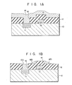
- an oxide film is formed on a semiconductor substrate such as a silicon substrate 10 having p- or n-type semiconductor regions (only one semiconductor region 11 is illustrated). The surface of the semiconductor region 11 is exposed through the oxide film.
- a conductive layer 13 such as a gate electrode with a predetermined pattern is formed on the gate oxide film.
- the first-mentioned oxide film and the gate oxide film are indicated by an oxide film 12.
- the oxide film 12 projects above the gate electrode by its thickness so as to form a stepped portion 14 with the remaining flat surface portions.
- the thickness of the oxide film 12 excluding the portion where the gate electrode is formed is about 1 ⁇ m.
- the oxide film 12 is selectively etched by RIE to form a contact hole 16 having a size of about 1 ⁇ m ⁇ so as to expose a surface portion of the semiconductor region 11.
- a relatively flat (undoped) polycrystalline silicon layer 18 is deposited on the oxide film 12 to cover the stepped portion 14 and fill the contact hole 16.
- the polycrystalline silicon layer 18 can be formed by such a technique as low pressure chemical vapor deposition (low pressure CVD) by which the very small contact hole and the stepped portion can be covered or filled with polycrystalline silicon subjected thereto. It should be noted that the polycrystalline silicon layer 18 will be more slowly alloyed with aluminum when an n-type impurity is doped therein. As is well-known, polycrystalline silicon has good step coverage characteristics as compared with those of metal such as aluminum, so that polycrystalline silicon can completely fill the very small contact hole.
- the polycrystalline silicon layer 18 is plasma-etched to leave a portion 18a filling the contact hole 16 and portions 18b covering the steps of the stepped portion 14 (Fig. 1B).
- Aluminum is then deposited to cover the entire surface (surfaces of the portions 18a and 18b, and the surface portion of the oxide film 12 which is exposed by the plasma etching) of the structure of Fig. 1B, thereby forming an aluminum layer 20 having a thickness of about 1 u m (Fig. 1C).
- the surface of the structure of Fig. 1B is cleaned by inverse sputtering using argon ions before the aluminum layer 20 is formed.
- a natural oxide film which may be formed on the portions 18a and 18b during the plasma etching would impair the contact with the aluminum layer 20, and thus the inverse sputtering is used to remove it. It should be noted that the substrate need not be heated when aluminum is deposited.
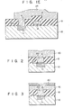
- Fig. lC is annealed at a temperature of, for example, about 450°C for 30 minutes.
- silicon is alloyed with aluminum in the portions 18b on the steps of the stepped portion 14, thereby producing a wiring layer with the remaining portion of the aluminum layer.
- the portion of the aluminum layer 20 which is adjacent to the electrode layer 18a' is converted to the same alloy as that of the electrode layer 18a'.
- an .electrode/wiring layer 22, which includes the electrode layer 18a' is formed (Fig. lD).
- the electrode/wiring layer 22 is patterned to obtain a predetermined electrode/wiring structure 24 (Fig. lE). Alloying may be performed after this patterning.
- polycrystalline silicon with good step coverage characteristics is used to substantially completely fill a recess (the contact hole 16 and the stepped portion 14) of the insulating pattern 12 on the substrate.
- Polycrystalline silicon in the recess is reacted with aluminum to form an alloy. Therefore, the electrode layer finally obtained is properly connected to the substrate 10 (semiconductor region 11) through the contact hole 16 (even if the contact hole 16 is very small), thereby preventing incomplete contact due to disconnection.
- polycrystalline silicon in the contact hole 16 is substantially converted to an alloy with aluminum, so that the contact resistance between the alloy and the substrate is sufficiently low.
- the substrate need not be heated when the aluminum layer 20 is formed, so that operability is increased and the heater can be eliminated, thus decreasing the manufacturing cost. Therefore, semiconductor devices with higher reliability can be obtained with good yield according to the method of the present invention.
- Fig. 2 is substantially the same as that of Figs. lA to lE, except that a transition metal (e.g., titanium, molybdenum, niobium or platinum; preferably titanium) silicide barrier layer 30 is formed on a portion of the surface of the semiconductor region 11 which is exposed through the contact hole 16.
- the silicide barrier layer 30 is formed by deposition of a transition metal and subsequent heating to cause a chemical reaction between the transition metal and substrate silicon. A reaction which may take place between the aluminum layer 20 and the silicon substrate can be prevented by the presence of the silicide barrier layer 30.
- a transition metal e.g., titanium, molybdenum, niobium or platinum
- the transition metal tends to be coverted to a silicide, so that silicon atoms are absorbed from the portion 18a during annealing. As a result, the diffusion of the silicon atoms into the aluminum layer 20 can be accelerated.
- the aluminum layer 42 including the alloying promotion layer 40 is formed such that the transition metal layer 40 is formed after the aluminum layer 20, as described with reference to Fig. lC, and then aluminum is deposited again thereon.
- the transition metal is preferably a material which can be easily converted to a silicide at a relatively low temperature, and which provides a silicide with a high silicon content (i.e., the material which can combine with the greater number of silicon atoms).
- titanium is the most preferred transition metal.
- the main feature of the present invention lies in the fact that polycrystalline silicon is left only in the recess of the insulating structure, and thereafter aluminum is deposited.
- polycrystalline silicon is present under the entire area of the aluminum layer, as described with reference to the above-mentioned Japanese Patent Disclosure, polycrystalline silicon is excessive with respect to aluminum. Therefore, all the polycrystalline silicon cannot be converted into the alloy.
- Polycrystalline silicon which is spaced apart from aluminum is left non-reacted. Typically this occurs in the contact hole. According to this conventional method, an alloy spike into the silicon substrate can be prevented, but polycrystalline silicon in the contact hole is left non-reacted. Therefore, a low contact resistance between the polycrystalline silicon layer and the silicon substrate cannot be obtained.
- polycrystalline silicon is left only in the recess, so that the amount of polycrystalline silicon is small with respect to that of aluminum.
- all the polycrystalline silicon can be completely converted into the alloy, and an electrode structure with good substrate contact can be formed without causing an alloy spike.
Landscapes
- Internal Circuitry In Semiconductor Integrated Circuit Devices (AREA)
- Electrodes Of Semiconductors (AREA)
Applications Claiming Priority (2)
| Application Number | Priority Date | Filing Date | Title |
|---|---|---|---|
| JP28097/83 | 1983-02-22 | ||
| JP58028097A JPS59154040A (ja) | 1983-02-22 | 1983-02-22 | 半導体装置の製造方法 |
Publications (2)
| Publication Number | Publication Date |
|---|---|
| EP0119497A1 true EP0119497A1 (de) | 1984-09-26 |
| EP0119497B1 EP0119497B1 (de) | 1987-05-06 |
Family
ID=12239283
Family Applications (1)
| Application Number | Title | Priority Date | Filing Date |
|---|---|---|---|
| EP84101759A Expired EP0119497B1 (de) | 1983-02-22 | 1984-02-20 | Verfahren zum Herstellen von Elektroden und Verdrahtungsstreifen |
Country Status (4)
| Country | Link |
|---|---|
| US (1) | US4538344A (de) |
| EP (1) | EP0119497B1 (de) |
| JP (1) | JPS59154040A (de) |
| DE (1) | DE3463589D1 (de) |
Cited By (11)
| Publication number | Priority date | Publication date | Assignee | Title |
|---|---|---|---|---|
| EP0165085A1 (de) * | 1984-04-13 | 1985-12-18 | STMicroelectronics S.A. | Verfahren zur Herstellung von Aluminiumkontakten mit einer integrierten Schaltung durch eine dicke Isolierschicht hindurch |
| EP0170544A1 (de) * | 1984-06-14 | 1986-02-05 | Commissariat A L'energie Atomique | Verfahren zur Selbstjustierung eines Verbindungsleiters über einem elektrischen Kontaktloch einer integrierten Schaltung |
| EP0199030A3 (de) * | 1985-04-11 | 1987-08-26 | Siemens Aktiengesellschaft | Verfahren zum Herstellen einer Mehrlagenverdrahtung von integrierten Halbleiterschaltungen mit mindestens einer aus einer Aluminiumlegierung bestehenden Leitbahnebene mit Kontaktlochauffüllung |
| EP0123309A3 (en) * | 1983-04-25 | 1987-09-30 | Siemens Aktiengesellschaft Berlin Und Munchen | Method of producing stable, low ohmic contacts in integrated semiconductor circuits |
| EP0267831A1 (de) * | 1986-10-17 | 1988-05-18 | Thomson Components-Mostek Corporation | Planarisationstechnik für Doppelmetallisierung |
| WO1988004831A1 (en) * | 1986-12-19 | 1988-06-30 | Hughes Aircraft Company | Conductive plug for contacts and vias on integrated circuits |
| US4837051A (en) * | 1986-12-19 | 1989-06-06 | Hughes Aircraft Company | Conductive plug for contacts and vias on integrated circuits |
| EP0444695A3 (en) * | 1990-03-02 | 1992-04-15 | Kabushiki Kaisha Toshiba | Semiconductor device having multilayered wiring structure and method of manufacturing the same |
| US5238874A (en) * | 1989-11-09 | 1993-08-24 | Nec Corporation | Fabrication method for laminated films comprising Al-Si-Co alloy film and refractory metal silioide copper film |
| EP0549199A3 (de) * | 1991-12-27 | 1994-08-03 | At & T Corp | |
| EP1909319A1 (de) * | 2006-10-03 | 2008-04-09 | STMicroelectronics (Crolles 2) SAS | Niederohmiger Kontakt |
Families Citing this family (15)
| Publication number | Priority date | Publication date | Assignee | Title |
|---|---|---|---|---|
| US4714686A (en) * | 1985-07-31 | 1987-12-22 | Advanced Micro Devices, Inc. | Method of forming contact plugs for planarized integrated circuits |
| US4808552A (en) * | 1985-09-11 | 1989-02-28 | Texas Instruments Incorporated | Process for making vertically-oriented interconnections for VLSI devices |
| JPS62102559A (ja) * | 1985-10-29 | 1987-05-13 | Mitsubishi Electric Corp | 半導体装置及び製造方法 |
| US4818723A (en) * | 1985-11-27 | 1989-04-04 | Advanced Micro Devices, Inc. | Silicide contact plug formation technique |
| US4835118A (en) * | 1986-09-08 | 1989-05-30 | Inmos Corporation | Non-destructive energy beam activated conductive links |
| ATE150585T1 (de) * | 1990-05-31 | 1997-04-15 | Canon Kk | Verfahren zur herstellung einer halbleitervorrichtung mit einer verdrahtungsstruktur hoher dichte |
| JP2841976B2 (ja) * | 1990-11-28 | 1998-12-24 | 日本電気株式会社 | 半導体装置およびその製造方法 |
| US5293512A (en) * | 1991-02-13 | 1994-03-08 | Nec Corporation | Semiconductor device having a groove type isolation region |
| TW520072U (en) * | 1991-07-08 | 2003-02-01 | Samsung Electronics Co Ltd | A semiconductor device having a multi-layer metal contact |
| US5637525A (en) * | 1995-10-20 | 1997-06-10 | Micron Technology, Inc. | Method of forming a CMOS circuitry |
| US5994218A (en) * | 1996-09-30 | 1999-11-30 | Kabushiki Kaisha Toshiba | Method of forming electrical connections for a semiconductor device |
| TW347570B (en) | 1996-12-24 | 1998-12-11 | Toshiba Co Ltd | Semiconductor device and method for manufacturing the same |
| US6103572A (en) * | 1997-02-07 | 2000-08-15 | Citizen Watch Co., Ltd. | Method of fabricating a semiconductor nonvolatile storage device |
| US6303509B1 (en) * | 1999-10-29 | 2001-10-16 | Taiwan Semiconductor Manufacturing Company | Method to calibrate the wafer transfer for oxide etcher (with clamp) |
| JP2004260101A (ja) | 2003-02-27 | 2004-09-16 | Rohm Co Ltd | 半導体装置の製造方法 |
Citations (5)
| Publication number | Priority date | Publication date | Assignee | Title |
|---|---|---|---|---|
| US4291322A (en) * | 1979-07-30 | 1981-09-22 | Bell Telephone Laboratories, Incorporated | Structure for shallow junction MOS circuits |
| GB2075255A (en) * | 1980-03-26 | 1981-11-11 | Nippon Electric Co | Contact electrodes for semiconductor devices |
| EP0055161A1 (de) * | 1980-12-09 | 1982-06-30 | FAIRCHILD CAMERA & INSTRUMENT CORPORATION | Mehrschichtige Metallsilizid-Verbindungsleiter für integrierte Schaltungen |
| US4361599A (en) * | 1981-03-23 | 1982-11-30 | National Semiconductor Corporation | Method of forming plasma etched semiconductor contacts |
| DE3218974A1 (de) * | 1981-05-20 | 1982-12-16 | Mitsubishi Electric Corp | Leiterverbindungsschicht fuer halbleitervorrichtungen und verfahren zu ihrer herstellung |
Family Cites Families (12)
| Publication number | Priority date | Publication date | Assignee | Title |
|---|---|---|---|---|
| JPS5218670B2 (de) * | 1971-08-11 | 1977-05-23 | ||
| US3906540A (en) * | 1973-04-02 | 1975-09-16 | Nat Semiconductor Corp | Metal-silicide Schottky diode employing an aluminum connector |
| US3918149A (en) * | 1974-06-28 | 1975-11-11 | Intel Corp | Al/Si metallization process |
| JPS5114798A (ja) * | 1974-07-27 | 1976-02-05 | Nippon Oils & Fats Co Ltd | Kinkyuhinanyoratsukasan |
| US3996656A (en) * | 1974-08-28 | 1976-12-14 | Harris Corporation | Normally off Schottky barrier field effect transistor and method of fabrication |
| JPS5317393A (en) * | 1976-07-31 | 1978-02-17 | Mitsubishi Heavy Ind Ltd | Commodities delivery detector |
| JPS5374888A (en) * | 1976-12-15 | 1978-07-03 | Fujitsu Ltd | Manufacture of semiconductor device |
| JPS5444482A (en) * | 1977-09-14 | 1979-04-07 | Matsushita Electric Ind Co Ltd | Mos type semiconductor device and its manufacture |
| US4358891A (en) * | 1979-06-22 | 1982-11-16 | Burroughs Corporation | Method of forming a metal semiconductor field effect transistor |
| US4316209A (en) * | 1979-08-31 | 1982-02-16 | International Business Machines Corporation | Metal/silicon contact and methods of fabrication thereof |
| US4322453A (en) * | 1980-12-08 | 1982-03-30 | International Business Machines Corporation | Conductivity WSi2 (tungsten silicide) films by Pt preanneal layering |
| JPS5816337A (ja) * | 1981-07-22 | 1983-01-31 | Hitachi Ltd | プラント情報伝送システム |
-
1983
- 1983-02-22 JP JP58028097A patent/JPS59154040A/ja active Granted
-
1984
- 1984-02-20 EP EP84101759A patent/EP0119497B1/de not_active Expired
- 1984-02-20 DE DE8484101759T patent/DE3463589D1/de not_active Expired
- 1984-02-21 US US06/582,223 patent/US4538344A/en not_active Expired - Lifetime
Patent Citations (5)
| Publication number | Priority date | Publication date | Assignee | Title |
|---|---|---|---|---|
| US4291322A (en) * | 1979-07-30 | 1981-09-22 | Bell Telephone Laboratories, Incorporated | Structure for shallow junction MOS circuits |
| GB2075255A (en) * | 1980-03-26 | 1981-11-11 | Nippon Electric Co | Contact electrodes for semiconductor devices |
| EP0055161A1 (de) * | 1980-12-09 | 1982-06-30 | FAIRCHILD CAMERA & INSTRUMENT CORPORATION | Mehrschichtige Metallsilizid-Verbindungsleiter für integrierte Schaltungen |
| US4361599A (en) * | 1981-03-23 | 1982-11-30 | National Semiconductor Corporation | Method of forming plasma etched semiconductor contacts |
| DE3218974A1 (de) * | 1981-05-20 | 1982-12-16 | Mitsubishi Electric Corp | Leiterverbindungsschicht fuer halbleitervorrichtungen und verfahren zu ihrer herstellung |
Cited By (13)
| Publication number | Priority date | Publication date | Assignee | Title |
|---|---|---|---|---|
| EP0123309A3 (en) * | 1983-04-25 | 1987-09-30 | Siemens Aktiengesellschaft Berlin Und Munchen | Method of producing stable, low ohmic contacts in integrated semiconductor circuits |
| EP0165085A1 (de) * | 1984-04-13 | 1985-12-18 | STMicroelectronics S.A. | Verfahren zur Herstellung von Aluminiumkontakten mit einer integrierten Schaltung durch eine dicke Isolierschicht hindurch |
| EP0170544A1 (de) * | 1984-06-14 | 1986-02-05 | Commissariat A L'energie Atomique | Verfahren zur Selbstjustierung eines Verbindungsleiters über einem elektrischen Kontaktloch einer integrierten Schaltung |
| EP0199030A3 (de) * | 1985-04-11 | 1987-08-26 | Siemens Aktiengesellschaft | Verfahren zum Herstellen einer Mehrlagenverdrahtung von integrierten Halbleiterschaltungen mit mindestens einer aus einer Aluminiumlegierung bestehenden Leitbahnebene mit Kontaktlochauffüllung |
| EP0267831A1 (de) * | 1986-10-17 | 1988-05-18 | Thomson Components-Mostek Corporation | Planarisationstechnik für Doppelmetallisierung |
| US4837051A (en) * | 1986-12-19 | 1989-06-06 | Hughes Aircraft Company | Conductive plug for contacts and vias on integrated circuits |
| WO1988004831A1 (en) * | 1986-12-19 | 1988-06-30 | Hughes Aircraft Company | Conductive plug for contacts and vias on integrated circuits |
| US5238874A (en) * | 1989-11-09 | 1993-08-24 | Nec Corporation | Fabrication method for laminated films comprising Al-Si-Co alloy film and refractory metal silioide copper film |
| EP0444695A3 (en) * | 1990-03-02 | 1992-04-15 | Kabushiki Kaisha Toshiba | Semiconductor device having multilayered wiring structure and method of manufacturing the same |
| US5462893A (en) * | 1990-03-02 | 1995-10-31 | Kabushiki Kaisha Toshiba | Method of making a semiconductor device with sidewall etch stopper and wide through-hole having multilayered wiring structure |
| US5543360A (en) * | 1990-03-02 | 1996-08-06 | Kabushiki Kaisha Toshiba | Method of making a semiconductor device with sidewall etch stopper and wide through-hole having multilayered wiring structure |
| EP0549199A3 (de) * | 1991-12-27 | 1994-08-03 | At & T Corp | |
| EP1909319A1 (de) * | 2006-10-03 | 2008-04-09 | STMicroelectronics (Crolles 2) SAS | Niederohmiger Kontakt |
Also Published As
| Publication number | Publication date |
|---|---|
| US4538344A (en) | 1985-09-03 |
| DE3463589D1 (en) | 1987-06-11 |
| JPS59154040A (ja) | 1984-09-03 |
| JPH0220140B2 (de) | 1990-05-08 |
| EP0119497B1 (de) | 1987-05-06 |
Similar Documents
| Publication | Publication Date | Title |
|---|---|---|
| EP0119497B1 (de) | Verfahren zum Herstellen von Elektroden und Verdrahtungsstreifen | |
| EP0249780B1 (de) | Halbleitervorrichtung mit Leiterbahn, die gute Kantenbekleidung zu den Kontaktlöchern besitzt | |
| EP0506426B1 (de) | Metallisierung eines integrierten Schaltkreises mit Nullkontaktanforderung des Gehäuses und Verfahren zu seiner Herstellung | |
| US4884123A (en) | Contact plug and interconnect employing a barrier lining and a backfilled conductor material | |
| US4800177A (en) | Semiconductor device having multilayer silicide contact system and process of fabrication thereof | |
| US4960732A (en) | Contact plug and interconnect employing a barrier lining and a backfilled conductor material | |
| KR100243286B1 (ko) | 반도체 장치의 제조방법 | |
| JP3413876B2 (ja) | 半導体装置 | |
| US6495919B2 (en) | Conductive implant structure in a dielectric | |
| US5103272A (en) | Semiconductor device and a method for manufacturing the same | |
| US4562640A (en) | Method of manufacturing stable, low resistance contacts in integrated semiconductor circuits | |
| EP0174773A2 (de) | Halbleiteranordnung mit Verbindungsschichten | |
| EP0464791B1 (de) | Verfahren zum Absenken von Material mit niedrigem Widerstand in einem Kontaktloch | |
| EP0097848A1 (de) | Verfahren zum Herstellen eines Halbleitervorrichtung | |
| EP0380327A2 (de) | Struktur einer Halbleiteranordnung mit einer trichterförmigen Verbindung zwischen den Ebenen | |
| US4900257A (en) | Method of making a polycide gate using a titanium nitride capping layer | |
| US5210043A (en) | Process for producing semiconductor device | |
| KR0173458B1 (ko) | 반도체집적회로 및 그 제조방법 | |
| US5843837A (en) | Method of contact hole burying | |
| JPH07130682A (ja) | 半導体装置の製造方法 | |
| EP0566253A1 (de) | Herstellungsverfahren für Kontaktstrukturen in integrierten Schaltungen | |
| US5933719A (en) | Method of manufacturing a semiconductor device | |
| US6239015B1 (en) | Semiconductor device having polysilicon interconnections and method of making same | |
| JPS6046024A (ja) | 半導体装置の製造方法 | |
| KR100250744B1 (ko) | 반도체 소자의 폴리사이드층 형성 방법 |
Legal Events
| Date | Code | Title | Description |
|---|---|---|---|
| PUAI | Public reference made under article 153(3) epc to a published international application that has entered the european phase |
Free format text: ORIGINAL CODE: 0009012 |
|
| 17P | Request for examination filed |
Effective date: 19840316 |
|
| AK | Designated contracting states |
Designated state(s): DE FR GB IT |
|
| GRAA | (expected) grant |
Free format text: ORIGINAL CODE: 0009210 |
|
| AK | Designated contracting states |
Kind code of ref document: B1 Designated state(s): DE FR GB IT |
|
| ITF | It: translation for a ep patent filed | ||
| REF | Corresponds to: |
Ref document number: 3463589 Country of ref document: DE Date of ref document: 19870611 |
|
| ET | Fr: translation filed | ||
| PLBE | No opposition filed within time limit |
Free format text: ORIGINAL CODE: 0009261 |
|
| STAA | Information on the status of an ep patent application or granted ep patent |
Free format text: STATUS: NO OPPOSITION FILED WITHIN TIME LIMIT |
|
| 26N | No opposition filed | ||
| ITTA | It: last paid annual fee | ||
| PGFP | Annual fee paid to national office [announced via postgrant information from national office to epo] |
Ref country code: GB Payment date: 19970211 Year of fee payment: 14 Ref country code: FR Payment date: 19970211 Year of fee payment: 14 |
|
| PGFP | Annual fee paid to national office [announced via postgrant information from national office to epo] |
Ref country code: DE Payment date: 19970228 Year of fee payment: 14 |
|
| PG25 | Lapsed in a contracting state [announced via postgrant information from national office to epo] |
Ref country code: GB Free format text: LAPSE BECAUSE OF NON-PAYMENT OF DUE FEES Effective date: 19980220 |
|
| PG25 | Lapsed in a contracting state [announced via postgrant information from national office to epo] |
Ref country code: FR Free format text: THE PATENT HAS BEEN ANNULLED BY A DECISION OF A NATIONAL AUTHORITY Effective date: 19980228 |
|
| GBPC | Gb: european patent ceased through non-payment of renewal fee |
Effective date: 19980220 |
|
| PG25 | Lapsed in a contracting state [announced via postgrant information from national office to epo] |
Ref country code: DE Free format text: LAPSE BECAUSE OF NON-PAYMENT OF DUE FEES Effective date: 19981103 |
|
| REG | Reference to a national code |
Ref country code: FR Ref legal event code: ST |