EP0120713A2 - Röntgenstrahlenbewegungskamera - Google Patents
Röntgenstrahlenbewegungskamera Download PDFInfo
- Publication number
- EP0120713A2 EP0120713A2 EP84302129A EP84302129A EP0120713A2 EP 0120713 A2 EP0120713 A2 EP 0120713A2 EP 84302129 A EP84302129 A EP 84302129A EP 84302129 A EP84302129 A EP 84302129A EP 0120713 A2 EP0120713 A2 EP 0120713A2
- Authority
- EP
- European Patent Office
- Prior art keywords
- sample
- axis
- camera
- support
- drive means
- Prior art date
- Legal status (The legal status is an assumption and is not a legal conclusion. Google has not performed a legal analysis and makes no representation as to the accuracy of the status listed.)
- Ceased
Links
- 238000002441 X-ray diffraction Methods 0.000 title claims abstract description 11
- 230000033001 locomotion Effects 0.000 claims description 33
- 239000000843 powder Substances 0.000 description 13
- 238000000034 method Methods 0.000 description 9
- 239000013078 crystal Substances 0.000 description 8
- 239000004020 conductor Substances 0.000 description 6
- 238000005169 Debye-Scherrer Methods 0.000 description 4
- 238000004458 analytical method Methods 0.000 description 4
- 230000007246 mechanism Effects 0.000 description 3
- 230000000694 effects Effects 0.000 description 2
- 238000010276 construction Methods 0.000 description 1
- 238000002447 crystallographic data Methods 0.000 description 1
- 238000010586 diagram Methods 0.000 description 1
- 239000002184 metal Substances 0.000 description 1
- 238000012856 packing Methods 0.000 description 1
- 239000002245 particle Substances 0.000 description 1
Images

Classifications
-
- G—PHYSICS
- G01—MEASURING; TESTING
- G01N—INVESTIGATING OR ANALYSING MATERIALS BY DETERMINING THEIR CHEMICAL OR PHYSICAL PROPERTIES
- G01N23/00—Investigating or analysing materials by the use of wave or particle radiation, e.g. X-rays or neutrons, not covered by groups G01N3/00 – G01N17/00, G01N21/00 or G01N22/00
- G01N23/20—Investigating or analysing materials by the use of wave or particle radiation, e.g. X-rays or neutrons, not covered by groups G01N3/00 – G01N17/00, G01N21/00 or G01N22/00 by using diffraction of the radiation by the materials, e.g. for investigating crystal structure; by using scattering of the radiation by the materials, e.g. for investigating non-crystalline materials; by using reflection of the radiation by the materials
- G01N23/205—Investigating or analysing materials by the use of wave or particle radiation, e.g. X-rays or neutrons, not covered by groups G01N3/00 – G01N17/00, G01N21/00 or G01N22/00 by using diffraction of the radiation by the materials, e.g. for investigating crystal structure; by using scattering of the radiation by the materials, e.g. for investigating non-crystalline materials; by using reflection of the radiation by the materials using diffraction cameras
Definitions
- the present invention relates to cameras for X-ray diffraction analysis of crystalline samples to determine, for example, unit cell geometry, unit cell size, and crystalline structure (arrangement of atoms within the unit cell).
- the present invention also relates to X-ray goniometers.
- Known cameras utilise an X-ray collinating system which directs a narrow beam of X-radiation at a specimen which results in the recording on a film of an X-ray diffraction pattern of the specimen.
- the essential feature of the powder diffraction technique is that a narrow beam of monochromatic X-rays impinge upon a crystalline powder composed of fine randomly oriented particles - ideally, all possible orientations of all possible lattice planes are present so that the X-ray beam will always find some crystallites of the proper orientation to fulfill the Bragg condition for reflection.
- Gandolfi (Miner.Petrogr.Acta, 13 pp 67-74) used a Debye-Scherrer camera which contained two sample holders, the first of which was inclined at 45° to the vertical axis, after the initial exposure was made in this fashion. The sample was then transferred to a vertical sample holder and a second exposure made using the normal Debye-Scherrer technique. Unless the sample is placed precisely concentric with the original sample, variations can occur in both the position and intensity of the diffraction lines. Moreover the instrument will not record a complete powder diagram for a triclinic crystal and hence will not provide a random sample of reciprocal space.
- random motion postulates that such motion be completely unpredictable in the time domain. From this it must be concluded that with respect to the X-ray beam there should be the same probability that every possible orientation of the crystal planes will occur with equal likelihood in a sample undergoing random motion. As far as random motion is concerned its instantaneous vector can be described in terms of motion about the three co-ordinate axes together with motion along those axes. In order therefore to generate random motion all of these motions should be available to the sample. Again ideally there should be no pattern of recurrences. In practice this is virtually impossible to achieve in any mechanical system.
- U.S. Patent No 4 413 354 there is described an X-ray diffraction camera having a hypocycloidal gear train adapted to cause rotation of the sample within the camera about two generally normal axes.
- the present invention although not restricted to use with this camera, is particularly useful when adapted for operation with this camera. More particularly, US Patent No 4 413 354 attempts to approximate random motion of the sample by approximating random rotation about two generally normal axes. The camera of this US Patent however lacks any random motion which can be attributed to linear motion of the sample.
- an X-ray diffraction camera having a sample support to position the sample at a predetermined location, means to receive and support a film, means to direct X-rays at the sample so that scattered rays leaving said sample expose said film, and drive means to cause motion of said sample support so that movement of said sample approximates random motion, said drive means being adapted to rotate said sample support about at least one axis and to move said sample linearly intermittently during rotation of said sample.
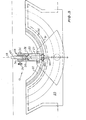
- FIGs 1 to 3 there is schematically depicted an X-ray diffraction camera 10.
- the camera 10 is substantially identical in construction to the camera of US Patent 4 413 354 except that the sample holder 13 which receives a crystalline sample is subjected to additional rotation with linear motion being super-imposed upon the rotational movement of the sample.
- the camera 10 includes a cylindrical housing 11 having an internal surface 12 which receives a strip of film so that the film forms the configuration of a cylinder.
- Located centrally of the housing 11 is a sample holder 13 which receives the crystalline sample to be subjected to a narrow beam of monochromatic X-rays with the result that the X-rays will be scattered by refracting planes of the sample.
- the scattered rays impinge on the film.
- the sample holder 13 is mounted on a sample support 14 which is movably mounted on a base 18.
- the base 18 is rotatably supported on a main frame 19. Operation of the camera 10 is basically as described in US Patent 4 413 354 in that the sample holder 13 is rotated about the two axes A and B.
- random motion of the sample is more closely approximated by rotating the sample holder 13 about a third axis which is the axis of a shaft 20 supporting the holder 13.
- the shaft 20 is caused to oscillate about the axis A in accordance with movement of the sample support 14.
- the shaft 20 is rotatably supported by the sample 14 and includes a pinion gear 21 fixed to the shaft 20.
- the pinion gear 21 is adapted to engage a rack 22 formed on one of the support plates 23 forming part of the base 18.
- the sample holder 13 includes an adjustable guide assembly 24 including guide plates 36 and threaded adjustment member 26 which are adjustable so as to secure the sample 25 in position while allowing linear movement thereof along the axis of the shaft 20.
- a solenoid 27 which causes linear reciprocation of a metal pin 28 to which a sample 25 is secured.
- the pin 28 has a flange 29 against which the spring 30 bears to bias the pin 28 to the position depicted.
- the solenoid 27 receives intermittent DC current from two strips of conductor 31 and 32 which in turn receive electric power from lines 33 and 34 fixed to the base 19. Contact of the conductors 31 and 32 with the lines 33 and 34 is achieved by brushes. Additionally the solenoid would be provided with brushes 35 which contact the conductors 31 and 32.
- the solenoid 27 would be mounted concentric of the shaft 20 and would pass through the centre of the pinion gear 21. To provide intermittent linear motion of the pin 28, and therefore the sample 25, the conductors 31 and 32 would have intermittent patches which would deactivate the solenoid 27. As the support 14 is caused to rotate about the axis A, the brushes 35 would pass along the conductors 31 and 32 thereby engaging the conductive portions exposed of the conductors 31 and 32 to thus cause intermittent actuation of the solenoid 27.
- the abovedescribed preferred embodiment provides the motion required to achieve randomness in respect of motion of the sample 25.
- relatively prime-number gear ratios are used in all the drive mechanisms which control the motion about the three co-ordinated axes.
- the sample is vibrated along the instantaneous axis of rotation of the shaft 20 by intermittent actuation of the solenoid 2 7.
- the abovedescribed preferred form of the present invention introduces an extra rotational movement to the sample which rotational movement changes in direction. In this way motion of the sample more closely approximates random motion with respect to the X-ray beam.
Landscapes
- Chemical & Material Sciences (AREA)
- Crystallography & Structural Chemistry (AREA)
- Physics & Mathematics (AREA)
- Health & Medical Sciences (AREA)
- Life Sciences & Earth Sciences (AREA)
- Analytical Chemistry (AREA)
- Biochemistry (AREA)
- General Health & Medical Sciences (AREA)
- General Physics & Mathematics (AREA)
- Immunology (AREA)
- Pathology (AREA)
- Analysing Materials By The Use Of Radiation (AREA)
Applications Claiming Priority (2)
| Application Number | Priority Date | Filing Date | Title |
|---|---|---|---|
| AU866283 | 1983-03-29 | ||
| AU8662/83 | 1983-03-29 |
Publications (2)
| Publication Number | Publication Date |
|---|---|
| EP0120713A2 true EP0120713A2 (de) | 1984-10-03 |
| EP0120713A3 EP0120713A3 (de) | 1985-09-18 |
Family
ID=3699379
Family Applications (1)
| Application Number | Title | Priority Date | Filing Date |
|---|---|---|---|
| EP84302129A Ceased EP0120713A3 (de) | 1983-03-29 | 1984-03-29 | Röntgenstrahlenbewegungskamera |
Country Status (4)
| Country | Link |
|---|---|
| US (1) | US4573182A (de) |
| EP (1) | EP0120713A3 (de) |
| JP (1) | JPS59218942A (de) |
| CA (1) | CA1216682A (de) |
Families Citing this family (2)
| Publication number | Priority date | Publication date | Assignee | Title |
|---|---|---|---|---|
| JPH0731140B2 (ja) * | 1986-04-28 | 1995-04-10 | 新日本製鐵株式会社 | エネルギ−分散型x線回折装置 |
| US5181233A (en) * | 1991-11-08 | 1993-01-19 | Florida State University | Specimen holder |
Family Cites Families (4)
| Publication number | Priority date | Publication date | Assignee | Title |
|---|---|---|---|---|
| US2317329A (en) * | 1942-10-20 | 1943-04-20 | American Cyanamid Co | Specimen holder for x-ray analyses |
| US4203034A (en) * | 1978-06-01 | 1980-05-13 | University Of Florida Board Of Regents | Diffraction camera for imaging penetrating radiation |
| US4217493A (en) * | 1979-06-04 | 1980-08-12 | The United States Of America As Represented By The United States Department Of Energy | Hemispherical Laue camera |
| AU534668B2 (en) * | 1980-02-05 | 1984-02-09 | Commonwealth Of Australia, The | Sample mounting for x-ray diffraction camera |
-
1984
- 1984-03-28 US US06/595,998 patent/US4573182A/en not_active Expired - Fee Related
- 1984-03-28 CA CA000450783A patent/CA1216682A/en not_active Expired
- 1984-03-29 JP JP59062091A patent/JPS59218942A/ja active Pending
- 1984-03-29 EP EP84302129A patent/EP0120713A3/de not_active Ceased
Also Published As
| Publication number | Publication date |
|---|---|
| US4573182A (en) | 1986-02-25 |
| CA1216682A (en) | 1987-01-13 |
| JPS59218942A (ja) | 1984-12-10 |
| EP0120713A3 (de) | 1985-09-18 |
Similar Documents
| Publication | Publication Date | Title |
|---|---|---|
| US6097032A (en) | Microstrip gas chamber high-speed data acquisition system and method of measuring samples by use of the system | |
| EP3258254B1 (de) | Röntgenstrahldiffraktometer | |
| Baba‐Kishi et al. | Backscatter Kikuchi diffraction in the SEM for identification of crystallographic point groups | |
| JPH04337236A (ja) | 電子顕微鏡装置及び電子顕微方法 | |
| US4573182A (en) | X-Ray diffraction camera | |
| Snyder | X‐Ray Diffraction | |
| US2798957A (en) | Reflection X-ray diffraction apparatus and method | |
| US3566112A (en) | X-ray goniometers providing independent control of three rotary motions and one reciprocating motion | |
| EP0553911A1 (de) | Ortsempfindliche Röntgenanalyse | |
| EP0685067B1 (de) | Goniometer | |
| US4015125A (en) | Resolving cone-axis camera | |
| Bateman et al. | Two digital X-ray imaging systems for applications in X-ray diffraction | |
| US2347638A (en) | X-ray technique | |
| US3345613A (en) | X-ray diffractometer control system | |
| JP3088516B2 (ja) | X線回折測定方法及び装置 | |
| EP0034035B1 (de) | Röntgen-Diffraktionskamera | |
| US3310675A (en) | Adjustable offset collimator for use on x-ray powder cameras | |
| Huddleston et al. | Development and comparison of techniques for two-dimensional analysis using the Harwell nuclear microprope | |
| SU1312459A1 (ru) | Устройство дл рентгенографического исследовани кристаллических веществ | |
| US3200248A (en) | Apparatus for use as a goniometer and diffractometer | |
| JP2807000B2 (ja) | X線回折装置 | |
| US5128976A (en) | Oscillation radiography camera and method | |
| US3504178A (en) | Method for determining crystall-ographic orientation | |
| US3626185A (en) | X-ray powder camera having a semicylindrical film holder and means to simultaneously rotate a specimen about two mutually perpendicular axes | |
| SU1225358A1 (ru) | Способ контрол распределени структурных неоднородностей по площади монокристалла и устройство дл его осуществлени |
Legal Events
| Date | Code | Title | Description |
|---|---|---|---|
| PUAI | Public reference made under article 153(3) epc to a published international application that has entered the european phase |
Free format text: ORIGINAL CODE: 0009012 |
|
| AK | Designated contracting states |
Designated state(s): AT BE CH DE FR GB IT LI LU NL SE |
|
| PUAL | Search report despatched |
Free format text: ORIGINAL CODE: 0009013 |
|
| AK | Designated contracting states |
Designated state(s): AT BE CH DE FR GB IT LI LU NL SE |
|
| 17P | Request for examination filed |
Effective date: 19860307 |
|
| 17Q | First examination report despatched |
Effective date: 19871009 |
|
| STAA | Information on the status of an ep patent application or granted ep patent |
Free format text: STATUS: THE APPLICATION HAS BEEN REFUSED |
|
| 18R | Application refused |
Effective date: 19880922 |