EP0121831A2 - Anordnung zum Messen von diffundierenden Partikeln - Google Patents
Anordnung zum Messen von diffundierenden Partikeln Download PDFInfo
- Publication number
- EP0121831A2 EP0121831A2 EP84103037A EP84103037A EP0121831A2 EP 0121831 A2 EP0121831 A2 EP 0121831A2 EP 84103037 A EP84103037 A EP 84103037A EP 84103037 A EP84103037 A EP 84103037A EP 0121831 A2 EP0121831 A2 EP 0121831A2
- Authority
- EP
- European Patent Office
- Prior art keywords
- carrier body
- arrangement according
- indicator
- light
- particles
- Prior art date
- Legal status (The legal status is an assumption and is not a legal conclusion. Google has not performed a legal analysis and makes no representation as to the accuracy of the status listed.)
- Withdrawn
Links
Images

Classifications
-
- A—HUMAN NECESSITIES
- A61—MEDICAL OR VETERINARY SCIENCE; HYGIENE
- A61B—DIAGNOSIS; SURGERY; IDENTIFICATION
- A61B5/00—Measuring for diagnostic purposes; Identification of persons
- A61B5/145—Measuring characteristics of blood in vivo, e.g. gas concentration or pH-value ; Measuring characteristics of body fluids or tissues, e.g. interstitial fluid or cerebral tissue
- A61B5/1455—Measuring characteristics of blood in vivo, e.g. gas concentration or pH-value ; Measuring characteristics of body fluids or tissues, e.g. interstitial fluid or cerebral tissue using optical sensors, e.g. spectral photometrical oximeters
- A61B5/14551—Measuring characteristics of blood in vivo, e.g. gas concentration or pH-value ; Measuring characteristics of body fluids or tissues, e.g. interstitial fluid or cerebral tissue using optical sensors, e.g. spectral photometrical oximeters for measuring blood gases
- A61B5/14556—Measuring characteristics of blood in vivo, e.g. gas concentration or pH-value ; Measuring characteristics of body fluids or tissues, e.g. interstitial fluid or cerebral tissue using optical sensors, e.g. spectral photometrical oximeters for measuring blood gases by fluorescence
-
- A—HUMAN NECESSITIES
- A61—MEDICAL OR VETERINARY SCIENCE; HYGIENE
- A61B—DIAGNOSIS; SURGERY; IDENTIFICATION
- A61B3/00—Apparatus for testing the eyes; Instruments for examining the eyes
- A61B3/0008—Apparatus for testing the eyes; Instruments for examining the eyes provided with illuminating means
-
- A—HUMAN NECESSITIES
- A61—MEDICAL OR VETERINARY SCIENCE; HYGIENE
- A61B—DIAGNOSIS; SURGERY; IDENTIFICATION
- A61B5/00—Measuring for diagnostic purposes; Identification of persons
- A61B5/145—Measuring characteristics of blood in vivo, e.g. gas concentration or pH-value ; Measuring characteristics of body fluids or tissues, e.g. interstitial fluid or cerebral tissue
- A61B5/1455—Measuring characteristics of blood in vivo, e.g. gas concentration or pH-value ; Measuring characteristics of body fluids or tissues, e.g. interstitial fluid or cerebral tissue using optical sensors, e.g. spectral photometrical oximeters
- A61B5/1459—Measuring characteristics of blood in vivo, e.g. gas concentration or pH-value ; Measuring characteristics of body fluids or tissues, e.g. interstitial fluid or cerebral tissue using optical sensors, e.g. spectral photometrical oximeters invasive, e.g. introduced into the body by a catheter
-
- G—PHYSICS
- G01—MEASURING; TESTING
- G01N—INVESTIGATING OR ANALYSING MATERIALS BY DETERMINING THEIR CHEMICAL OR PHYSICAL PROPERTIES
- G01N21/00—Investigating or analysing materials by the use of optical means, i.e. using sub-millimetre waves, infrared, visible or ultraviolet light
- G01N21/62—Systems in which the material investigated is excited whereby it emits light or causes a change in wavelength of the incident light
- G01N21/63—Systems in which the material investigated is excited whereby it emits light or causes a change in wavelength of the incident light optically excited
- G01N21/64—Fluorescence; Phosphorescence
- G01N21/6428—Measuring fluorescence of fluorescent products of reactions or of fluorochrome labelled reactive substances, e.g. measuring quenching effects, using measuring "optrodes"
-
- A—HUMAN NECESSITIES
- A61—MEDICAL OR VETERINARY SCIENCE; HYGIENE
- A61B—DIAGNOSIS; SURGERY; IDENTIFICATION
- A61B5/00—Measuring for diagnostic purposes; Identification of persons
- A61B5/68—Arrangements of detecting, measuring or recording means, e.g. sensors, in relation to patient
- A61B5/6801—Arrangements of detecting, measuring or recording means, e.g. sensors, in relation to patient specially adapted to be attached to or worn on the body surface
- A61B5/6813—Specially adapted to be attached to a specific body part
- A61B5/6814—Head
- A61B5/6821—Eye
-
- G—PHYSICS
- G01—MEASURING; TESTING
- G01N—INVESTIGATING OR ANALYSING MATERIALS BY DETERMINING THEIR CHEMICAL OR PHYSICAL PROPERTIES
- G01N21/00—Investigating or analysing materials by the use of optical means, i.e. using sub-millimetre waves, infrared, visible or ultraviolet light
- G01N21/75—Systems in which material is subjected to a chemical reaction, the progress or the result of the reaction being investigated
- G01N21/77—Systems in which material is subjected to a chemical reaction, the progress or the result of the reaction being investigated by observing the effect on a chemical indicator
- G01N2021/7769—Measurement method of reaction-produced change in sensor
- G01N2021/7786—Fluorescence
Definitions
- the invention relates to an arrangement for measuring diffusing particles, which has at least one monochromatic radiation source and a light measuring device, as well as at least one material-delimited, permeable by the particles to be measured, provided with an optical fluorescence indicator, the indicator is optically changeable by the particles.
- Arrangements of the specified type are used to measure diffusing particles, such as the blood-containing oxygen and its partial pressure p02 or the carbonic acid and its partial pressure pC02, invasively or non-invasively.
- diffusing particles such as the blood-containing oxygen and its partial pressure p02 or the carbonic acid and its partial pressure pC02
- the indicator spaces, OPTODES for short, permeable by the particles to be measured are brought into active connection with the measurement object and the change in the measurement light is measured by the optode.
- Electrodes as used for measurement in the known prior art like all electrodes, have an aging process and often have to be serviced with considerable effort. Furthermore, the wire feeds for the electrodes have to be guided onto the contact lens, which leads to impairment of the patient. In addition, the miniaturization of electrodes is only possible to a limited extent. Other types of particles, such as metabolic products from the metabolism of the eye, or other particles, such as cations or anions, are also available at this measurement location. So far, however, they could not be measured there because suitable sensors are missing.
- a carrier body which has depressions in the surface adjacent to the lid, in which indicator spaces (optodes) are arranged.
- a particularly gentle and at the same time intensive irradiation of the optodes is achieved in that light guides are provided within the carrier body, which lead from one or more coupling surfaces arranged on the edge of the carrier body to the optodes.
- a monochromatic radiation source for example a light-emitting diode and the associated radiation receiver, can be arranged in the carrier body, so that the radiation of the optodes and the measurement of the radiation change by the optodes take place directly.
- a monochromatic radiation source for example a light-emitting diode and the associated radiation receiver
- depressions 1010, 1011,... are arranged in the surface 11 of a carrier body that lies against the eyelid, the rear side of which can be reflective and inserted into the optodes 110, 111 ...
- Such optodes consist, for example, of plastic films, FIG. 1a, in which indicators are arranged which, when irradiated with light of a specific wavelength dependent on the indicator, produce fluorescent light.
- the fluorescent light or “Measuring light” 30 has a different color than the test light 31.
- This measuring light 30, which in FIG. 1, like the test light 31, is transported by a light guide 20, which can have several fibers, can be easily separated from the measuring light by known optical means be separated and proven. The arrangement required for this is known from the art and is not specifically drawn.
- the indicator which generates this fluorescent light is in turn influenced by a particle type to be measured, for example oxygen, which originates from the inner surface of the eyelid 40 and which is in a diffusion equilibrium with the capillary oxygen in the mucous membrane of the eyelid, and changes its fluorescent light output accordingly Concentration of oxygen.
- a particle type to be measured for example oxygen, which originates from the inner surface of the eyelid 40 and which is in a diffusion equilibrium with the capillary oxygen in the mucous membrane of the eyelid, and changes its fluorescent light output accordingly Concentration of oxygen.
- the measurement for p02 and pC02 takes place through the eyelid using the optodes 110, 111 .., so that there are no falsifications by the atmosphere. This is possible because the fluorescent light from the indicator can be easily extracted from the reflected radiation.
- the optodes can easily be made from biocompatible substances, so that neither toxic nor contaminating processes are triggered by the measurement.
- optically decoupling the optodes by means of reflecting or absorbing layers, the radiation into the retina that is possible during the measurement can be switched off.
- the intensity of the fluorescent light measured in this way is multiplied by a correction factor, which is determined by calibration.
- the deviation of the partial prints from the arterial prints can be eliminated by a further correction.
- an optode 112 can also be arranged in the open eyelid slot. Furthermore, several optodes, in particular for simultaneous measurement of several particle types or physical parameters, such as for example the oxygen concentration, the CO 2 partial pressure, the pH value, the GLucose concentration, the temperature. and the like, may be arranged on the device.
- the arrangement according to FIG. 2 is used when the p02 value, the pH value or the pC02 value are measured with the lid open and the lighting is not done through the eyelid.
- the depression 1010 is arranged on the edge of the carrier body 10 to such an extent that the lid 40 permanently covers this optode.
- the light guide 20 transporting the test light 31 and the measurement light 30 irradiates a coupling surface 105, which is the end surface of a light guide 106 which guides the radiation onto the optode 110.
- the light runs, for example, over a mirror 107 of the optode holder 108
- the measuring light then emanating from the optode runs back in the same way.
- the arrangement 1100 in FIG. 2a which is a one-piece design of the individual parts: coupling surface (105), light guide (106), mirror (107), optode holder (108), can, for example, be manufactured by itself and in a carrier body provided with the corresponding channels 10 be used.
- FIG. 3 shows an arrangement in which supply lines a, b, c are admitted onto the carrier body. This makes it possible to arrange color-emitting light-emitting diodes 120 and photo receivers 121 in the carrier body, which over Lines a, b are fed and their signals are taken off via lines b, c.
- the arrangements 1200, 1210 form light-emitting diode 120, mirror 122, photo receiver 121 and optode holder 123, which are embedded in the carrier body 10.
Landscapes
- Health & Medical Sciences (AREA)
- Life Sciences & Earth Sciences (AREA)
- Physics & Mathematics (AREA)
- General Health & Medical Sciences (AREA)
- Biophysics (AREA)
- Veterinary Medicine (AREA)
- Optics & Photonics (AREA)
- Public Health (AREA)
- Animal Behavior & Ethology (AREA)
- Surgery (AREA)
- Molecular Biology (AREA)
- Medical Informatics (AREA)
- Pathology (AREA)
- Heart & Thoracic Surgery (AREA)
- Biomedical Technology (AREA)
- Engineering & Computer Science (AREA)
- Chemical & Material Sciences (AREA)
- Spectroscopy & Molecular Physics (AREA)
- Immunology (AREA)
- Chemical Kinetics & Catalysis (AREA)
- Biochemistry (AREA)
- Analytical Chemistry (AREA)
- General Physics & Mathematics (AREA)
- Nuclear Medicine, Radiotherapy & Molecular Imaging (AREA)
- Ophthalmology & Optometry (AREA)
- Measurement Of The Respiration, Hearing Ability, Form, And Blood Characteristics Of Living Organisms (AREA)
- Investigating Or Analysing Materials By The Use Of Chemical Reactions (AREA)
- Investigating, Analyzing Materials By Fluorescence Or Luminescence (AREA)
- Investigating Or Analysing Biological Materials (AREA)
Abstract
Description
- Die Erfindung betrifft eine Anordnung zur Messung von diffundierenden PartikeLn, die mindestens eine monochromatische StrahLungsqueLLe und eine Lichtmesseinrichtung, sowie mindestens einen stofflich abgegrenzten, durch die zu messenden Partikel permeierbaren, mit einem optischen FLuorszenzindikator versehenen Indikatorraum aufweist, dessen Indikator durch die Partikel optisch veränderbar ist.
- Anordnungen der angegebenen Gattung werden verwendet, um diffundierende Partikel, wie beispielsweise den BLutbestandteiL Sauerstoff und dessen PartiaLdruck p02 oder die KohLensäure und deren PartiaLdruck pC02 invasiv oder nichtinvasiv zu messen. Dazu werden die von den zu messenden PartikeLn permeierbaren Indikatorräume, kurz OPTODEN genannt, mit dem Messobjekt in Wirkverbindung gebracht und die Veränderung des MessLichtes durch die Optode gemessen.
- Aus der US-PS 3769961 ist es bekannt, mittels ELektroden, die auf einer als ELektrodenträger ausgebildeten KontaktLinse angeordnet sind, BLutbestandteiLe, wie beipielsweise Sauerstoff oder KohLensäure, am AugenLid zu messen.
- Auf diese Weise ist eine nichtinvasive Messung dieser BLutbestandteiLe ermöglicht, weil auf der LidschLeimhaut oder der Conjunctiva diese BLutbestandteiLe nahzu arterielle Werte aufweisen, oder nur durch einen konstanten Faktor davon verschieden sind.
- ELektroden, wie sie im bekannten Stand der Technik zur Messung verwendet sind, weisen, wie aLLe ELektroden, eine ALterung auf und müssen häufig mit erheblichem Aufwand gewartet werden. Weiterhin müssen die Drahtzuführungen für die ELektroden auf die KontaktLinse geführt werden, was zur Beeinträchtigung des Patienten führt. Ausserdem ist die Miniaturisierung von ELektroden nur beschränkt möglich. Auch andere PartikeLarten, wie beispielsweise StoffwechseLprodukte aus dem StoffwechseL des Auges oder andere PartikeL, wie beispielsweise Kationen oder Anionen Liegen an diesem Messort vor. Sie konnten jedoch bisher dort nicht gemessen werden, weil geeignete Sensoren fehlen.
- Um diese NachteiLe zu vermeiden, ist ein Trägerkörper vorgesehen, der Vertiefungen in der am Lid anliegenden FLäche aufweist, in denen Indikatorräume (Optoden) angeordnet sind.
- Auf diese Weise ist es möglich, beipieLsweise gleichzeitig mehrere PartikeLarten kontaktlos zu messen, indem die auf dem Trägerkörper angeordneten Optoden nach Anheben des Lides unmittelbar oder durch das AugenLid hindurch mit PrüfLicht bestrahlt und dann das von den Optoden ausgehende MessLicht und seine Änderung angezeigt werden. Hiermit ist insbesondere auch eine nichtinvasive Methode zur Messung des pH-Wertes geschaffen, weil Protonen ebenfalls mit nahezu arterieLLen Werten am AugenLid messbar sind. Durch die robuste Beschaffenheit der Optoden ist die Anordnung unproblematisch in der Handhabung, und die-VerträgLichkeit für den Patienten ist so gut, wie die bekannte VerträgLichkeit von KontaktLinsen. Da es darüberhinaus optischen Indikatoren für eine ganze Reihe von diffundierenden TeiLchen gibt, ist der Messbereich gegenüber der Messung mit ELektroden vergrössert. BeispieLsweise kann mit Optoden auch die GLucosekonzentration am Lid gemessen werden.
- Eine besonders schonende und zugleich intensive BestrahLung der Optoden wird dadurch erreicht, dass innerhalb des Trägerkörpers LichtLeiter vorgesehen sind, die von einer oder mehreren am Rande des Trägerkörpers angeordneten AnkoppLungsfLächen zu den Optoden führen.
- Ist unter besonderen Messbedingungen die Verwendung von DrahtzuLeitungen zumutbar, dann kann eine monochromatische StrahLungsqueLLe, beispielsweise eine Leuchtdiode und derzugeordnete StrahLungsempfänger im Trägerkörper angeordnet sein, sodass die BestrahLung der Optoden und die Messung der StrahLungsänderung durch die Optoden unmittelbar erfolgt. Es können auch mehrere solcher Anordnungen verwendet werden.
- In der Zeichnung, anhand derer die Erfindung näher erläutert wird, zeigen
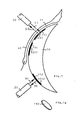
- Fig.1: Eine erste Ausführung der Erfindung
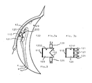
- Fig.2: Eine zweite Ausführung der Erfindung
- Fig.3: Eine AbwandLung der Erfindung
- In Fig.1 sind in der am AugenLid anliegenden FLäche 11 eines Trägerkörpers 10 Vertiefungen 1010,1011,.. angeordnet, deren Rückseite reflektierend ausgebildet sein kann, und in die Optoden 110,111.. eingelegt sind. SoLche Optoden bestehen beispielsweise aus KuststoffoLien, Fig.1a, in denen Indikatoren angeordnet sind, die bei BestrahLung mit Licht einer bestimmten, vom Indikator abhängigen Wellenlänge Fluoreszenzlicht erzeugen. Das FLuoreszenzLicht oder "MessLicht" 30 weist eine andere Farbe auf aLs das Prüflicht 31. Dieses Messlicht 30, das in Fig.1 ebenso wie das Prüflicht 31 von einem LichtLeiter 20, der mehrer Fasern aufweisen kann, transportiert wird, kann Leicht durch bekannte optische MitteL vom MessLicht getrennt und nachgewiesen werden. Die dazu erforderliche Anordnung ist aus der Technik bekannt und nicht eigens gezeichnet.
- Der Indikator, der dieses Fluorszenzlicht erzeugt, wird seinerseits von einer zu messenden PartikeLart, beispielsweise von Sauerstoff, der von der InnenoberfLäche des AugenLids 40 ausgeht und der im DiffusionsgLeichgewicht mit dem kapillaren Sauerstoff in der SchLeimhaut des AugenLids steht, beeinfLusst und ändert seine Fluoreszenzlichtabgabe entsprechend der Konzentration des Sauerstoffes.
- Die Messung für p02 und pC02 erfolgt durch das AugenLid mittels der Optoden 110, 111.., damit keine VerfäLschungen durch die Atmosphäre erfoLgen. Das ist deshalb mögLich, weil das FLuoreszenzLicht des Indikators gut aus der reflektierten StrahLung ausgefiLtert werden kann.
- Weiterhin können die Optoden ohne weiteres aus biokompatibLen Stoffen hergestellt werden, sodass weder toxische noch kontaminierende Vorgänge durch die Messung ausgelöst werden. Durch optische EntkoppLung der Optoden mittels reflektierender oder absorbierender Schichten kann die bei der Messung mögliche EinstrahLung in die Retina ausgeschaltet werden.
- Die derart gemessene Intensität des Fluoreszenzlichtes wird mit einem Korrekturfaktor multipliziert, der durch Eichung ermittelt ist. Die Abweichung der PartiaLdrucke von den arterieLLen Drucken kann durch eine weitere Korrektur eliminiert werden.
- Für besondere Messaufgaben kann eine Optode 112 auch im offenen LidspaLt angeordnet sein. Weiterhin können mehrere Optoden, insbesondere zur simultanen Messung mehrere PartikeLarten oder physikalischer Parameter, wie beispielsweise der Sauerstoffkonzentration, des C02-PartiaLdruckes, des pH-Wertes, der GLucosekonzentration, der Temperatur. und dergl, auf der Vorrichtung angeordnet sein.
- Die Anordnung nach Fig.2 wird dann verwendet, wenn der p02-Wert, der pH-Wert oder der pC02-Wert bei geöffnetem Lid gemessen werden und dabei die BeLeuchtung nicht durch das AugenLid erfolgen soLL.
- Dazu ist die Vertiefung 1010 soweit am Rande des Trägerkörpers 10 angeordnet, dass das Lid 40 diese Optode permanent bedeckt. Der das PrüfLicht 31 und das MessLicht 30 transportierende Lichtleiter 20 bestrahlt eine KoppLungsfLäche 105, die die EndfLäche eines Licht Leiters 106 ist, der die StrahLung auf die Optode 110 Leitet. Dabei verläuft das Licht beispielsweise über einen SpiegeL 107 des OptodenhaLters 108
- Das sodann von der Optode ausgehende MessLicht Läuft auf dem gleichen Wege zurück.
- Die Anordnung 1100 in Fig.2a, die eine einstückige Ausführung der EinzeLteiLe: KoppLungsfLäche (105), LichtLeiter (106), Spiegel (107), OptodenhaLter (108) ist, kann beispielsweise für sich hergesteLLt und in einen mit den entsprechenden KanäLen versehenen Trägerkörper 10 eingesetzt sein.
- In Fig.3 ist eine Anordnung dargesteLLt, bei der ZuLeitungen a,b,c auf den Trägerkörper zugelasgen werden. Dadurch ist es möglich, farbig emittierende Leuchtdioden 120 und Fotoempfänger 121 im Trägerkörper anzuordnen, die über ZuLeitungen a,b gespeist und deren SignaLe über die Leitungen b,c abgenommen werden.
- Dabei können, je nach verfügbarem Raum, Anordnungen nach Fig.3a oder Fig.3b verwendet werden.
- Auch in diesem FaLL bilden die Anordnungen 1200,1210 aus Leuchtdiode 120, SpiegeL 122, Fotoempfänger 121 und OptodenhaLter 123 Baueinheiten, die in den Trägerkörper 10 eingelassen sind.
Claims (9)
gekennzeichnet
dass ein Trägerkörper (10) vorgesehen ist, der Vertiefungen (1010,1011,..) in der am Lid (40) anliegenden FLäche (11) aufweist, in denen Indikatorräume (Optoden) (110,111,..) angeordnet sind.
Applications Claiming Priority (2)
| Application Number | Priority Date | Filing Date | Title |
|---|---|---|---|
| DE19833313047 DE3313047A1 (de) | 1983-04-12 | 1983-04-12 | Anordnung zur messung von diffundierenden partikeln |
| DE3313047 | 1983-04-12 |
Publications (2)
| Publication Number | Publication Date |
|---|---|
| EP0121831A2 true EP0121831A2 (de) | 1984-10-17 |
| EP0121831A3 EP0121831A3 (de) | 1987-11-11 |
Family
ID=6196041
Family Applications (1)
| Application Number | Title | Priority Date | Filing Date |
|---|---|---|---|
| EP84103037A Withdrawn EP0121831A3 (de) | 1983-04-12 | 1984-03-20 | Anordnung zum Messen von diffundierenden Partikeln |
Country Status (4)
| Country | Link |
|---|---|
| US (1) | US4597392A (de) |
| EP (1) | EP0121831A3 (de) |
| JP (1) | JPS59207135A (de) |
| DE (1) | DE3313047A1 (de) |
Cited By (4)
| Publication number | Priority date | Publication date | Assignee | Title |
|---|---|---|---|---|
| WO1990012534A1 (en) * | 1989-04-26 | 1990-11-01 | Glynn Christopher J | Device for monitoring body functions |
| EP0567447A1 (de) * | 1992-04-23 | 1993-10-27 | AVL Medical Instruments AG | Sensoranordnung zur direkten oder indirekten Bestimmung physikalischer oder chemischer Parameter |
| US5881879A (en) * | 1997-02-07 | 1999-03-16 | Baxter International Inc. | System for preserving and delivering gas-containing solutions |
| WO1999040839A1 (fr) * | 1998-02-13 | 1999-08-19 | Centre National De La Recherche Scientifique (Cnrs) | Mesure optique d'un marqueur fluorescent dans les bronches |
Families Citing this family (33)
| Publication number | Priority date | Publication date | Assignee | Title |
|---|---|---|---|---|
| CA1305873C (en) * | 1987-05-26 | 1992-08-04 | Howel Gwynne Giles | Method and means for detecting alcohol levels in humans |
| AT388248B (de) * | 1987-07-20 | 1989-05-26 | Avl Verbrennungskraft Messtech | Deckschicht, vorzugsweise zur probenseitigen anbringung an optischen ionensensoren |
| EP0312293A3 (de) * | 1987-10-16 | 1990-03-14 | O.C.T. Optical Chemical Technologies Limited | Fühlervorrichtung für die Analyse |
| US4922919A (en) * | 1988-03-22 | 1990-05-08 | Duke University | Method for measuring ocular oxidative metabolism |
| US5452723A (en) * | 1992-07-24 | 1995-09-26 | Massachusetts Institute Of Technology | Calibrated spectrographic imaging |
| US5560356A (en) * | 1994-02-23 | 1996-10-01 | Vitrophage, Inc. | Diagnostic system and method using an implanted reflective device |
| US6108576A (en) * | 1996-03-18 | 2000-08-22 | The Research Foundation Of City College Of New York | Time-resolved diffusion tomographic 2D and 3D imaging in highly scattering turbid media |
| US6120460A (en) * | 1996-09-04 | 2000-09-19 | Abreu; Marcio Marc | Method and apparatus for signal acquisition, processing and transmission for evaluation of bodily functions |
| US6544193B2 (en) * | 1996-09-04 | 2003-04-08 | Marcio Marc Abreu | Noninvasive measurement of chemical substances |
| HU226183B1 (en) | 1999-08-26 | 2008-06-30 | Novartis Ag | Ophthalmic lens and sensor system for measuring the concentration of an analyte in an ocular fluid |
| GB0016841D0 (en) * | 2000-07-07 | 2000-08-30 | Stanley Christopher J | Optical device for measurement of analytes in tears |
| US20040152963A1 (en) * | 2001-04-27 | 2004-08-05 | March Wayne Front | Apparatus for measuring blood glucose concentrations |
| US6650915B2 (en) * | 2001-09-13 | 2003-11-18 | Fovioptics, Inc. | Non-invasive measurement of blood analytes using photodynamics |
| US20050010091A1 (en) * | 2003-06-10 | 2005-01-13 | Woods Joe W. | Non-invasive measurement of blood glucose using retinal imaging |
| KR101205935B1 (ko) * | 2002-04-22 | 2012-11-28 | 마시오 마크 아우렐리오 마틴스 애브리우 | 뇌 온도 터널의 단부에 있는 피부에 배치하기 위한 지지 구조체 |
| US9848815B2 (en) | 2002-04-22 | 2017-12-26 | Geelux Holdings, Ltd. | Apparatus and method for measuring biologic parameters |
| US8849379B2 (en) * | 2002-04-22 | 2014-09-30 | Geelux Holdings, Ltd. | Apparatus and method for measuring biologic parameters |
| US8328420B2 (en) | 2003-04-22 | 2012-12-11 | Marcio Marc Abreu | Apparatus and method for measuring biologic parameters |
| US6895264B2 (en) * | 2002-08-26 | 2005-05-17 | Fovioptics Inc. | Non-invasive psychophysical measurement of glucose using photodynamics |
| US10227063B2 (en) | 2004-02-26 | 2019-03-12 | Geelux Holdings, Ltd. | Method and apparatus for biological evaluation |
| KR20060044058A (ko) * | 2004-11-11 | 2006-05-16 | 삼성전자주식회사 | 투과반사를 이용한 혈중성분 측정 장치 및 방법 |
| CA2627278A1 (en) | 2005-10-24 | 2007-05-03 | Marcio Marc Abreu | Apparatus and method for measuring biologic parameters |
| US8971978B2 (en) | 2012-08-21 | 2015-03-03 | Google Inc. | Contact lens with integrated pulse oximeter |
| EP4079242B1 (de) * | 2013-03-19 | 2025-10-08 | Surgisense Corporation | Vorrichtung, systeme und verfahren zur bestimmung der sauerstoffanreicherung von gewebe |
| WO2015054681A1 (en) | 2013-10-11 | 2015-04-16 | Marcio Marc Abreu | Method and apparatus for biological evaluation |
| WO2015106180A1 (en) | 2014-01-10 | 2015-07-16 | Marcio Marc Abreu | Devices to monitor and provide treatment at an abreu brain tunnel |
| CN106102566A (zh) * | 2014-01-10 | 2016-11-09 | 马尔西奥·马克·阿布雷乌 | 用于测量abreu脑热通道的红外输出的装置 |
| WO2015112776A2 (en) | 2014-01-22 | 2015-07-30 | Marcio Marc Abreu | Devices configured to provide treatment at an abreu brain thermal tunnel |
| WO2015154094A1 (en) | 2014-04-05 | 2015-10-08 | Zand Jason M | Apparatus, systems, and methods for mapping of tissue oxygenation |
| WO2016054079A1 (en) | 2014-09-29 | 2016-04-07 | Zyomed Corp. | Systems and methods for blood glucose and other analyte detection and measurement using collision computing |
| JP2018512915A (ja) | 2015-03-10 | 2018-05-24 | マーシオ マーク アブリュー | Abtt終端の温度を測定するためのデバイス、装置、システム、及び方法 |
| US9554738B1 (en) | 2016-03-30 | 2017-01-31 | Zyomed Corp. | Spectroscopic tomography systems and methods for noninvasive detection and measurement of analytes using collision computing |
| WO2018187693A1 (en) | 2017-04-06 | 2018-10-11 | TearDX LLC | Ocular devices and methods for the employment thereof |
Family Cites Families (17)
| Publication number | Priority date | Publication date | Assignee | Title |
|---|---|---|---|---|
| US3769963A (en) * | 1972-03-31 | 1973-11-06 | L Goldman | Instrument for performing laser micro-surgery and diagnostic transillumination of living human tissue |
| US3893444A (en) * | 1972-07-20 | 1975-07-08 | Univ California | Non-invasively measuring arterial oxygen tension |
| US3769961A (en) * | 1972-07-20 | 1973-11-06 | I Fatt | Conjunctival device |
| USRE29703E (en) * | 1974-01-17 | 1978-07-18 | The Regents Of The University Of California | Non-invasively measuring arterial oxygen tension |
| US4014321A (en) * | 1974-11-25 | 1977-03-29 | March Wayne F | Non-invasive glucose sensor system |
| US4041932A (en) * | 1975-02-06 | 1977-08-16 | Fostick Moshe A | Method for monitoring blood gas tension and pH from outside the body |
| DE2508637C3 (de) * | 1975-02-28 | 1979-11-22 | Max-Planck-Gesellschaft Zur Foerderung Der Wissenschaften E.V., 3400 Goettingen | Anordnung zur optischen Messung von Blutgasen |
| JPS5834129B2 (ja) * | 1975-10-29 | 1983-07-25 | ミノルタ株式会社 | ガンテイミヤクハケイ |
| DE2632710C3 (de) * | 1976-07-21 | 1979-11-08 | Max-Planck-Gesellschaft Zur Foerderung Der Wissenschaften E.V., 3400 Goettingen | Anordnung zur optischen Messung von Stoffkonzentrationen |
| CA1089252A (en) * | 1976-10-18 | 1980-11-11 | John M. Sperinde | Optical catheter not requiring individual calibration |
| DE2833356A1 (de) * | 1978-07-29 | 1980-02-14 | Max Planck Gesellschaft | Verfahren zur optischen messung von stoffkonzentrationen |
| US4344438A (en) * | 1978-08-02 | 1982-08-17 | The United States Of America As Represented By The Department Of Health, Education And Welfare | Optical sensor of plasma constituents |
| FR2443233A1 (fr) * | 1978-12-04 | 1980-07-04 | Essilor Int | Verre de contact pour l'electroretinographie |
| DE2915367A1 (de) * | 1979-04-14 | 1980-10-30 | Max Planck Gesellschaft | Optische indikatormessung |
| DE2927814C2 (de) * | 1979-07-10 | 1982-08-05 | Hellige Gmbh, 7800 Freiburg | Verfahren und Vorrichtung zur transkutanen photometrischen Bestimmung der Konzentration von Bestandteilen im Blut |
| US4350163A (en) * | 1980-05-29 | 1982-09-21 | Ford Jr Norman C | Method and apparatus for analyzing contaminants in aqueous humor |
| US4454643A (en) * | 1981-04-20 | 1984-06-19 | Thoratec Laboratories Corporation | Combination membraning tool, package and calibration unit for eyelid sensor or the like |
-
1983
- 1983-04-12 DE DE19833313047 patent/DE3313047A1/de not_active Ceased
-
1984
- 1984-03-20 EP EP84103037A patent/EP0121831A3/de not_active Withdrawn
- 1984-04-02 US US06/597,105 patent/US4597392A/en not_active Expired - Lifetime
- 1984-04-12 JP JP59071936A patent/JPS59207135A/ja active Granted
Cited By (8)
| Publication number | Priority date | Publication date | Assignee | Title |
|---|---|---|---|---|
| WO1990012534A1 (en) * | 1989-04-26 | 1990-11-01 | Glynn Christopher J | Device for monitoring body functions |
| GB2248297A (en) * | 1989-04-26 | 1992-04-01 | Glynn Christopher J | Device for use in real-time monitoring of human or animal bodily functions |
| GB2248297B (en) * | 1989-04-26 | 1993-11-24 | Glynn Christopher J | Device for use in real-time monitoring of human or animal bodily functions. |
| EP0686372A1 (de) * | 1989-04-26 | 1995-12-13 | GLYNN, Christopher James | Vorrichtung zum Überwachen von Körperfunktionen |
| EP0567447A1 (de) * | 1992-04-23 | 1993-10-27 | AVL Medical Instruments AG | Sensoranordnung zur direkten oder indirekten Bestimmung physikalischer oder chemischer Parameter |
| US5881879A (en) * | 1997-02-07 | 1999-03-16 | Baxter International Inc. | System for preserving and delivering gas-containing solutions |
| WO1999040839A1 (fr) * | 1998-02-13 | 1999-08-19 | Centre National De La Recherche Scientifique (Cnrs) | Mesure optique d'un marqueur fluorescent dans les bronches |
| FR2774887A1 (fr) * | 1998-02-13 | 1999-08-20 | Centre Nat Rech Scient | Capteur optique sur substrat de silicium et application a la mesure in situ d'un marqueur fluorescent dans les petites bronches |
Also Published As
| Publication number | Publication date |
|---|---|
| EP0121831A3 (de) | 1987-11-11 |
| JPH0433456B2 (de) | 1992-06-03 |
| DE3313047A1 (de) | 1984-10-18 |
| JPS59207135A (ja) | 1984-11-24 |
| US4597392A (en) | 1986-07-01 |
Similar Documents
| Publication | Publication Date | Title |
|---|---|---|
| DE3313047A1 (de) | Anordnung zur messung von diffundierenden partikeln | |
| DE602004011471T2 (de) | Optoelektronische Vorrichtung zum schnellen diagnostischen Assay | |
| DE2851138C2 (de) | ||
| AT391949B (de) | Die optische messung von stoffkonzentrationen | |
| EP0093927B1 (de) | Gerät zur Spektrenmessung in der Blutbahn | |
| DE69408976T2 (de) | Glukose fluoreszenz monitor und verfahren | |
| DE2508637C3 (de) | Anordnung zur optischen Messung von Blutgasen | |
| DE2632556C2 (de) | Lichtzuführung für eine Vorrichtung zur optischen Messung von Stoffkonzentrationen | |
| DE69219767T2 (de) | Verfahren und vorrichtung zur überwachung der glukosekonzentration | |
| DE102007003341B4 (de) | Okularsensor und Messsystem zum Nachweis eines Analyten in einer Augenflüssigkeit | |
| CH665345A5 (de) | Sonde zum bestimmen des sauerstoffpartialdruckes. | |
| EP2317909B1 (de) | Medizinisches system mit kompaktem barcodeleser für verbrauchsartikel | |
| DE3528369A1 (de) | Spektralphotometer und spektralphotometrisches verfahren | |
| EP0030610B1 (de) | Verfahren und Vorrichtung zur quantitativen Bestimmung optisch aktiver Substanzen | |
| DE2215984B2 (de) | Katheter | |
| DE3432157A1 (de) | Bildaufnahmevorrichtung fuer ein endoskop | |
| EP0555645A1 (de) | Einrichtung zum Erkennen von Karies an Zähnen | |
| DE112019004578T5 (de) | Optischer verteilungssteckverbinder und endoskopsystem | |
| EP0049905A1 (de) | Einrichtung zur Messung der Farbe des Zahnfleisches | |
| DE602004006396T2 (de) | Analyse einer zusammenstellung mit beobachtung | |
| DE69731327T2 (de) | Gerät und Verfahren zur Feststellung der Urinfarbe | |
| DE102017001484A1 (de) | Verfahren und Anordnung zum Kalibrieren von Vorrichtungen zur Erkennung von Blut oder Blutbestandteilen in einer Flüssigkeit | |
| DE3825352A1 (de) | Verfahren und vorrichtung zur bestimmung von lokalen farbstoff-konzentrationen und von streuparametern in tierischen und menschlichen geweben | |
| DE3243919A1 (de) | Kolorimetrieverfahren und -vorrichtung | |
| DE2204433A1 (de) | Mit einem Katheter verbundenes Mehrfach-Photometer |
Legal Events
| Date | Code | Title | Description |
|---|---|---|---|
| PUAI | Public reference made under article 153(3) epc to a published international application that has entered the european phase |
Free format text: ORIGINAL CODE: 0009012 |
|
| AK | Designated contracting states |
Designated state(s): AT CH FR GB IT LI LU NL SE |
|
| PUAL | Search report despatched |
Free format text: ORIGINAL CODE: 0009013 |
|
| AK | Designated contracting states |
Kind code of ref document: A3 Designated state(s): AT CH FR GB IT LI LU NL SE |
|
| 17P | Request for examination filed |
Effective date: 19880406 |
|
| STAA | Information on the status of an ep patent application or granted ep patent |
Free format text: STATUS: THE APPLICATION IS DEEMED TO BE WITHDRAWN |
|
| 18D | Application deemed to be withdrawn |
Effective date: 19900504 |
|
| RIN1 | Information on inventor provided before grant (corrected) |
Inventor name: LUEBBERS, DIETRICH WERNER, PROF. DR. Inventor name: OPITZ, NORBERT, DR. DIPL.-PHYS. |