EP0122111A2 - Système d'emmagasinage pour machine de vente - Google Patents
Système d'emmagasinage pour machine de vente Download PDFInfo
- Publication number
- EP0122111A2 EP0122111A2 EP84302295A EP84302295A EP0122111A2 EP 0122111 A2 EP0122111 A2 EP 0122111A2 EP 84302295 A EP84302295 A EP 84302295A EP 84302295 A EP84302295 A EP 84302295A EP 0122111 A2 EP0122111 A2 EP 0122111A2
- Authority
- EP
- European Patent Office
- Prior art keywords
- rack
- container
- ramp
- disposed
- door
- Prior art date
- Legal status (The legal status is an assumption and is not a legal conclusion. Google has not performed a legal analysis and makes no representation as to the accuracy of the status listed.)
- Withdrawn
Links
- 230000000295 complement effect Effects 0.000 abstract description 3
- 230000000712 assembly Effects 0.000 description 5
- 238000000429 assembly Methods 0.000 description 5
- 235000013361 beverage Nutrition 0.000 description 4
- WYTGDNHDOZPMIW-RCBQFDQVSA-N alstonine Natural products C1=CC2=C3C=CC=CC3=NC2=C2N1C[C@H]1[C@H](C)OC=C(C(=O)OC)[C@H]1C2 WYTGDNHDOZPMIW-RCBQFDQVSA-N 0.000 description 3
- 238000009924 canning Methods 0.000 description 1
- 238000010276 construction Methods 0.000 description 1
- 230000007812 deficiency Effects 0.000 description 1
- 230000000994 depressogenic effect Effects 0.000 description 1
- 230000005484 gravity Effects 0.000 description 1
- 238000009434 installation Methods 0.000 description 1
- 239000002184 metal Substances 0.000 description 1
- 239000002991 molded plastic Substances 0.000 description 1
- 238000010079 rubber tapping Methods 0.000 description 1
Images


Classifications
-
- G—PHYSICS
- G07—CHECKING-DEVICES
- G07F—COIN-FREED OR LIKE APPARATUS
- G07F11/00—Coin-freed apparatus for dispensing, or the like, discrete articles
- G07F11/02—Coin-freed apparatus for dispensing, or the like, discrete articles from non-movable magazines
- G07F11/34—Coin-freed apparatus for dispensing, or the like, discrete articles from non-movable magazines in which the magazines are of zig-zag form
Definitions
- This invention relates generally to vending machines and particularly to a rack assembly for storing beverage containers within the vending machine.
- vending machines for dispensing articles such as beverage container cans are large free-standing units which dispense one article from a plurality of serpentine stacks into a single open dispensing compartment.
- the stacks of such units are generally of wire frame and are particularly complicated and therefore expensive because they are formed from welded wire or metal as individual units.
- the present rack assembly overcomes these and other deficiencies.
- the present rack assembly is particularly adapted for use within a relatively light weight small machine that is wall mounted or can stand on a counter top.
- the vending machine provides a plurality of compartments and is adapted to deliver one container from each compartment as desired.
- This rack assembly provides first and second interconnected molded rack portions.
- the first rack portion includes a pair of upright frame members and a plurality of ramp means disposed in spaced vertical relation, each having an inwardly projecting downwardly inclined upper face.
- the second rack portion also includes a pair of upright frame members and a plurality of ramp means disposed in spaced vertical relation each having an inwardly projecting downwardly inclined upper face.
- the rack portions are connected in face-to-face relation with the ramp means of one rack being disposed in overlapping, staggered relation to the ramp means of the other rack to define a container-receiving compartment providing a serpentine path for the containers from an entry opening at the upper end to a dispensing opening at the lower end.
- the first rack portion includes a lower ramp means having a container-engageable cradle which selectively permits and precludes forward movement of the containers into the dispensing area.
- the cradle includes a container-carrying bearing portion disposed forwardly of the cradle pivot axis and a container-engageable stop portion disposed rearwardly of the pivot axis, said cradle including biasing means tending to move the stop portion out of container engagement when the bearing portion is relieved of container load, said stop portion tending to move into container engagement when the cradle bearing portion is under container load.
- first and second rack portions include interengageable contact faces and the ramp means of each rack extends beyond its associated contact face and into the other rack portion.
- the second rack portion includes an upper guide platform disposed between the upright frame members and above the rack members, said rack portion being spaced from the first rack portion to provide the container entry opening.
- first rack portion and the second rack portion each include at least one intermediate frame member to provide a plurality of container-receiving compartments each having a plurality of ramp means, the ramp' means of the first and second rack portions being disposed in overlapped, staggered relation.
- the rack portion frame members include outwardly extending container retaining means disposed in vertically spaced relation between the ramp means for precluding sideways movement of the containers.
- the rack portions include outwardly disposed generally vertical container retainer means disposed in spaced vertical relation between the ramp means for precluding outward movement of the containers.
- a face plate is provided between the lower ends of the first and second rack portions, said face plate including a door opening.
- a door is hinged to the face plate below the opening, said door having a bottom member and a side member defining a container-receiving bin, the door being selectively movable between an open and closed position.
- Stop means is provided, actuated by the door, to selectively engage a container on the lower ramp while the door is in the open position thereby precluding passage of said container into the bin, said stop means being movable into a second position when the door is in the closed position to permit passage of the container into the bin.
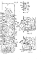
- the rack assembly 10 which is mounted in a cabinet 12, providing a housing, includes interconnected first and second molded plastic rack portions 14 and 16 disposed in face to face relation.
- first and second rack portions When assembled, as shown in FIG. 1, the first and second rack portions define three substantially similar vertical compartments 1, 2 and 3 adapted to receive articles which in the embodiment shown are cans or similar beverage containers indicated by C.
- the first rack portion 14 which is best understood by reference to FIGS. 2-4, 6 and 7, includes opposed elongate side frame members 18 and a pair of elongate intermediate frame members 20 having a generally U-shaped configuration providing leg portions 22 and a bight portion 24.
- the side members 18 include a plurality of outstanding arms 26-36 and as shown in FIG. 2 the intermediate frame members 20 include a plurality of opposed pairs of outstanding arms 40-50 attached to the intermediate frame legs 22 and being generally in transverse register with the outstanding arms of the side frame members 18.
- the first rack portion 14 also includes upper cross frame members 64 and lower base frame members 66, the base frame members 66 having projecting cantilever arms 68 which provide a connection to front plate, as will be described, to which the first and second portions 14 and 16 are connected.
- the first rack portion 14 includes a plurality of upper, lower and intermediate generally horizontal ramp means 70, 80, 81 and 90.
- the upper ramp means 70 includes transversely aligned opposed pairs of ramp Oembers 72.
- each of the ramp members includes a nose portion 74, attached to an associated upright frame members 18 or 20, and upper and lower bracing members 76 and 78 connecting the nose portion 74 to the upper cross members 64 and a cross member 52 respectively.
- the nose portion 74 projects forwardly beyond the generally planar connection surface of the rack assembly indicated by P said connection contact surfaces defining the inner portion of the frame members.
- the intermediate ramp assemblies 80 and 81 include opposing pairs of ramp members 82 attached to associated frame members, each having a nose portion 84 and upper and lower bracing elements 86 and 88, the nose portions 84 of upper ramp assembly 80 being connected to cross members 54 and 56 respectively by said bracing elements and the nose portions 84 of ramp assembly 81 being connected to cross members 58 and 60 respectively.
- the lower ramp assembly 90 includes opposed pairs of ramp members 92, attached to associate frame members, each having a nose portion 94 and upper bracing elements 96 attached to cross members 62.
- the upper cross member 64 and the cross members 52 are interconnected by diagonal bracing members 98 to provide the rack portion 14 with additional stiffness, and brackets 100 are provided by which the rack portion 14 is attached to the cabinet 12.
- cross members 52-54 are interconnected by a plurality of vertical members 102; cross members 56 and 58 are interconnected by vertical members 104 and a center panel portion 104a, and cross members 60 and 62 are interconnected by vertical members 106.
- the vertical members 102, 104 and 106 define the rear face of the rack portion 14 and provide a retaining means for the container C precluding outward movement thereof.
- the first rack side members 118 are provided with outstanding flanges 101, 103 and 105 (FIG. 3) and the corresponding intermediate member legs 22 are provided with similar flanges 107, 109 and 111 (FIG. 2) to perform the same function, said flanges providing container end retaining means precluding sideways movement of said containers.
- the lower ramp assembly 90 includes opposed pairs of stub axles 108 (FIG. 4) which are attached to nose portions 94 and provide a mounting for cradle members 300 which are provided at the lower end. of each of the rack compartments 1, 2 and 3 as shown in FIG. 1 which will be described in greater detail below.
- the first rack portion side members 18 include a plurality of apertured lugs 112 and the intermediate members 20 include a plurality of apertures 114 by which the first and second rack portions 14 and 16 are connected as by fasteners 116.
- the second rack portion is provided with corresponding blind holes.
- the second rack portion 16 has a structural arrangement of parts which is generally complementary to the first rack portion 14 and is best understood by reference to FIGS. 2, 3 and 5 and FIGS. 8 and 9.
- the second rack portion 16 includes opposed elongate side frame members 118 and elongate intermediate frame members 120 having a generally U-shaped configuration providing leg portions 122 and a bight portion 124.
- the side frame members 118 include a plurality of outstanding arms 126 - 136 and, as shown in FIG. 2, the intermediate frame members 120 include a plurality of opposed pair of outstanding arms 140-150 attached to intermediate frame legs 122 and being generally in register with the outstanding arms of the side frame members 118.
- the second rack portion 16 also includes upper cross frame members 164 and lower cross frame members 166.
- the upper frame member 164 includes a guide assembly 170 which provides a plurality of guide platform members 172, said platform members, as shown in FIG. 2, being spaced from the face of the first rack portion 14 and cooperating with the first rack portion 14 to define an entry opening for associated container compartments 1, 2 and 3.
- the second rack portion 16 also includes a plurality of intermediate and lower generally horizontal ramp assemblies 180, 181 and 190.
- the intermediate ramp assemblies 180 and 181 each includes opposed pairs of ramp members 182 having a nose portion 184 attached to adjacent side frame members 118 or intermediate side frame member 120 and upper and lower bracing elements 186 and 188 connecting the nose portion 184 to cross members 152 and 154 respectively or 156 and 158 respectively.
- the lower ramp assembly 190 includes opposed pairs of ramp elements 192, attached to associated frame members, each of which is provided with a nose portion 194 and upper bracing elements 196 attached to cross members 160.
- the nose portions project forwardly beyond the general planar surface of the rack portion 16 indicated by P which defines the inner portions of the frame members and the upper platform and said nose portions each includes an upper container-receiving inclined face.
- cross members 154 and 156 are interconnected by vertical members 204 and a center panel portion 204a.
- the upper cross member 164 is connected to cross members 152 by vertical members 202 and the cross members 160 are connected to cross member 158 by vertical members 206.
- the vertical members 202, 204 and 206 define the rear face of the rack portion 14 and provide a retaining means for the containers C.
- the second rack side frame members 118 include outstanding flanges 201, 203 and 205 while the corresponding intermediate frame member 120 include corresponding outstanding flanges 207, 209 and 211 said flanges providing container end retraining means.
- the second rack portion side members 118 include a plurality of lugs 222 having blind holes and the intermediate members 120 include a plurality of blind holes 224. Because of this structural arrangement of parts the two rack portions are readily connected together in face to face engagement by means of fasteners l16 as shown in FIG . 3.
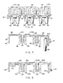
- each cradle member 300 is best understood by reference to FIGS. 1, 2 and 4 each cradle member including apertured side arms 302 by which said members 300 are pivotally mounted to stub axles 108.
- the side arms 302 are connected at the forward end by a cross bar 304 and at the rearward end by an upwardly extending cross bar 306 having a beveled stop face 308.
- a tension spring 310 is connected between the rear cross bar 306 and the rack cross member 66 tending to bias the front end of the side arms upwardly.
- the front end of the cradle member 300 is depressed by the weight of a container C2 such that the rear cross bar 306 projects upwardly into engagement with the container C3 next in line.
- the cradle member 300 facilitates the dispensing of the containers which will be described in greater detail below.
- a vending machine having a dispensing means of this general type is disclosed in our copending applications Serial No. 451,454 filed December 10, 1982 and Serial No. 451,035 filed December 20, 1982 disclosures of which are hereby incorporated herein by reference.
- the container dispensing means 318 for the rack assembly 10 is best shown in FIGS. 2, 10 and 11.
- the dispensing assembly includes a front plate 320 attached between the cantilever arms 68 of the first rack portion 14 and the cross member 160 of the second rack portions as by fasteners, not shown.
- the plate 320 includes a plurality, a total of three in the embodiment disclosed, of door openings 322 said openings being disposed in spaced horizontal alignment each opening being provided with a door 324 and communicating with one of the compartments 1, 2 and 3.
- Each door 324 is mounted to the front plate 320 below its associated door opening respectively by a hinge connection 326 and is movable selectively from a closed position to an open position.
- Each door includes a bottom plate providing a shelf 328 extending inwardly of its associated opening 322 and sidewalls 330 which cooperate with the rear face of the door to provide a bin for holding the cylindrical container to be dispensed.
- the rack assembly 10 provides serpentine feed means adapted to retain the containers C, and to feed them under gravity in a controlled manner, in sequence, one by one into the bin of the door 324.
- a control means generally indicated by 332 is provided adjacent each opening 322.
- the control means is movable from a first position (FIGS. 2 and 11) to a second position (FIG. 10).
- first position when the door 324 is fully closed, the disposition of the control means allows transfer of a container from the lower ramp assembly 90 to the bin.
- second position when the door 324 is moved into its open position, the disposition of the control means blocks transfer of a container seated on the ramp assembly 90.
- control means 332 includes an upper cradle 334 having a transverse pivot rod 336, mounted between laterally spaced brackets 338 attached to the rear face of the front plate 320.
- the cradle 334 also includes a forwardly disposed transverse rod 340 extending between the feed means and the door bin, and adapted to engage and hold the container C seated on the ramp assembly 90 and preclude transfer of the container to the door bin until the door 324 is fully closed.
- a tension spring 339 Connected to a rearwardly disposed rod 337 of the upper cradle 334 is a tension spring 339 , constituting a resilient means, that tends to pivot the cradle 334 and urge the container-engageable transverse rod 340 into the path of the container to preclude transfer from the ramp assembly 90.
- the cradle 334 includes an actuating rod 342 disposed between the pivot rod 336 and rod 340.
- An operating means for the cradle 332 is provided which selectively interconnects the cradle 332 and the door 324 to allow loading of the door bin when the door is in its closed position, and to preclude loading of the bin when the door 324 is moved from its closed position.
- the operating means in the embodiment shown is provided by the generally quadrant-shaped sidewall 330 of the door which includes a contoured margin 344.
- the cradle actuating rod 342 is selectively engageable with and seats on the contoured margin 344 as is illustrated in FIG.
- the rack assembly 10 mounted in the cabinet 12 as shown in FIG. 2 provides a means of storing beverage containers and the like in a plurality of compartments, three in the embodiment shown, said compartments being substantially identical to each other.
- the rack assembly 10 is formed from complementary rack portions 14 and 16 which are connected together in face to face relation on a plane generally indicated by P in FIG. 2, the connection means being provided by fasteners such as self tapping screws 116 shown in FIG. 3.
- the front plate 320 is connected between the lower ends of the rack portions 14 and 16 and the rack assembly 10 as a whole is mounted within the cabinet 12 by means of cooperating bracket elements 100 and 101 provided on the rack assembly and the cabinet respectively.
- the compartments 1, 2 and 3 are generally serpentine in configuration and include by an upper platform assembly 170 on the second rack portion 16 defining an entry opening and a plurality of alternating ramp assemblies 70, 80, 81 and 90 on the first rack portion and 180, 181 and 190 on the second rack portion said assemblies providing inwardly projecting downwardly inclined upper container-receiving faces.
- the side frame members 18 and 118 of both rack portions and the intermediate frame members 20 and 120 of both rack portion are flanged to preclude sideways movement of the containers within the compartment.
- vertical retaining members 104, 106 and 108 on the first rack portion and 204, 206 and 208 on the second rack portion provide outer retaining means.
- the latticework construction thus formed provides a relatively lightweight rack assembly easily circulated by cool air within the cabinet and providing lattice work openings which are sufficiently smaller than the smallest container dimension to preclude inadvertent outward movement of the containers from the rack.
- the rack can easily be filled from the upper end by an operator by simply inserting containers within the upper end of each compartment and allowing them to roll in a serpentine path down the ramp members to the lower end of the rack assembly.
- the first container Cl is received within the bin of the door 324.
- the second container C2 comes to rest against the first container Cl and, because of its weight, moves the lower cradle stop member upwardly into engagement with the third container C3 thereby spacing it from the container C2 and transferring its weight to the cradle 300.
- the remaining containers C4, C5 etc. rest upon each other so that even when the rack assembly is filled only the weight of containers Cl and C2 bears against the door structure.
- the door 322 When it is desired to dispense a container from the rack assembly the door 322 is opened. Because of the contoured margin of the door sidewall 330, the transverse rod 340 of the upper cradle 334 is moved downwardly as shown in FIG. 10 to engage and preclude further movement of the container C2. When the door is closed the upper cradle actuating rod 342 is moved upwardly under the canning action of the sidewall so that when the door is in the closed position the transverse rod is sufficiently high relative to the height of container C2 so that, as shown in FIG. 11, container C2 moves from the lower ramp assembly 90 into the bin.
- the rear end of said cradle moves downwardly permitting travel of the container C3 down the ramp assembly 90 and into engagement with the container C2.
- the weight of the container C3 on the front end of the cradle 300 moves the rear end of the cradle upwardly and into engagement with the container C4 resulting in the disposition of parts shown in FIG. 2 but with containers C2, C3 and C4 respectively replacing containers Cl, C2 and C3.
- the rack assembly is in condition for dispensing the next container.
Landscapes
- Physics & Mathematics (AREA)
- General Physics & Mathematics (AREA)
- Vending Machines For Individual Products (AREA)
- Vehicle Cleaning, Maintenance, Repair, Refitting, And Outriggers (AREA)
- Fittings On The Vehicle Exterior For Carrying Loads, And Devices For Holding Or Mounting Articles (AREA)
- Handcart (AREA)
- Medicines Containing Plant Substances (AREA)
- Control Of Vending Devices And Auxiliary Devices For Vending Devices (AREA)
- Display Devices Of Pinball Game Machines (AREA)
Applications Claiming Priority (2)
| Application Number | Priority Date | Filing Date | Title |
|---|---|---|---|
| US06/482,729 US4586633A (en) | 1983-04-07 | 1983-04-07 | Vending machine storage rack assembly |
| US482729 | 1983-04-07 |
Publications (2)
| Publication Number | Publication Date |
|---|---|
| EP0122111A2 true EP0122111A2 (fr) | 1984-10-17 |
| EP0122111A3 EP0122111A3 (fr) | 1986-04-23 |
Family
ID=23917205
Family Applications (1)
| Application Number | Title | Priority Date | Filing Date |
|---|---|---|---|
| EP84302295A Withdrawn EP0122111A3 (fr) | 1983-04-07 | 1984-04-04 | Système d'emmagasinage pour machine de vente |
Country Status (7)
| Country | Link |
|---|---|
| US (1) | US4586633A (fr) |
| EP (1) | EP0122111A3 (fr) |
| JP (1) | JPS59197992A (fr) |
| AU (2) | AU2545684A (fr) |
| CA (1) | CA1223846A (fr) |
| DK (1) | DK176684A (fr) |
| NO (1) | NO841204L (fr) |
Families Citing this family (19)
| Publication number | Priority date | Publication date | Assignee | Title |
|---|---|---|---|---|
| US4823983A (en) * | 1987-10-06 | 1989-04-25 | The Coca-Cola Company | Increased column/selectivity vender |
| JP2549687Y2 (ja) * | 1991-10-17 | 1997-09-30 | サンデン株式会社 | サ−ペンタイン式自動販売機の商品収納器 |
| US5368190A (en) * | 1992-03-30 | 1994-11-29 | Hieb; Larry E. | Apparatus for vending work objects |
| US6234345B1 (en) * | 1999-03-03 | 2001-05-22 | The Coca-Cola Company | Transportation vending machine |
| US6247611B1 (en) | 1999-10-15 | 2001-06-19 | Mathew Clements | Flat packet vending machine with removable cartridge |
| TW552422B (en) * | 2000-12-13 | 2003-09-11 | Hannstar Display Corp | Display inspection apparatus and inspection arrangement method of display module |
| USD474042S1 (en) | 2001-03-17 | 2003-05-06 | Lg Electronics Inc. | Storage tray dispenser |
| JP4263126B2 (ja) * | 2003-09-10 | 2009-05-13 | 株式会社クボタ | 自動販売機の商品収納装置 |
| JP4263061B2 (ja) * | 2003-09-10 | 2009-05-13 | 株式会社クボタ | 自動販売機の商品収納装置 |
| US7980417B2 (en) * | 2004-04-30 | 2011-07-19 | Display Technologies | Theft resistant product merchandiser |
| US7140293B1 (en) * | 2005-06-08 | 2006-11-28 | Deere & Company | Single row twine box |
| US8608263B2 (en) * | 2006-01-11 | 2013-12-17 | Whirlpool Corporation | Beverage container storage and dispensing compartment for a refrigerator |
| US20090057096A1 (en) * | 2007-08-30 | 2009-03-05 | Larry Hieb | Front Panels for Vending Machines |
| CN102822875A (zh) * | 2009-09-09 | 2012-12-12 | 沃特默有限责任公司 | 用于大容量产品容器的自动售货机 |
| CN104077845A (zh) * | 2013-03-28 | 2014-10-01 | 鸿富锦精密工业(武汉)有限公司 | 自动售货机货道结构 |
| US10903637B2 (en) * | 2016-09-09 | 2021-01-26 | Optical Cable Corporation | Structures for securing broadcast cabling and connectors |
| US10498119B2 (en) * | 2016-09-09 | 2019-12-03 | Optical Cable Corporation | Structures for securing broadcast cabling and connectors |
| WO2021227637A1 (fr) * | 2020-05-15 | 2021-11-18 | 邓旭林 | Armoire combinée |
| USD991741S1 (en) * | 2021-09-03 | 2023-07-11 | Electrolux Home Products, Inc. | Air canning rack |
Family Cites Families (9)
| Publication number | Priority date | Publication date | Assignee | Title |
|---|---|---|---|---|
| US1619006A (en) * | 1925-04-21 | 1927-03-01 | Ex El Company | Coin-controlled vending machine |
| DE1050170B (fr) * | 1956-06-12 | |||
| US2956660A (en) * | 1957-10-14 | 1960-10-18 | American Can Co | Can vending machine |
| US3144113A (en) * | 1959-11-02 | 1964-08-11 | Gardner Mfg Company | Can dispenser |
| GB988136A (en) * | 1964-01-31 | 1965-04-07 | Rowntree And Company Ltd | Display stand |
| US3306688A (en) * | 1965-04-05 | 1967-02-28 | Domenico Joseph Di | Article dispensing rack |
| US3348733A (en) * | 1965-11-08 | 1967-10-24 | Vendo Co | Article dispensing apparatus having an electrically controlled article releasing assembly |
| DE2733968C3 (de) * | 1977-07-28 | 1981-05-21 | Sielaff Gmbh & Co Automatenbau Herrieden, 8801 Herrieden | Warenausgabeeinrichtung für einen Selbstverkäufer |
| US4287992A (en) * | 1978-07-11 | 1981-09-08 | Shimoda Kogyo, Ltd. | Rack structure |
-
1983
- 1983-04-07 US US06/482,729 patent/US4586633A/en not_active Expired - Fee Related
-
1984
- 1984-03-09 AU AU25456/84A patent/AU2545684A/en not_active Abandoned
- 1984-03-22 CA CA000450270A patent/CA1223846A/fr not_active Expired
- 1984-03-27 NO NO841204A patent/NO841204L/no unknown
- 1984-04-03 DK DK176684A patent/DK176684A/da not_active Application Discontinuation
- 1984-04-04 EP EP84302295A patent/EP0122111A3/fr not_active Withdrawn
- 1984-04-06 AU AU26487/84A patent/AU2648784A/en not_active Abandoned
- 1984-04-06 JP JP59067824A patent/JPS59197992A/ja active Pending
Also Published As
| Publication number | Publication date |
|---|---|
| DK176684A (da) | 1984-10-08 |
| EP0122111A3 (fr) | 1986-04-23 |
| AU2648784A (en) | 1984-10-11 |
| DK176684D0 (da) | 1984-04-03 |
| US4586633A (en) | 1986-05-06 |
| JPS59197992A (ja) | 1984-11-09 |
| CA1223846A (fr) | 1987-07-07 |
| NO841204L (no) | 1984-10-08 |
| AU2545684A (en) | 1984-10-11 |
Similar Documents
| Publication | Publication Date | Title |
|---|---|---|
| EP0122111A2 (fr) | Système d'emmagasinage pour machine de vente | |
| US4105126A (en) | Storage and dispensing rack | |
| JP3920574B2 (ja) | 商品の動揺を最小にする自動販売機 | |
| US20100320222A1 (en) | Bottle Display and Dispenser Device and Method | |
| US6012604A (en) | Article ejecting device of automatic vending machine | |
| US4913313A (en) | Dual serpentine track magazine for coin operated can vendors | |
| EP1337983B1 (fr) | Distributeur automatique | |
| KR900000323Y1 (ko) | 다양한 품목을 자동판매 할수있는 기구를 가진 자동 판매기 | |
| JP2000105856A (ja) | 自動販売機の商品収納スペース調整装置 | |
| US5368189A (en) | Vending machine for newspapers and like articles | |
| JPH10247272A (ja) | 自動販売機 | |
| JPH01250195A (ja) | 自動販売機 | |
| JPH0250519B2 (fr) | ||
| JP2559566B2 (ja) | 自動販売機の商品払出装置 | |
| US4570821A (en) | Article-dispensing assembly for a vending machine | |
| US3759593A (en) | Rack for bottles and cans | |
| US2913141A (en) | Storage shelf construction for vending machines | |
| JP2957639B2 (ja) | 自動販売機の商品搬送装置 | |
| US20030146238A1 (en) | Vending machine for dispensing cans & bottles with elevator assembly | |
| JPS6127028Y2 (fr) | ||
| JPS5930188A (ja) | 自動販売機の商品払出し装置 | |
| JP2904632B2 (ja) | 自動販売機 | |
| GB2078691A (en) | Vending Machine | |
| JPH08161625A (ja) | 自動販売機の商品収納室 | |
| JPH0751667Y2 (ja) | 自動販売機 |
Legal Events
| Date | Code | Title | Description |
|---|---|---|---|
| PUAI | Public reference made under article 153(3) epc to a published international application that has entered the european phase |
Free format text: ORIGINAL CODE: 0009012 |
|
| AK | Designated contracting states |
Designated state(s): AT BE CH DE FR GB IT LI LU NL SE |
|
| PUAL | Search report despatched |
Free format text: ORIGINAL CODE: 0009013 |
|
| AK | Designated contracting states |
Kind code of ref document: A3 Designated state(s): AT BE CH DE FR GB IT LI LU NL SE |
|
| STAA | Information on the status of an ep patent application or granted ep patent |
Free format text: STATUS: THE APPLICATION IS DEEMED TO BE WITHDRAWN |
|
| 18D | Application deemed to be withdrawn |
Effective date: 19861223 |
|
| RIN1 | Information on inventor provided before grant (corrected) |
Inventor name: DELPERCIO, MICHAEL JOHN Inventor name: HOLLAND, CHARLIE RAY |