EP0122255B1 - Systeme de ventilation et d'extraction d'air pour vehicules a moteur - Google Patents
Systeme de ventilation et d'extraction d'air pour vehicules a moteur Download PDFInfo
- Publication number
- EP0122255B1 EP0122255B1 EP82902358A EP82902358A EP0122255B1 EP 0122255 B1 EP0122255 B1 EP 0122255B1 EP 82902358 A EP82902358 A EP 82902358A EP 82902358 A EP82902358 A EP 82902358A EP 0122255 B1 EP0122255 B1 EP 0122255B1
- Authority
- EP
- European Patent Office
- Prior art keywords
- ducting
- vehicle
- air
- extraction system
- roof
- Prior art date
- Legal status (The legal status is an assumption and is not a legal conclusion. Google has not performed a legal analysis and makes no representation as to the accuracy of the status listed.)
- Expired
Links
Images


Classifications
-
- B—PERFORMING OPERATIONS; TRANSPORTING
- B60—VEHICLES IN GENERAL
- B60H—ARRANGEMENTS OF HEATING, COOLING, VENTILATING OR OTHER AIR-TREATING DEVICES SPECIALLY ADAPTED FOR PASSENGER OR GOODS SPACES OF VEHICLES
- B60H1/00—Heating, cooling or ventilating devices
- B60H1/24—Ventilating devices where the heating or cooling is irrelevant
- B60H1/247—Disposition of several air-diffusers in a vehicle for ventilation-air circulation in a vehicle cabin
-
- B—PERFORMING OPERATIONS; TRANSPORTING
- B60—VEHICLES IN GENERAL
- B60H—ARRANGEMENTS OF HEATING, COOLING, VENTILATING OR OTHER AIR-TREATING DEVICES SPECIALLY ADAPTED FOR PASSENGER OR GOODS SPACES OF VEHICLES
- B60H1/00—Heating, cooling or ventilating devices
- B60H1/00507—Details, e.g. mounting arrangements, desaeration devices
- B60H1/00557—Details of ducts or cables
- B60H1/00564—Details of ducts or cables of air ducts
-
- B—PERFORMING OPERATIONS; TRANSPORTING
- B60—VEHICLES IN GENERAL
- B60H—ARRANGEMENTS OF HEATING, COOLING, VENTILATING OR OTHER AIR-TREATING DEVICES SPECIALLY ADAPTED FOR PASSENGER OR GOODS SPACES OF VEHICLES
- B60H1/00—Heating, cooling or ventilating devices
- B60H1/24—Ventilating devices where the heating or cooling is irrelevant
- B60H1/241—Ventilating devices where the heating or cooling is irrelevant characterised by the location of ventilation devices in the vehicle
- B60H1/244—Ventilating devices where the heating or cooling is irrelevant characterised by the location of ventilation devices in the vehicle located in the rear area
-
- B—PERFORMING OPERATIONS; TRANSPORTING
- B60—VEHICLES IN GENERAL
- B60H—ARRANGEMENTS OF HEATING, COOLING, VENTILATING OR OTHER AIR-TREATING DEVICES SPECIALLY ADAPTED FOR PASSENGER OR GOODS SPACES OF VEHICLES
- B60H1/00—Heating, cooling or ventilating devices
- B60H1/24—Ventilating devices where the heating or cooling is irrelevant
- B60H1/241—Ventilating devices where the heating or cooling is irrelevant characterised by the location of ventilation devices in the vehicle
- B60H1/245—Ventilating devices where the heating or cooling is irrelevant characterised by the location of ventilation devices in the vehicle located in the roof
-
- B—PERFORMING OPERATIONS; TRANSPORTING
- B60—VEHICLES IN GENERAL
- B60H—ARRANGEMENTS OF HEATING, COOLING, VENTILATING OR OTHER AIR-TREATING DEVICES SPECIALLY ADAPTED FOR PASSENGER OR GOODS SPACES OF VEHICLES
- B60H1/00—Heating, cooling or ventilating devices
- B60H1/24—Ventilating devices where the heating or cooling is irrelevant
- B60H1/248—Air-extractors, air-evacuation from the vehicle interior
Definitions
- This invention relates to an air extraction or ventilation system for motor vehicles and is primarily concerned with a system for use in private motor cars whereby better extraction of internal air can be achieved than with known systems, especially where the vehicle is intended for use in hot climates with air conditioning or where more efficient extraction of internal air is required, for example when the occupants of the vehicle are smoking.
- GB-A-839306 discloses the use of the roof space for extraction but is concerned generally with overall ventilation by fresh air and does not solve the problem of clearing smoke from localised areas in a passenger compartment, nor does it disclose an arrangement which can be fitted to an existing vehicle.
- GB-A-516448 shows a venturi powered system, which may include a fan, but involves a complex structure not adaptable to modern vehicles of limited height. Further arrangements provided in double skin roof areas are disclosed in GB-A-361245, GB-A-390366 and GB-A-426944.
- the problem to be solved is to provide roof space ventilation giving advantages inherent therein as obtained with the prior-art known, but without requiring constructional modifications and without unduly reducing headroom within the vehicle.
- the arrangement nevertheless being able to provide high extraction rates and being independent of any ventilation already fitted and also being easily fitted to existing vehicles.
- an air ventilation or extraction system in a vehicle comprises a ducting adjacent the roof and extending longitudinally thereof within the passenger compartment, a plurality of air intake apertures communicating with the ducting and each located adjacent a seating position in the vehicle, impelling means for drawing air in through the intakes and moving same along the ducting, the rear of the ducting passing through an aperture to exhaust air externally of the passenger compartment, characterised in that the ducting comprises a moulding which is located longitudinally along the juncture between the roof and side of the vehicle, the air intake apertures being provided at spaced locations along the ducting, the rear of the ducting following the roof line down to a position behind the rear-most seats and passing through the aperture to the vehicle boot, the ducting moulding being of a resilient flexible plastics material of channel section the edges of which have means such as flanges to secure the ducting to the vehicle roof.
- the ducting thus comprises a readily attachable and possibly removable moulding which is adapted to be located longitudinally along the junction between the roof and side of the vehicle above the door frames with suitable apertures being provided for intake of air at appropriately spaced locations within the passenger compartment, close to the seating position of each person.
- An electrical fan comprising the air propelling means may be located within the ducting at a suitable point to propel air down the ducting to an exhaust which passes through the vehicle body to dispose of air either externally of the vehicle or into the boot (trunk).
- the ducting will be formed so as to be as intrusive as possible and is preferably located beneath the normal fabric finish or other head lining as used in the roof.
- the ducting may, however, be covered with suitable trim for attachment to the vehicle roof. Apertures are provided in the ducting, conveniently located close to positions of passenger seating so that adequate individual extraction of air from the location of each passenger can be obtained.
- the arrangement may be integrated with the vehicle's heating and/or air conditioning system or alternatively and preferably may be an independently operating arrangement.
- the system provides for ready conversion of existing vehicles with the only external modification required being the provision of a suitable aperture or ducting to exhaust the air externally.
- the ducting may comprise a channel shape moulding forming, in conjunction with existing parts of the vehicle structure, a duct.
- the air intakes may be consituted by perforated or louvred portions which can be made adjustable.
- a single extractor fan may be provided conveniently installed on the rear parcel shelf of a vehicle and extraction of air can be through suitable orifices into the boot (trunk) of the vehicle.
- the ducting may be positioned as required to avoid serious incursions into the head room available and is suitable particularly for compact vehicles which otherwise have insufficient space for efficient ventilation. Furthermore, the invention enables an extraction system to be fitted after main assembly of a vehicle as an optional extra if required.
- a saloon car 1 incorporates an extractor tube forming a duct 2 within the roof and running longitudinally above the door line of the vehicle.
- Air intakes 2a are provided at suitable locations in the tube and the rearward end of the tube includes an electrically driven fan 3 serving to draw air in through the intakes and propels same along the tube to be fed into the boot 4 via suitable apertures 5.
- the arrangement described does not require any structural alteration to the body of the vehicle and the ducting connection can generally be easily passed through the rear parcel shelf, which in most instances is of a purely cosmetic construction. Not only does the arrangement provide for a rearward extraction of fumes, but in addition the air intakes can be positioned as convenient according to the vehicle construction and as best adapted to the internal air flow characteristics. The arrangement further obviates the disadvantage of known rear extraction systems wherein the whole of the air flow must pass from the front to the rear of the vehicle to be extracted, with attendant discomfort to rear passengers. In the construction described extraction is at convenient points relating to each individual passenger and, by means of the fan extraction, is not dependent on vehicle speed.
- the fan 3 may be positioned in the boot and with such an arrangement connection to the ducts is simple and furthermore noise, which is a considerable problem with impellers of high capacity, can be much reduced due to the physical separation from the passenger compartment.
- the exhaust of air into the boot provides several advantages.
- the flow is generally unaffected by air flow external to the vehicle and the fan ensures that fumes cannot be introduced from the rear of the vehicle due to flow reversal which can occur with passive systems if, for example, a window is opened to create a back draught overcoming the extraction suction.
- the extractor fan may be physically large producing less noise and can be acoustically screened from the vehicle. The arrangement can be added to existing vehicles by a non-expert.
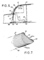
- Figures 5 to 7 show embodiments mainly intended for use with a fan unit mounted in the boot and for fitting to existing vehicles.
- the duct 50 is formed from a channel section 51 of a flexible plastics material having flanges 52 running longitudinally and including an adhesive coated foam plastic strip 53 by which the channel edges may be secured to the roof 54 of a vehicle.
- the channel 51 may have vents 55 formed therein for intake of air, or alternatively additional sections may be provided which couple two channels together, these sections 56 having suitable apertures 57 which may be of variable dimension and adjustable. Sections 56 may be dimensioned to overlap the ducting or to fit inside same with appropriate seals being provided.
- the front end of the ducting can be closed by means of a cap (not shown). Other sections can be provided to enable angular joints to be made between sections of ducting.
- connection to the fan unit may be made by means of the coupling passing through to the vehicle boot, as shown in Figure 6 wherein the channel 51 connects via a coupling 58 with a flexible hose 59 connected with a pipe flange 60 passing through the rear parcel shelf 61, and connected by a further hose 62 with an impeller fan unit 63. Exhaust air may be discharged at 69 into the boot, or conveyed via a further pipe (not shown) externally of the vehicle.
- a manifold provides for both sides of the vehicle to be served by a single fan unit 63.
- Figure 7 shows a further section of ducting 51 and in this arrangement a D-shape section is provided with a base 64 thereof having longitudinally extending corrugations or convolutions 64a, so that it may be readily flexed to fit the curvature of a vehicle roof and secured by adhesive strips or pads 65.
- the outer profile 66 of the ducting may be convoluted radially at 66a to allow flexing in a longitudinal direction.
- various vents and connecting pieces can be provided as in Figures 5 and 6, with suitable sealant or foam plastics being used between the joints.
- the arrangement thus enables a number of basic units to be selectively assembled and fitted to a vehicle according to requirements, by selecting appropriate lengths of ducting and connectors to join same through various angles.
- the extracted air can be filtered and recirculated if required and where heat conservation is important.
- the air may be conditioned in a separate or integral unit and returned to the vehicle.
- the fan unit can be mounted on the rear parcel shelf 61, or within the ducting, by means of a suitable enclosure to form an arrangement similar to that of Figure 4.
Landscapes
- Physics & Mathematics (AREA)
- Thermal Sciences (AREA)
- Engineering & Computer Science (AREA)
- Mechanical Engineering (AREA)
- Air-Conditioning For Vehicles (AREA)
- Motor Or Generator Cooling System (AREA)
- Devices For Conveying Motion By Means Of Endless Flexible Members (AREA)
- Characterised By The Charging Evacuation (AREA)
- Lubrication Details And Ventilation Of Internal Combustion Engines (AREA)
- Body Structure For Vehicles (AREA)
- Ventilation (AREA)
Claims (7)
Priority Applications (1)
| Application Number | Priority Date | Filing Date | Title |
|---|---|---|---|
| AT82902358T ATE25219T1 (de) | 1982-07-23 | 1982-07-23 | Be- und entlueftungssystem fuer motorfahrzeuge. |
Applications Claiming Priority (1)
| Application Number | Priority Date | Filing Date | Title |
|---|---|---|---|
| PCT/GB1982/000226 WO1984000520A1 (fr) | 1982-07-23 | 1982-07-23 | Systeme de ventilation et d'extraction d'air pour vehicules a moteur |
Publications (2)
| Publication Number | Publication Date |
|---|---|
| EP0122255A1 EP0122255A1 (fr) | 1984-10-24 |
| EP0122255B1 true EP0122255B1 (fr) | 1987-01-28 |
Family
ID=10527467
Family Applications (1)
| Application Number | Title | Priority Date | Filing Date |
|---|---|---|---|
| EP82902358A Expired EP0122255B1 (fr) | 1982-07-23 | 1982-07-23 | Systeme de ventilation et d'extraction d'air pour vehicules a moteur |
Country Status (7)
| Country | Link |
|---|---|
| EP (1) | EP0122255B1 (fr) |
| AT (1) | ATE25219T1 (fr) |
| AU (1) | AU561170B2 (fr) |
| BR (1) | BR8208107A (fr) |
| DE (2) | DE8290001U1 (fr) |
| NO (1) | NO157007C (fr) |
| WO (1) | WO1984000520A1 (fr) |
Cited By (1)
| Publication number | Priority date | Publication date | Assignee | Title |
|---|---|---|---|---|
| US10532631B2 (en) | 2017-03-29 | 2020-01-14 | Ford Global Technologies, Llc | Acoustic air duct and air extraction system including a plurality of channels having an expansion chamber |
Families Citing this family (13)
| Publication number | Priority date | Publication date | Assignee | Title |
|---|---|---|---|---|
| DE3734271A1 (de) * | 1987-10-09 | 1989-04-27 | Santec Gmbh | Transportfahrzeug fuer den transport von kontaminiertem erdreich |
| DE3744500A1 (de) * | 1987-12-30 | 1989-07-13 | Klaus Hennig | Belueftungsvorrichtung fuer kfz-innenraeume mit luftzufuehrung von oben = beluvo |
| DE3807417A1 (de) * | 1988-03-07 | 1989-09-28 | Bayerische Motoren Werke Ag | Kraftfahrzeugkarosserie mit seitlichen schwellern |
| DE4103035A1 (de) * | 1991-02-01 | 1992-08-13 | Bayerische Motoren Werke Ag | Belueftungsanordnung fuer einen fahrzeug-innenraum |
| FR2672849B1 (fr) * | 1991-02-14 | 1994-12-09 | Renault | Procede et dispositif de chauffage de ventilation et de climatisation localise d'un habitacle de vehicule automobile. |
| DE4202256C2 (de) * | 1992-01-28 | 1994-11-03 | Beneform Gmbh | Luftkanalanordnung für die Lüftung oder Klimatisierung eines Fahrzeuginnenraumes sowie Verfahren zur Herstellung einer Luftkanalanordnung |
| ES2149660B1 (es) * | 1997-07-24 | 2001-05-01 | Clavero Jose Enrique Montero | Sistema de aspiracion de humos y malos olores en el interior de vehiculos. |
| CN1430558A (zh) * | 2000-03-31 | 2003-07-16 | 山代常一朗 | 汽车室内换气装置 |
| DE102004005481A1 (de) * | 2004-02-04 | 2005-08-25 | Adam Opel Ag | Lüftungssystem |
| DE102005031875B4 (de) * | 2005-07-07 | 2013-05-29 | Webasto Ag | Dachmodul mit Belüftungskanal |
| JP6696815B2 (ja) * | 2016-03-31 | 2020-05-20 | 株式会社Subaru | 車両用空調装置 |
| DE102020002485A1 (de) * | 2019-12-20 | 2021-06-24 | Gentherm Gmbh | Belüftungseinrichtung für eine Fahrzeugkabine |
| DE102022001245A1 (de) | 2022-04-12 | 2022-06-02 | Mercedes-Benz Group AG | Belüftungseinrichtung für ein Fahrzeug |
Family Cites Families (15)
| Publication number | Priority date | Publication date | Assignee | Title |
|---|---|---|---|---|
| GB516448A (en) * | 1937-06-25 | 1940-01-02 | John William Rooney | An improved ventilator or air extractor |
| GB563254A (en) * | 1943-02-06 | 1944-08-04 | Albert Price | Improvements in ventilation of vehicles |
| DE963038C (de) * | 1951-03-01 | 1957-05-02 | Jan Oosterloo | Zugfreie Lueftung fuer geschlossene Fahrzeuge, insbesondere Personenkraftwagen |
| US2853932A (en) * | 1953-06-22 | 1958-09-30 | Frank B Freydl | Ventilating attachment for vehicles |
| FR1183336A (fr) * | 1957-09-25 | 1959-07-06 | Anciens Etablissements Panhard | Dispositif de dégivrage de toutes les surfaces vitrées de véhicules |
| GB839306A (en) * | 1957-10-12 | 1960-06-29 | Daimler Benz Ag | Improvements relating to ventilating means in motor vehicles |
| US3835606A (en) * | 1972-05-22 | 1974-09-17 | M Liberman | Combination ceiling tile and air duct structure |
| DE2247454A1 (de) * | 1972-09-27 | 1974-04-18 | Leonard Diepenbrock | Heiz- oder kuehlluefter |
| DE2704523C2 (de) * | 1977-02-03 | 1986-05-07 | Karl Kässbohrer Fahrzeugwerke GmbH, 7900 Ulm | Omnibus mit einem Luftkanal im Dachbereich |
| DE2803624A1 (de) * | 1978-01-27 | 1979-08-02 | Franz Amschler | Auto-innenrauch-abzug |
| DE2847224A1 (de) * | 1978-10-30 | 1980-05-14 | Lothar Naporra | Bauelement fuer luftfuehrungskanaele |
| US4245924A (en) * | 1978-12-07 | 1981-01-20 | Hancor, Inc. | Arch conduit |
| EP0027276A3 (fr) * | 1979-10-13 | 1981-05-06 | Bern Lüchtrath | Tronçon de conduit transportable |
| FR2468076B1 (fr) * | 1979-10-18 | 1987-05-22 | Air Ind | Gaine de diffusion d'air de ventilation |
| GB2091413B (en) * | 1981-01-19 | 1984-09-26 | Raccah Guy Bernard | Air ventilation and extraction system for motor vehicles |
-
1982
- 1982-07-23 EP EP82902358A patent/EP0122255B1/fr not_active Expired
- 1982-07-23 BR BR8208107A patent/BR8208107A/pt not_active IP Right Cessation
- 1982-07-23 DE DE19828290001U patent/DE8290001U1/de not_active Expired
- 1982-07-23 AT AT82902358T patent/ATE25219T1/de not_active IP Right Cessation
- 1982-07-23 WO PCT/GB1982/000226 patent/WO1984000520A1/fr not_active Ceased
- 1982-07-23 AU AU87649/82A patent/AU561170B2/en not_active Ceased
- 1982-07-23 DE DE8282902358T patent/DE3275283D1/de not_active Expired
-
1984
- 1984-03-08 NO NO84840895A patent/NO157007C/no unknown
Cited By (1)
| Publication number | Priority date | Publication date | Assignee | Title |
|---|---|---|---|---|
| US10532631B2 (en) | 2017-03-29 | 2020-01-14 | Ford Global Technologies, Llc | Acoustic air duct and air extraction system including a plurality of channels having an expansion chamber |
Also Published As
| Publication number | Publication date |
|---|---|
| NO157007B (no) | 1987-09-28 |
| BR8208107A (pt) | 1984-11-27 |
| WO1984000520A1 (fr) | 1984-02-16 |
| ATE25219T1 (de) | 1987-02-15 |
| DE3275283D1 (en) | 1987-03-05 |
| AU8764982A (en) | 1984-02-23 |
| NO157007C (no) | 1988-01-06 |
| EP0122255A1 (fr) | 1984-10-24 |
| NO840895L (no) | 1984-03-08 |
| AU561170B2 (en) | 1987-04-30 |
| DE8290001U1 (de) | 1985-03-28 |
Similar Documents
| Publication | Publication Date | Title |
|---|---|---|
| EP0122255B1 (fr) | Systeme de ventilation et d'extraction d'air pour vehicules a moteur | |
| US6161609A (en) | Flow control apparatus | |
| JPH03235741A (ja) | 自動車の側部窓での曇りおよび氷の形成を阻止する装置 | |
| EP0900718A3 (fr) | Toit de cabine pour moissoneuse-batteuse | |
| GB2124751A (en) | Air extraction system for motor vehicles | |
| US3289564A (en) | Air-conditioning devices for automobile vehicles | |
| US5632673A (en) | Ventilation system for lightweight automobile | |
| US3516707A (en) | Motor vehicle body | |
| CA1281753C (fr) | Renfort transversal pour automobile | |
| US3202076A (en) | Means for extracting air from the body of a vehicle | |
| GB2091413A (en) | Air ventation and extraction system for motor vehicles | |
| CN2276427Y (zh) | 客车通风系统的改良结构 | |
| JPH0645294B2 (ja) | 自動車用空気調和装置 | |
| HU213283B (en) | Top channel arrangement for vehicless with a big space | |
| JPH0224704Y2 (fr) | ||
| JPS5931444Y2 (ja) | バス等車輛のフレッシュエア−導入装置 | |
| KR200248239Y1 (ko) | 자동차의 환기장치 | |
| JPS6345969Y2 (fr) | ||
| JPS6144506Y2 (fr) | ||
| SU1276253A3 (ru) | Воздушна винтил ционна и выт жна система дл автомобил | |
| RU2025404C1 (ru) | Вентиляционная система салона транспортного средства | |
| JPS60182214U (ja) | 自動車の空調装置 | |
| JPS6020529Y2 (ja) | 車両用遮熱構造 | |
| JPS59501306A (ja) | 自動車用換気・排気装置 | |
| RU98102585A (ru) | Способ вентиляции и отопления салона кузова автомобиля и устройство для его осуществления |
Legal Events
| Date | Code | Title | Description |
|---|---|---|---|
| PUAI | Public reference made under article 153(3) epc to a published international application that has entered the european phase |
Free format text: ORIGINAL CODE: 0009012 |
|
| AK | Designated contracting states |
Kind code of ref document: A1 Designated state(s): AT BE CH DE FR GB LI LU NL SE |
|
| 17P | Request for examination filed |
Effective date: 19840815 |
|
| RBV | Designated contracting states (corrected) |
Designated state(s): AT BE CH DE FR LI LU NL SE |
|
| GRAA | (expected) grant |
Free format text: ORIGINAL CODE: 0009210 |
|
| AK | Designated contracting states |
Kind code of ref document: B1 Designated state(s): AT BE CH DE FR LI LU NL SE |
|
| REF | Corresponds to: |
Ref document number: 25219 Country of ref document: AT Date of ref document: 19870215 Kind code of ref document: T |
|
| ET | Fr: translation filed | ||
| REF | Corresponds to: |
Ref document number: 3275283 Country of ref document: DE Date of ref document: 19870305 |
|
| PG25 | Lapsed in a contracting state [announced via postgrant information from national office to epo] |
Ref country code: LU Free format text: LAPSE BECAUSE OF NON-PAYMENT OF DUE FEES Effective date: 19870731 |
|
| PLBE | No opposition filed within time limit |
Free format text: ORIGINAL CODE: 0009261 |
|
| STAA | Information on the status of an ep patent application or granted ep patent |
Free format text: STATUS: NO OPPOSITION FILED WITHIN TIME LIMIT |
|
| 26N | No opposition filed | ||
| PGFP | Annual fee paid to national office [announced via postgrant information from national office to epo] |
Ref country code: LU Payment date: 19900621 Year of fee payment: 9 |
|
| PGFP | Annual fee paid to national office [announced via postgrant information from national office to epo] |
Ref country code: FR Payment date: 19900628 Year of fee payment: 9 Ref country code: BE Payment date: 19900628 Year of fee payment: 9 Ref country code: AT Payment date: 19900628 Year of fee payment: 9 |
|
| PGFP | Annual fee paid to national office [announced via postgrant information from national office to epo] |
Ref country code: DE Payment date: 19900629 Year of fee payment: 9 |
|
| PGFP | Annual fee paid to national office [announced via postgrant information from national office to epo] |
Ref country code: SE Payment date: 19900730 Year of fee payment: 9 |
|
| PGFP | Annual fee paid to national office [announced via postgrant information from national office to epo] |
Ref country code: NL Payment date: 19900731 Year of fee payment: 9 |
|
| PGFP | Annual fee paid to national office [announced via postgrant information from national office to epo] |
Ref country code: CH Payment date: 19900928 Year of fee payment: 9 |
|
| PG25 | Lapsed in a contracting state [announced via postgrant information from national office to epo] |
Ref country code: AT Effective date: 19910723 |
|
| PG25 | Lapsed in a contracting state [announced via postgrant information from national office to epo] |
Ref country code: SE Effective date: 19910724 |
|
| PG25 | Lapsed in a contracting state [announced via postgrant information from national office to epo] |
Ref country code: LI Effective date: 19910731 Ref country code: CH Effective date: 19910731 Ref country code: BE Effective date: 19910731 |
|
| BERE | Be: lapsed |
Owner name: RACCAH GUY BERNARD Effective date: 19910731 |
|
| PG25 | Lapsed in a contracting state [announced via postgrant information from national office to epo] |
Ref country code: NL Effective date: 19920201 |
|
| NLV4 | Nl: lapsed or anulled due to non-payment of the annual fee | ||
| PG25 | Lapsed in a contracting state [announced via postgrant information from national office to epo] |
Ref country code: FR Effective date: 19920331 |
|
| REG | Reference to a national code |
Ref country code: CH Ref legal event code: PL |
|
| PG25 | Lapsed in a contracting state [announced via postgrant information from national office to epo] |
Ref country code: DE Effective date: 19920401 |
|
| REG | Reference to a national code |
Ref country code: FR Ref legal event code: ST |
|
| EUG | Se: european patent has lapsed |
Ref document number: 82902358.9 Effective date: 19920210 |