EP0123573B1 - Verfahren zum adaptiven Kodieren und Dekodieren eines Fernsehbildes und Vorrichtung zur Durchführung dieses Verfahrens - Google Patents
Verfahren zum adaptiven Kodieren und Dekodieren eines Fernsehbildes und Vorrichtung zur Durchführung dieses Verfahrens Download PDFInfo
- Publication number
- EP0123573B1 EP0123573B1 EP84400500A EP84400500A EP0123573B1 EP 0123573 B1 EP0123573 B1 EP 0123573B1 EP 84400500 A EP84400500 A EP 84400500A EP 84400500 A EP84400500 A EP 84400500A EP 0123573 B1 EP0123573 B1 EP 0123573B1
- Authority
- EP
- European Patent Office
- Prior art keywords
- point
- points
- blocks
- value
- coded
- Prior art date
- Legal status (The legal status is an assumption and is not a legal conclusion. Google has not performed a legal analysis and makes no representation as to the accuracy of the status listed.)
- Expired
Links
Images


Classifications
-
- H—ELECTRICITY
- H04—ELECTRIC COMMUNICATION TECHNIQUE
- H04N—PICTORIAL COMMUNICATION, e.g. TELEVISION
- H04N19/00—Methods or arrangements for coding, decoding, compressing or decompressing digital video signals
- H04N19/50—Methods or arrangements for coding, decoding, compressing or decompressing digital video signals using predictive coding
- H04N19/593—Methods or arrangements for coding, decoding, compressing or decompressing digital video signals using predictive coding involving spatial prediction techniques
Definitions
- the invention relates to a coding and decoding method making it possible to reduce the quantity of information of a television picture, to facilitate its transmission or its storage.
- This method allows in particular the coding and decoding of a single image such as that analyzed by certain cameras on board in air reconnaissance planes, a scanning being carried out on the one hand by the movement of the plane, and on the other hand by a linear optical sensor analyzing a single line, this sensor can consist of several charge transfer bars (CCD) placed end to end.
- CCD charge transfer bars
- This method provides a decoded image with defects visible to the eye, since the latter has a sensitivity to coding errors which is not a direct function of the variance of the luminance values in each block.
- the eye is very sensitive to coding errors relating to isolated points where there is a strong luminance gradient.
- the object of the invention is a method providing a decoded image having a better quality, for the eye, since it consists in selecting a quantization scale by taking into account all the points with a strong gradient, even those which are isolated.
- Another advantage of the method according to the invention is that it codes with a smaller amount of information the blocks where there are only points with a low luminance gradient, since it consists in not coding some of these points , their value being restored by an interpolation.
- Another object of the invention is a coding device and a decoding device for the implementation of this method.
- Each point of the image to be coded is represented by the numerical value of its luminance.
- the method according to the invention is an adaptive method because the coding of the luminance value of a point is carried out differently as a function of the gradient of the luminance of the image at this point. If the point considered is located on a contour of an object, the luminance value of this point is significantly different from that of at least one of its neighbors. On the other hand, if the point considered is located in an approximately uniform region of the image, the luminance value at this point is little different from the luminance values of all the immediately neighboring points.
- the information needed to represent these two types of areas is not only different in quantity but also in nature.
- An approximately uniform area contains less information than an area where contours are located, and on the other hand this information corresponds to variations in the luminance value which are smaller.
- the coding and decoding method according to the invention is adaptive to treat these two cases differently. Redoing the choice of a type of coding for each point would complicate coding and decoding and would greatly increase the quantity of coded information since it should contain information indicating the nature of the coding used for each point; this is why the coding method according to the invention retains the same type of coding for a whole block of points. From the start, all the blocks are the same length. Coding by variable length blocks would indeed require a significant amount of information to code the length of each block.
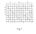
- the method according to the invention consists in grouping the points of the image by blocks of Np consecutive points on the same line, Np being a fixed integer, equal to 4 for example. It then consists in distinguishing two types of blocks and in coding them respectively according to two different types of coding.
- the second type of blocks consists of blocks, called blocks with a low luminance gradient, containing no point with a high luminance gradient.
- the high gradient blocks correspond to the contours of the objects represented by the image, while the low gradient blocks correspond to areas where the luminance is constant or varies slightly.
- Each point of a block with a strong gradient is coded by a differential coding consisting in calculating the difference between the value of its luminance and a value obtained by coding then decoding the value of the luminance of the immediately preceding point, then by quantifying this difference according to a first non-linear quantification scale.
- This differential coding is carried out using as a reference value, not the exact value of the luminance of the immediately preceding point, but using its coded-decoded value, because for the subsequent decoding the reference value used will not be the exact value of the luminance of the previous point, but its decoded value, therefore slightly erroneous.
- the use of an identical reference value for coding and then for decoding avoids introducing an additional error.
- the first non-linear quantization scale is such that the quantization errors are lower for the high values than for the low values of the difference in luminance, because in the blocks with strong gradient the differences in luminance from one point to another are important in general. Thus the quantification errors are minimized statistically.
- the points of the blocks with low luminance gradient are not all coded because the variations in luminance are small, or even zero, inside each block.
- At least one of the points of each block is coded by differential coding, and the other points are not coded at all, but their luminance value can be reconstituted by an interpolation.
- the first and the third point of each block are coded by a differential coding consisting in calculating the difference between the luminance value of the point considered and a value obtained and then coding by decoding the luminance value of a point, called a reference point, chosen from the points having been coded previously, then by quantifying the value of this difference according to a second non-linear quantization scale.
- the first point of each low gradient block is differentially coded with the fourth point of the immediately preceding block as its reference point, regardless of the type of this block, and the third point of each low gradient block is coded with for the second point reference point of this same block.
- the second non-linear quantization scale is such that the quantization error is smaller for the low values than for the large values of the difference in luminance.
- the differences in luminance are generally small, the errors due to the quantization are therefore minimized statistically.
- the second and fourth points of each block with a low gradient are not coded, this therefore results in a significant reduction in the amount of information.
- the luminance values of the points of the blocks with high gradient are coded by binary words of three bits while the luminance values in the blocks with low gradient are coded by binary words of two bits.
- the high gradient blocks represent approximately 15% of the set of four point blocks constituting an image. This percentage is directly linked to the number of points Np contained in each block. If Np is chosen larger than qutre the percentage of blocks with strong gradient is more important and consequently the quantity of information to be transmitted is more important.
- the type of each block must be distinguished by a logical indicator in order to be able to decode the two types of blocks differently. This logical indicator consists of one bit per block, so it increases the amount of information, all the more the number of points per block is lower. The choice of the number Np of points per block is therefore a compromise between these two constraints.
- each block contains a constant number of points and it suffices to carry out a counting to determine, both during coding and during decoding, where begins and where each block ends.
- Decoding first consists in identifying the type of each block according to the value of the logic indicator. Each point of a block with a strong gradient is decoded by quantizing an encoded value according to a scale opposite to the first quantization scale used for coding in order to obtain a luminance difference value which can range from 0 to 255, then adding this difference in luminance value to the luminance value decoded from the previous point.
- each point which has been coded is decoded by quantifying the coded value according to a quantization scale opposite to the second quantization scale used for coding and then adding the value obtained to the value of the decoded luminance of the reference point, which here is the previous point.
- the points which are decoded in this way are the first and the third point of each block with a low gradient.
- the first point has for reference point the last point of the preceding block and the third point has for reference point the second point of the same block, as for coding.
- the luminance values of the second and fourth point of each block with a low gradient, which have not been coded, are reconstructed by an interpolation as a function of the decoded luminance values of the neighboring points on the same line and on the previous line.
- the decoded luminance value for the second point is equal to half the sum of the decoded luminance value of the first point of the same block and the decoded luminance value of the point following the homologous point on the previous line.
- the decoded luminance value of the fourth point of a block with a low gradient is equal to half a sum of the decoded value of the luminance of the third point of the same block and the decoded luminance value of the point following the point counterpart on the previous line.
- the interpolation method can include many variants, in particular as regards the weighting coefficients used.
- the choice of points to be coded and points not to be coded in blocks with a low luminance gradient may be different from that described above, the scope of the invention is not limited to this example.
- the luminance values are little different from those of the homologous points on the previous line, because if it were otherwise for at least one of its points the block would be considered a high gradient block. Consequently, the interpolation errors are small.
- a variant of the method according to the invention in order to obtain a better reproduction of the areas with a low gradient in an image, consists in coding the points with high gradient and the points with low gradient of the blocks with high gradient differently, using a quantification scale. nonlinear different for these two types of points.
- the quantization scale used for the points with low gradient of the blocks with high gradient can be the same as that used to code the points for the blocks with low gradient.
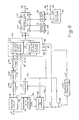
- FIG. 2 represents the block diagram of an exemplary embodiment of a coding device according to the invention, for the implementation of the method described above.
- This device comprises a device 13 for detecting points with a strong gradient, a device 19 for detecting blocks with a strong gradient, control means 22, coding means 25, decoding means 26, and a device 16 for setting forms coded information.
- the decoding device according to the invention receives on an input terminal 11 the series of digital values of the luminance of the points of an image, and on an input terminal 12 a positive digital value. AT. The sequence of luminance values is applied to an input of the device 13, then the latter restores it with a certain delay, to an input terminal 14 of the coding means 25.
- the decoding means 26 determine have a decoded value of the luminance of the current point as soon as its coded value has been determined, they consist of a device 23 for decoding the points of the blocks with a strong gradient and a device 24 for decoding the points of the blocks low gradient, having inputs respectively connected to the outputs of the coding device 15 and of the coding device 20, and having outputs respectively connected to an input of the coding device 15 and to an input of the coding device 20, and providing the decoded value of the luminance of the point preceding the current point.
- the output terminal 27 is connected to an input of the device 16 for shaping the information, and an output thereof constitutes an output terminal 17 of the coding device according to the invention.
- the calculating device 36 has two inputs receiving the values X j n + 3 and X respectively. j n + 2 , and determines
- the calculation device 37 has two inputs receiving respectively the values X j n + 3 and X j ⁇ 1 n + 3 , and determines 1.
- the calculation devices 36 and 37 thus determine the absolute value of the difference in luminance of the point of rank n + 3 on the line of rank j with respect to the immediately preceding point on the same line and with respect to the homologous point on the line former.
- the two values which they supply are applied respectively to a first input of a comparator 38 and to a first input of a comparator 39.
- the device 19 provides on its output terminal 21 a logic signal TB indicating the type of block to which the point belongs, of tang n on the line of rank j,. Which is being coded.
- the output of the OR gate 40 of the device 13 provides a logic signal with a value G j n + 3 indicating whether the point of rank n + 3 on the line of rank j is a point with a strong gradient or a weak gradient, and this value is supplied to an input of the register 41 and to a first input of the OR gate 44.
- the outputs of the registers 41, 42 and 43 respectively supply values G j n + 2 G j n + 1 and G j n indicating whether the points of rank n + 2, n + 1, and n, on the same line are with a strong gradient. These values are applied respectively to a second, a third, and a fourth input of the OR gate 44.
- the output of the OR gate 44 is connected to the input of the register 45, and the output of the latter is connected to the output terminal 21 of the device 19.
- a logic level j is applied to one of the OR gate 44 inputs and the output thereof provides a logic level 1 at the input of register 45.
- the logic level present at the output of gate 44 is memorized under the action of the clock signal HB.
- the logic signal of value TB supplied by the output of register 45 then remains constant during the coding of four points, and it designates the type of the block constituted by these four points.
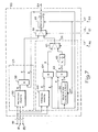
- FIG. 5 represents a more detailed block diagram of the coding means 25, of the decoding means 26, and of the device 16 for shaping the coded information.
- the means 25 mainly comprising a device 15 for coding the points of the blocks with a high gradient and a device 20 for coding the points of the blocks with a low gradient.
- the device 15 consists of a subtractor 50 and a read only memory 51
- the device 20 consists of a subtractor 52 and a read only memory 53.
- the means 25 also comprise a multiplexer 54 with two inputs and a exit. This output is connected to the output terminal 27 of the means 25.
- the output terminal 14 of the device 13 for detecting points with a strong gradient provides, at an instant considered, a luminance value X ;, at a first input of the subtractor 50 and at a first input of the subtractor 52.
- An output of the decoding means 26 provides a value X ' j n-1 , decoded value of the luminance of the point of rank n-1 on the row of rank j, which is the point preceding the point which is being coded at the instant considered. This value is applied to a second input of the subtractor 50 and to a second input of the subtractor 52.
- the subtractors 50 and 52 have two outputs connected respectively to an address input of the read only memory 51 and to an address input of the read only memory 53.
- Subtractors 50 and 52 could be combined into a single subtractor.
- Read only memories 51 and 53 carry out a non-linear quantization which is different for the coding of the points of the blocks with high gradient and for the coding of the points of the blocks with low gradient.
- the ROM 51 performs quantization on a non-linear scale comprising eight levels such that the quantization error on the highest values is small.
- the memory 53 performs quantization on a non-linear scale comprising four levels such that the quantization error on the lowest values is small.
- the multiplexer 54 is controlled by the logic signal TB so as to select the value supplied by the output of the memory 51 or the value supplied by the output of the memory 53 according to the type of block, then this value is supplied to the terminal outlet 27.
- the decoding means 26 mainly comprise a device 23 for decoding the points of the blocks with a high gradient and a device 24 for decoding the points of the blocks with a low gradient, having two inputs connected respectively to the output of the device 15 and to the output of the device 20.
- the means 26 furthermore comprise a multiplexer 56 with two inputs and an output, and a register 55 with one stage and the output of which constitutes the output of the means 26 and provides at the instant considered the decoded luminance value X ′ j n-1 .
- the device 23 for decoding the points of the blocks with a high gradient comprises a read-only memory 59, and an adder 58.
- the address input of the read-only memory 59 constitutes the input of the device 23, and receives a value coded on three bits provided by the read-only memory 51.
- the memory 59 performs a quantization on a scale opposite to that of the quantization carried out by the memory 51 and provides a nine-bit coded value which is the luminance difference value. This difference in luminance can only take eight values, which are distributed from -255 to +255, and which are equal to the values of the thresholds of the quantization carried out for coding.
- This value is applied to a first input of the adder 58 which receives on a second input the decoded luminance value X ' j n-1 of the previously coded point, supplied by the output of the register 55.
- the output of the adder 58 constitutes the output of the device 23 and is connected to a first input of the multiplexer 56.
- a second input of the multiplexer 56 is connected to an output of the device 24, and the output of the multiplexer 56 is connected to the input of the register 55.
- the multiplexer 56 is controlled by the signal TB in order to select either the value supplied by the device 23 or the value supplied by the device 24 according to the type of block to which the point which is being coded in the means 25 belongs, since its decoding has takes place simultaneously in the means 26.
- the decoded value transmitted by the multiplexer 56 is stored by the register 55 under the action of the clock signal HP in order to be available for coding and decoding the luminance value of the p next point that will be treated.
- the device 24 for decoding the points of the blocks with a low gradient comprises a read only memory 65, two adders 63 and 64, a shift register 66, a divider by two 62, and a multiplexer 61 with two inputs and one output.
- a first input of the device 24 is constituted by an address input of the read-only memory 65 and is connected to the output of the device 20 for coding the points of the blocks with low gradient, they therefore receive values coded on two bits.
- a data output of the read-only memory 65 provides an eight-bit binary word to a first input of the adder 64.
- a second input of the adder 64 receives the decoded value X'1.-1 supplied by the output of the register 55.
- the read-only memory 65 performs an inverse quantization of the non-linear quantization performed by the memory 53 for coding, that is to say provides a value between -255 and +255, and equal to one of the values coding quantification thresholds.
- the adder 64 adds the luminance difference value supplied by the memory 65 to the decoded luminance value of the point previously treated.
- the register 66, the adder 63, and the divider 62 make it possible to reconstruct a luminance value by interpolation.
- the register 66 has a serial input connected to the output of the register 55, and a serial output connected to a first input of the adder 63.
- a second input of the adder 63 is connected to the output of the register 55, and an output is connected to the input of the divider 62.
- the register 66 has a number of stages corresponding to a line plus a point and is controlled by the point clock signal HP. At the instant considered the serial input of the register 66 receives the decoded value X'11 of the luminance of the point preceding the point which is being coded by the means 25 and which is being decoded by the means 26, and the serial output of register 66 provides a decoded value X'j-l of the point of rank n on the line of rank j-1.
- the adder 63 and the divider 62 determine the half-sum of the values X'jn-1 and X ' j n-1 .
- the output of the adder 64 supplies a decoded luminance value corresponding to the point of rank n on the row of row j at a first input of the multiplexer 61.
- the multiplexer 61 receives on a second input the value reconstituted by the interpolation, supplied by the output of the divider 62.
- the multiplexer 61 is controlled by the logic signal TP so as to select one of these values as a function of the type of the point which is being coded and decoded. If this point is effectively coded, the multiplexer 61 transmits the decoded value supplied by the adder 64, and if this point has not been coded, the multiplexer 61 transmits the reconstituted luminance value supplied by the output of the divider 62.
- the output of the multiplexer 61 constitutes the output of device 24 and is connected to a second input of multiplexer 56.
- the address inputs of the read only memories 59 and 65 can be connected respectively to the output of the subtractor 50 and to the output of the subtractor 52, they then receive binary words of eight bits and provide eight-bit binary words directly giving the values resulting from the succession of coding quantization and decoding quantization.
- the device 16 for formatting coded information comprises a control device 70, a multiplexer 71 with four inputs and one output, and a device 72 for formatting in HDLC format.
- the multiplexer 71 has four inputs respectively receiving the three bits supplied by the output terminal 27 of the coding means 25 and the bit of the signal TB.
- the multiplexer 71 has an output providing a bit to an input of the device 72, and a control input receiving a binary word supplied by the control device 70 as a function of the logic signals TB and TP, and the clock signals HB and HP .
- the device 72 also has a validation input (val.) And a synchronization input (syn.) Receiving respectively a signal supplied by the control device 70 and the line synchronization signal HL.
- the output of the device 72 is connected to the output terminal 17 of the coding device according to the invention.
- the control device 70 receives the block clock signal HB it controls the multiplexer 71 to transmit the value of the signal TB indicating the type of the block. Then, at each pulse from the point clock HP, the multiplexer 71 transmits the value of one of the bits supplied by the output terminal 27 of the coding device 25. For each bit transmitted by the multiplexer 71 the control device 70 provides a validation pulse at the validation input of the device 72. These pulses are generated at a frequency four times higher than that of the point clock HP, and their number is a function of the value of the signals TP and TB.
- a second input of the AND gate 99 is connected to the output of the register 97, the latter being connected on the other hand to an input terminal 87 of the means 83.
- the frequency divider by two 100 has an input connected to the output of the AND gate 99 and an output connected to an input terminal 86 of the means 83.
- This clock signal is applied to the counting device 98 to trigger a counter there in order to divide the frequency of the clock signal SBI in the report 13 or in the report 5 according to whether the coded data during reception corresponding to the points of a block with strong gradient or to the points of a low gradient block respectively.
- the counting ratio is selected according to the value of a logic signal TBL indicating the type of block and which is supplied by the output of register 97.
- the clock signal thus obtained is called point synchronization signal, SP, and is provided on the second output of the counting device 98.
- the write address pointer 91 receives the synchronization signals SL and SP which are determined from the coded information received, while the read address pointer 92 is incremented by the synchronization signals SL 'and SP' generated by the control means 95 and which synchronize the reading of the memory 89 with the display.
- the adder 63 has a first input receiving eight bits supplied by the output of register 55, a second input receiving eight bits supplied by the output of register 66, and an output providing eight bits to an input of the divider by two 62.
- An output of the divider 62 is connected to a second input of the multiplexer 61.
- the output of the multiplexer 61 is connected to a second input of the multiplexer 56.
- the output of the multiplexer 56 is connected to an input of the register 55.
- the output of the register 55 is further connected to the output terminal 84 of the decoding means 83.
- the read-only memory 59 re-quantizes according to a non-linear scale inverse to the quantization scale of the memory 51 for coding, then the adder 58 adds the value supplied by the memory 59 to the luminance value decoded immediately previously in order to d '' obtain a decoded luminance value for the current point.
- the read only memory 65 performs a quantization on an inverse scale to that performed by the memory 53 to code the first point and the third point of the blocks with low gradient, then the adder 64 adds the value supplied by the read only memory 65 to the last luminance value which has been decoded.
- the adder 63 and the divider by two 62 reconstitute the luminance value of a second or third point of a low gradient block by adding the decoded luminance value of the point preceding the current point and the decoded luminance value of the point following the homologous point of the current point on the previous line, then dividing by two the sum obtained.
- the multiplexer 61 transmits either the decoded luminance value supplied by the adder 64, or the reconstituted luminance value by interpolation, supplied by the output of the divider 62.
- the invention is not limited to the embodiment described above. It is notably within the reach of those skilled in the art to choose differently: the number of points per block as a function of the nature of the images, the number and the order of the points which are coded in the blocks with a low gradient, the weighting coeffices used for the interpolation of the luminance values reconstituted in the blocks with low gradient. It is also within its reach to produce a coding device and a device for decoding the points of blocks with a strong gradient achieving a coding and decoding with different quantization scales for points with low gradient and for points with high gradient, blocks with high gradient.
- the coding device and the decoding device according to the invention can be used not only for transmission, but also for storage, for example on magnetic tape.
- the rate of output of the data from the coding device may be completely different from the rate of entry of this data into the decoding device using a different recording speed and reading speed.
- Adaptation of the color television coding and decoding devices can be accomplished simply by using three similar devices, one for the luminance signal, and one for each of the color difference signals.
Landscapes
- Engineering & Computer Science (AREA)
- Multimedia (AREA)
- Signal Processing (AREA)
- Compression Or Coding Systems Of Tv Signals (AREA)
Claims (6)
Applications Claiming Priority (2)
| Application Number | Priority Date | Filing Date | Title |
|---|---|---|---|
| FR8304671A FR2543384A1 (fr) | 1983-03-22 | 1983-03-22 | Procede de codage adaptatif, et de decodage, d'une image de television, et dispositifs pour la mise en oeuvre de ce procede |
| FR8304671 | 1983-03-22 |
Publications (2)
| Publication Number | Publication Date |
|---|---|
| EP0123573A1 EP0123573A1 (de) | 1984-10-31 |
| EP0123573B1 true EP0123573B1 (de) | 1988-05-11 |
Family
ID=9287101
Family Applications (1)
| Application Number | Title | Priority Date | Filing Date |
|---|---|---|---|
| EP84400500A Expired EP0123573B1 (de) | 1983-03-22 | 1984-03-13 | Verfahren zum adaptiven Kodieren und Dekodieren eines Fernsehbildes und Vorrichtung zur Durchführung dieses Verfahrens |
Country Status (4)
| Country | Link |
|---|---|
| US (1) | US4567519A (de) |
| EP (1) | EP0123573B1 (de) |
| JP (1) | JPS59178887A (de) |
| FR (1) | FR2543384A1 (de) |
Families Citing this family (8)
| Publication number | Priority date | Publication date | Assignee | Title |
|---|---|---|---|---|
| FR2551290B1 (fr) * | 1983-08-30 | 1985-10-11 | Thomson Csf | Procede et dispositif de detection de points en mouvement dans une image de television pour systemes de television numerique a compression de debit a rafraichissement conditionnel |
| US4780718A (en) * | 1985-06-17 | 1988-10-25 | Hughes Aircraft Company | Sar image encoding for data compression |
| JP2612557B2 (ja) * | 1985-12-18 | 1997-05-21 | ソニー株式会社 | データ伝送受信システム及びデータ復号装置 |
| JPS62193380A (ja) * | 1986-02-19 | 1987-08-25 | Nec Corp | 画像信号符号化復号化方式とその装置 |
| GB2189366B (en) * | 1986-04-17 | 1989-12-28 | British Broadcasting Corp | Method and apparatus for conveying information signals |
| US4947447A (en) * | 1986-04-24 | 1990-08-07 | Hitachi, Ltd. | Method for data coding |
| US4994927A (en) * | 1989-06-19 | 1991-02-19 | Gte Laboratories Inc | Self-adaptive neural net based vector quantizer for image compression |
| FR2869751A1 (fr) * | 2004-04-28 | 2005-11-04 | Thomson Licensing Sa | Appareil et procede de traitement d'images |
Family Cites Families (7)
| Publication number | Priority date | Publication date | Assignee | Title |
|---|---|---|---|---|
| US3071727A (en) * | 1961-05-08 | 1963-01-01 | Bell Telephone Labor Inc | Bandwidth reduction system |
| US3824590A (en) * | 1973-03-26 | 1974-07-16 | Bell Telephone Labor Inc | Adaptive interpolating video encoder |
| DE2559263C3 (de) * | 1975-12-31 | 1980-07-31 | Deutsche Forschungs- Und Versuchsanstalt Fuer Luft- Und Raumfahrt E.V., 5000 Koeln | Ausgleich von Quantisierungsverzerrungen bei Bildcodierung mit Blockquantisierung |
| US4268861A (en) * | 1978-09-18 | 1981-05-19 | Massachusetts Institute Of Technology | Image coding |
| FR2461405A1 (fr) * | 1979-07-09 | 1981-01-30 | Temime Jean Pierre | Systeme de codage et de decodage d'un signal visiophonique numerique |
| JPS56136093A (en) * | 1980-03-26 | 1981-10-23 | Fuji Photo Film Co Ltd | Adaptive quantizer |
| FR2503966B1 (fr) * | 1981-04-14 | 1986-10-10 | Thomson Csf | Procede de transmission d'une image, a debit reduit; systeme de transmission pour la mise en oeuvre de ce procede |
-
1983
- 1983-03-22 FR FR8304671A patent/FR2543384A1/fr not_active Withdrawn
-
1984
- 1984-03-13 EP EP84400500A patent/EP0123573B1/de not_active Expired
- 1984-03-20 US US06/591,479 patent/US4567519A/en not_active Expired - Fee Related
- 1984-03-22 JP JP59053673A patent/JPS59178887A/ja active Pending
Also Published As
| Publication number | Publication date |
|---|---|
| EP0123573A1 (de) | 1984-10-31 |
| JPS59178887A (ja) | 1984-10-11 |
| FR2543384A1 (fr) | 1984-09-28 |
| US4567519A (en) | 1986-01-28 |
Similar Documents
| Publication | Publication Date | Title |
|---|---|---|
| EP0323363B1 (de) | Verfahren zur Synchronisierung für die Übertragung über einen asynchronen Kanal einer Folge von kodierten Bildern, die mittels eines Kodes mit variabler Länge kodiert sind und Einrichtung zur Durchführung dieses Verfahrens | |
| US20070025482A1 (en) | Flexible sampling-rate encoder | |
| FR2596221A1 (fr) | Systeme de filtre median adaptif | |
| FR2467520A1 (fr) | Dispositif d'enregistrement de videodisque et dispositif decodeur de videodisque avec appareil pour la synchronisation du cadrage du mot de donnee enregistre et du tourne-videodisque sur le mot de donnee enregistre | |
| FR2467518A1 (fr) | Dispositif pour reduire des erreurs de parcours de l'aiguille dans le sillon d'un videodisque et dispositif d'affichage de la position du programme | |
| FR2532138A1 (fr) | Procede de compression de debit de donnees successivement transmises entre un emetteur et un recepteur de television et systeme mettant en oeuvre le procede | |
| EP0142439A2 (de) | Verfahren zur Kompression einer Folge digitaler Informationen und Vorrichtung dafür | |
| EP0143010A1 (de) | Verfahren und Vorrichtung zum Ermitteln von sich in einem Fernsehbild bewegenden Punkten für digitale Flussverdichtungs-Fernsehsysteme mit konditioneller Auffrischung | |
| EP0123573B1 (de) | Verfahren zum adaptiven Kodieren und Dekodieren eines Fernsehbildes und Vorrichtung zur Durchführung dieses Verfahrens | |
| EP0135405B1 (de) | Verfahren und Vorrichtung zum Ermitteln von sich in einem Fernsehbild bewegenden Punkten für digitale Flussverdichtungs-Fernsehsysteme mit konditioneller Auffrischung | |
| EP0204635A1 (de) | Verfahren zur Übertragung von digitaler Information in Wörterblöcken | |
| EP0400520B1 (de) | Schaltungsanordnung zur Detektion des Verlustes eines digitalen, empfangenen Signals für digitale Signalempfänger | |
| EP0338899B1 (de) | Verfahren zur Kodierung und Dekodierung von Blockinformationen und Vorrichtung dazu | |
| WO1987003769A1 (fr) | Procede et dispositif de compression par codage conditionnel d'images numeriques sans perte d'informations | |
| EP0053064B1 (de) | Digitales Übertragungssystem mit adaptiver Codierung abgetasteter und orthogonal transformierter, analoger Informationen | |
| EP0063990B1 (de) | Verfahren zur Bildübertragung mit beschränktem Datafluss; Übertragungssystem zur Durchführung dieses Verfahrens | |
| EP0224957B1 (de) | Verfahren und Einrichtung zur Bewegungsabschätzung in einer Bildfolge | |
| EP0286192B1 (de) | Verfahren und Gerät zur Bewegungsabschätzung in einer Bildfolge | |
| EP0294282B1 (de) | Verfahren zur temporalen Interpolation von Bildern und Einrichtung zur Durchführung dieses Verfahrens | |
| EP0241983B1 (de) | Bildverarbeitungsvorrichtung zur Schätzung der Verschiebung in Bildern befindlicher Objekte | |
| FR2460580A1 (fr) | Dispositif pour le suivi et l'estimation recursive de l'etat local des contours d'images et application a la prediction adaptative en codage differentiel de signaux de television | |
| EP0098198A2 (de) | Verfahren und Einrichtung zur Kompression der Datenrate von Daten, welche zwischen mindestens einem Sender und einem Empfänger von Fernsehbildern übertragen werden | |
| EP0690623B1 (de) | Verfahren und Einrichtung zur Einfügung von asynchronen Daten in ein digitales Signal | |
| EP0113269B1 (de) | Verfahren zum Unterscheiden zwischen Geräusch und Bewegung in einer Folge von Videobildern und Bewegungsdetektorvorrichtung zur Durchführung des Verfahrens | |
| EP0127525A1 (de) | Verfahren und Vorrichtung zum Kodieren mit geringen Datenflusskosten für Fernsehsysteme mit konditioneller Auffrischung |
Legal Events
| Date | Code | Title | Description |
|---|---|---|---|
| PUAI | Public reference made under article 153(3) epc to a published international application that has entered the european phase |
Free format text: ORIGINAL CODE: 0009012 |
|
| AK | Designated contracting states |
Designated state(s): DE GB IT NL |
|
| 17P | Request for examination filed |
Effective date: 19850306 |
|
| 17Q | First examination report despatched |
Effective date: 19860822 |
|
| GRAA | (expected) grant |
Free format text: ORIGINAL CODE: 0009210 |
|
| AK | Designated contracting states |
Kind code of ref document: B1 Designated state(s): GB |
|
| GBT | Gb: translation of ep patent filed (gb section 77(6)(a)/1977) | ||
| PGFP | Annual fee paid to national office [announced via postgrant information from national office to epo] |
Ref country code: GB Payment date: 19890228 Year of fee payment: 6 |
|
| PLBE | No opposition filed within time limit |
Free format text: ORIGINAL CODE: 0009261 |
|
| STAA | Information on the status of an ep patent application or granted ep patent |
Free format text: STATUS: NO OPPOSITION FILED WITHIN TIME LIMIT |
|
| 26N | No opposition filed | ||
| PG25 | Lapsed in a contracting state [announced via postgrant information from national office to epo] |
Ref country code: GB Effective date: 19900313 |
|
| GBPC | Gb: european patent ceased through non-payment of renewal fee |