EP0241983B1 - Bildverarbeitungsvorrichtung zur Schätzung der Verschiebung in Bildern befindlicher Objekte - Google Patents
Bildverarbeitungsvorrichtung zur Schätzung der Verschiebung in Bildern befindlicher Objekte Download PDFInfo
- Publication number
- EP0241983B1 EP0241983B1 EP87200635A EP87200635A EP0241983B1 EP 0241983 B1 EP0241983 B1 EP 0241983B1 EP 87200635 A EP87200635 A EP 87200635A EP 87200635 A EP87200635 A EP 87200635A EP 0241983 B1 EP0241983 B1 EP 0241983B1
- Authority
- EP
- European Patent Office
- Prior art keywords
- image
- displacement
- value
- estimation
- vector
- Prior art date
- Legal status (The legal status is an assumption and is not a legal conclusion. Google has not performed a legal analysis and makes no representation as to the accuracy of the status listed.)
- Expired - Lifetime
Links
Images


Classifications
-
- H—ELECTRICITY
- H04—ELECTRIC COMMUNICATION TECHNIQUE
- H04N—PICTORIAL COMMUNICATION, e.g. TELEVISION
- H04N19/00—Methods or arrangements for coding, decoding, compressing or decompressing digital video signals
- H04N19/50—Methods or arrangements for coding, decoding, compressing or decompressing digital video signals using predictive coding
- H04N19/503—Methods or arrangements for coding, decoding, compressing or decompressing digital video signals using predictive coding involving temporal prediction
- H04N19/51—Motion estimation or motion compensation
- H04N19/577—Motion compensation with bidirectional frame interpolation, i.e. using B-pictures
-
- G—PHYSICS
- G06—COMPUTING OR CALCULATING; COUNTING
- G06T—IMAGE DATA PROCESSING OR GENERATION, IN GENERAL
- G06T7/00—Image analysis
- G06T7/20—Analysis of motion
- G06T7/277—Analysis of motion involving stochastic approaches, e.g. using Kalman filters
Definitions
- the present invention relates to an image processing device for estimating D (Z i ) of the displacement of objects located therein, device constituted from an estimation member by Kalman filtering which provides for each point "i" of image coordinates Z i a displacement vector DK (Z i ) from the information contained in two successive images I (Z i , t) and I (Z i , t-TR) separated by TR time.
- I (Z i , t) and I (Z i , t-TR) represent the luminance of the image at point "i", Z i the vertical coordinates Y i and horizontal X i of this point "i".
- the invention can also find applications for the pursuit of targets, cell analysis in biology, etc.
- Document DE-A-3328341 describes a video image coding device comprising two cascaded motion estimation members, each of which provides a vector representative of the displacement of objects contained in the image, for each variable image area .
- the invention provides a device of the type mentioned in the preamble of claim 1 which provides a more reliable estimation of the displacement and virtually eliminates the risks of divergence in the filtering operation.
- a second estimation member is provided to provide for each point "i" of the image a displacement vector DB (Z i ) from the luminance information contained in two images.
- a quality measuring device to assess the vectors DK (Z i ) and DB (Z i ) and to act on a vector selector DK (Z i ) or DB (Z i ) so that the vector D (Z i ) provided by the device, that of the two vectors DB (Z i ) and DK (Z i ) giving the best quality of estimation and in that there is provision for access to the first estimating member, which is preferably a KALMAN filtering member, to receive this selected vector D (Z i ).
- any beginning of divergence of the KALMAN filtering operations is neutralized and the access to receive D (Z i ) makes it possible to reinitialize them on good bases.
- the second estimator by its own qualities can be superior to the KALMAN filtering organ.
- the second organ is of the type described in the article entitled "A Motion-Compensated Interframe Coding Scheme for Television Pictures" written by YUICHI NINOMIYA and YOSHIMICHI OHTSUKA and published in pages 201 to 211 of the journal IEEE TRANSACTIONS ON COMMUNICATIONS, volume COM -30, No. 1, January 1982, experience shows that for 10% of the time, it is the latter body that provides the best estimate while for the rest of the time the Kalman filter body is to as much higher than it was reset by information from the second displacement estimation body.
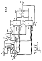
- FIG. 1 schematically shows an image processing device according to the invention.
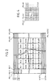
- FIG. 2 shows the organization of an image, in blocks and in image elements.
- FIG. 3 is a time diagram showing the main operating cycles of the device of the invention.
- Figure 4 shows the organization of a block of images.
- FIG. 5 shows a diagram of an embodiment of a second filtering member operating by block correlation.
- FIG. 6 is a time diagram showing the operation of the second filtering member shown in FIG. 5.
- FIG. 7 shows an embodiment diagram of the first KALMAN estimation member combined with the quality measurement member and the vector selector.
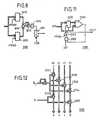
- Figure 8 shows the structure of a motion detector.
- FIG. 9 is a time diagram for the explanation of the operation of the members shown in FIG. 7.
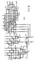
- FIG. 10 is a diagram of a first calculation network forming part of the KALMAN estimation unit of FIG. 7.
- Figure 11 is a diagram of a quality measuring member.
- FIG. 12 is a diagram of a second calculation network forming part of the KALMAN estimation unit of FIG. 7.
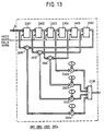
- FIG. 13 shows an embodiment of a digital low-pass filter used in the KALMAN estimation member shown in FIG. 7.
- FIG. 1 there is shown schematically the image processing device for the estimation of the displacement of objects in them.
- This device comprises a first memory 1 for storing all the information relating to an image of a sequence of images and a second memory 2 for storing the following image of the sequence.
- this displacement DK (i) is a vector quantity with two components DK x (i) and DK y (i).
- the component DK x represents the horizontal displacement in the direction of the lines and the component DK y the vertical displacement in the direction perpendicular to these.
- the device shown in FIG. 1 is remarkable in that there is provided a second estimation member 60 for providing for each point "i" a displacement vector DB (i) of components DB x (i), DB y (i), a quality measurement member 70 for assessing DB (i) and DK (i) and to act on a vector selector 80 so that the vector D (i) is that of the two vectors DB (i) and DK (i) giving the best quality of estimation and in what is provided access 90 on the filtering member 50 to receive this vector D (i).
- the second estimator 60 performs a block correlation described in the aforementioned second article, the estimation of the vector DB (i) is performed first during the period of time TB occurring after the period of time TW at the rate of the signals HB supplied by the time base 15.
- This member 60 uses the words contained in the memories 1 and 2; for this it is provided with ADOB and ADNB access to transmit address codes to memories 1 and 2 via switches 81 and 82.
- the data outputs of these memories are set to the state passing by BMN signals and BMO acting for the first via gate 18 and for the second via OR gate 83.
- a signal generated by the time base 15 causes the change of position of the switches 81 and 82, relating the address code entries of the memories 1 and 2 to the ADNK and ADNO accesses provided on the filtering member 50.
- KMN and KMO signals applied to these memories via doors 18 and 83 make the data thereof accessible.
- the estimation of the vectors DK (i) is then carried out by means of the estimation member 50 during the time lapse TK at the rate of signals HK supplied by the time base 15.
- the quality measurement member 70 compares for each point "i" the vectors DK (i) with the vectors DB (i) therefore relating to the same point "i"; the one which gives the best estimate of the displacement is retained by means of the selector 80 to, on the one hand, constitute the vector D (i) of effective displacement and to, on the other hand, to be used by the filtering member of KALMAN 50 for the estimation of the vector DK (i + 1).
- the estimation unit 60 operating on the aforementioned bases is represented in FIG. 5. It firstly consists of two registers 1002 and 1004 intended respectively to store the binary words coming from memories 1 and 2 which are addressed by the address codes transmitted on ADOB and ADNB accesses. BMN and BMO signals developed by means of a clock circuit 1005 from the signal HB are active for reading these memories and they allow the recording in these registers of words read from these memories.
- a calculation unit 1006 performs the correlation calculation for each of the blocks envisaged and the output value is validated by a signal FBL signaling the end of a processing of a block; the result of this calculation unit is applied on the one hand to the input of a register 1008 and on the other hand to an input of a subtraction member 1010 whose other input is connected to the output of register 1008 From the result produced by this organ 1010, we only consider the value of its sign.
- This value authorizes or not the loading of the correlation value in the register 1008, authorizes or not the loading of a value DM (b) coming from a read-only memory 1012 in a register 1014 and finally controls the switching position of a switch 1016.
- the adder 1020 performs the sum of the values available at the output of the switch 1016 and of the register 1022.
- Another adder bearing the reference 1030 performs the sum of the values appearing on the one hand at the output of the accumulator member 1018 or more precisely at the output of register 1022 and on the other hand at the output of read-only memory 1012.
- This adder 1030 provides to another adder 1032 the value to be added to the read address code of memory 2 (ADNB code) to obtain the memory reading code 1 (ADOB code).
- the ADNB code is obtained by an adder 1034 which sums the contents of different counters 1036, 1038 and 1040.
- the counter 1036 is a modulo 8 counter whose content is used to address the 8 image elements (pel) of a block line; the HB count signals are divided by eight at the output of this counter and then increment the content of the modulo counter 8, 1038 to address the 8 lines of a block; the output signals from this counter 1038 are applied to the input of counting signals from a modulo counter 9, referenced by 1042 and the output signals from this counter 1042 to a modulo counter 3, 1044.
- the contents of counter 1040 modulo "5478" incrementing on the output signals from counter 1042 gives the address of the block.
- this counter 1040 is also used to address the memory 1026 via the switch 1027, and thus to store the values DB (i).
- the switch 1027 can connect the addressing input of memory 1026 to the output of a transcoding device 1050 which gives the address of the block for any code picture element.
- the block defined by the address "ad" will be read twenty-seven times, that is to say that it corresponds to the nine correlations which 'imposes each of the above three steps.
- the output signal FBL from the counter 1042 makes it possible in particular to record in the register 1022 the location of the block which has given the best correlation.
- This information combined with that provided by memory 1012 gives the location of the block to be read in the memory 1.
- the memory 1012 provides, at times t1, t10, t11 and t12 the increments (positive or negative) D 0.0 , D 0.1 , ..., D 0.7 and D 0.8 to add to the "ad" value.
- the signal FBL becomes active so that one of the values D 0.0 to D 0.8 is recorded in the register 1022. If it is assumed that it is the value D 0.7 , the increment brought to the value "ad" will be D 0.7 + D 1.0 after time t14, then D 0.7 + D 1.1 at time t15 and so on until time t17 where we have ad + D 0.7 + D 1.8 . If we accept the value, D 1.8 provides a better correlation, we will have after the time t18 a value ad + D 0.7 + D 1.8 + D 2.0 and the process continues thus until at the instant t2 when the signal FCB becomes active to register in the register 1023 the value retained.
- the KALMAN 50 filter estimation unit operates on the following considerations: It is proposed to evaluate the displacement vector DK (i) for a point "i" between two successive frames respectively at times "t-TR" and "t".
- a point O (i) has been represented on a frame occurring at time "tT”.
- This point O has as coordinate Z i representing on the one hand the abscissas "x i " which correspond to its place on a line and on the other hand "y i " corresponds to the number of the line.
- this point O can move according to a vector DK (i) of component DK x , DK y .
- I (Z i ) the relative light intensity of this point
- I (Z i ) O (Z i , t-TR) + n (Z i , t-TR)
- DP (Z i ) the predicted displacement from the estimation of the displacement DK (Z i-1 ) of the previous pixel therefore located at Z i-1 .
- DP (Z i ) ⁇ .DK (Z i-1 )
- FDP (Z i ) - G (Z i ) .
- D (Z i ) the gain of KALMAN which is here a vector with two components K x (Z i ) and K y (Z i ).
- I is the unit matrix.
- the three stages are carried out several times with different ⁇ and r; the value DK (Z i ) retained is that which gives the lowest possible IFD value.
- the KALMAN 50 filter estimation member has been shown in more detail, combined with the error estimation members 70 and the switching member 80.
- Data line 5 is connected to the inputs of a motion detection device 2000 (shown in detail in Figure 8) and four digital low-pass filters 2001, 2002, 2003 and 2004 shown in detail in Figure 13) whose operating rhythm inputs receive the signals HKOO, HKPO, HKLO and HKMN respectively. These filters reduce the frequency components of the image by a third and cause a delay of three image elements.
- the filter 2001 is intended to process the luminance information relating to the image element which is contained in the memory 1 and whose address is defined by a displacement code available at the output of a switch 2010.
- the filter 2002 is intended to trailer the luminance information relating to the preceding image element of the same line.
- the filter 2003 is intended to process the luminance information relating to the image element of the previous line; thanks to this information it is possible to obtain at the output of subtractors 2012 and 2013 the luminance gradient Gx and Gy of the picture element defined by the output code of the switch 2010.
- the inputs of the subtractor 2012 are respectively connected to the outputs of the 2001 and 2002 filters and the inputs of the 2013 subtractor to the outputs of the 2001 and 2003 filters.
- the switch output code 2010 is modified or not by an 2015 adder which adds this output code to the code present at the output of a switch 2017 to the inputs of which an "O" is applied meaning that the code of the switch 2010 does not have to be modified, a code "-1" meaning that we want to consider the previous picture element, and a code -NPL meaning that we want to consider the picture element of the previous line.
- the positions of this switch 2017 are therefore controlled by means of the signals HKPO, HKOO and HKLO.
- the address code actually applied to memory 1 comes from the output of a switch 2020 with two inputs, one of which is connected to the output of an adder 2022 and the other, to the output of a counter d address 2025 used mainly to address memory 2 and forming part of a time base 2026 supplied by the HK signals.
- the inputs of the adder 2022 are connected respectively to this counter 2025 and to the output of the adder 2015.
- the counter 2025 is incremented to the rhythm of the HDD signals which are produced by a decoder 2027 cooperating with an iteration counter 2028 ; a BC signal, an HKO signal and an HIT signal are derived in particular from this decoder.
- a decoder 2027 cooperating with an iteration counter 2028 ; a BC signal, an HKO signal and an HIT signal are derived in particular from this decoder.
- the signals HKOO, HKPO, HKLO and HKMN already mentioned and also an HMVO signal for the position control of the switch 2020 and a last signal are processed. HMVN.
- the shape of all these signals is shown in FIG. 9.
- OR gate 2031 which generates for memory 1 the signal KMO from the signals KHOO, HKPO, HKLO, and HMVO and a OR gate 2032 which processes the KMN signal for memory 2 from the HKMN and HMVN signals.
- the filter 2004 is intended to process the luminance information relating to the image element contained in the memory 2 and whose address is given by the content of the counter 2025.
- a subtractor 2033 will provide the innovation IFD (see formula (9)); for this, one of its inputs is connected to the output of the filter 2004 and the other input to the output of an adder 2034 which, to the information contained in the register 2001, adds a correction or interpolation quantity supplied by an adder 2035.
- the information at the output of the switch 2010, resulting from different processing operations, is broken down into two parts: an integer part which can be used for addressing memories 1 and 2 and a fractional part broken down itself into two components dx and dy.
- the addition unit 2035 performs the sum of the results carried out by multipliers 2036 and 2038, that is to say: Gx.dx and Gy.dy.
- a calculation network 2050 (shown in detail in Figure 10) calculates the gain of KALMAN; this quantity is vector and has two components Kx and Ky which are each multiplied by a multiplier 2052 and 2053 to the quantity IFD.
- the signal resulting from this operation by K is applied to one of the two inputs of a switch 2055 whose other input receives a "O" signal.
- ⁇ iT different values of ⁇ iT will be successively multiplied by multipliers 2060 and 2061 to the components of the vector DK (Z i-1 ) contained in a register 2065.
- the different values of ⁇ iT are outputs of a 2067 pre-wired organ to the rhythm of HIT signals.
- the output of the adder 2057 is connected to one of the two inputs of a switch 2070, the other of which is connected to the data output of the memory 1026 (FIG. 5) via a delay device. 2071.
- the purpose of this device is to compensate for the delay of three image elements provided by the filters 2001, 2002, 2003 and 2004.
- the computation network 2050 also provides the quantity VE (see formulas (11) and (12)).
- This quantity is applied to the input of a first register 2085, the output of which is connected to the input of a second register 2087.
- the recording control signals of these registers are the same as those of registers 2075 and 2065 , i.e. HBST and HDD signals.
- a calculation circuit 2090 shown in detail in FIG. 12 elaborates the quantity VP.
- the motion detector shown in FIG. 8 is made up of two registers 2092 and 2093 designed to record words from memories 1 and 2 respectively and located at the same address; for this, for each address code, developed by the counter 2025, the signal HMVN is activated to store the data from memory 2 in the register 2092 and the signal HMVO to store the data from memory 1 in the register 2093, second signal acting on the switch 2020 ( Figure 7).
- a subtractor 2094 differentiates the contents of these two registers 2092 and 2093; by means of a multiplier 2095 the square of this value is determined; if this value is less than a certain threshold determined by the threshold device 2096, a flip-flop 2097 is positioned at "1" so that at the output of the switch 2055 (FIG. 7) there is a signal "O" indicating that there is no movement. This flip-flop 2097 is reset to zero by the HDD signal.
- the quality estimation member shown in FIG. 11 firstly consists of a register 2500 whose input receives the IFD signal and whose recording control signal comes from an OR gate 2502 with two inputs of which one input receives the signal HKQ and the other the output signal of an AND 2503 gate.
- This AND gate 2503 is provided with two inputs, one of which receives the HIT signal and the other the output signal of a comparator 2505.
- This comparator is provided for comparing the information contained in the register 2500 and IFD.
- the HBST output signal is provided by gate 2502.
- the comparator provides an "O" when the quantity contained in register 2500 is greater than IFD.
- the register 2500 is contained the minimum value of IFD during the whole processing cycle comprised between two appearances of the signal HKQ.
- Figure 13 shows in detail the structure of the filters 2001, 2002, 2003 and 2004; they are composed of six registers 2601, 2602, 2603, 2604, 2605 and 2606 mounted in cascade; each of these registers is provided with a recording input which receives the rhythm signals HKOO, HKPO, HKLO and HKMN respectively for the filters 2001, 2002, 2003 and 2004.
- a first adder 2610 performs the sum of the data at the input of register 2601 and at the output of register 2606
- a second adder 2612 performs the sum of the data at the outputs of registers 2601 and 2605 and a third adder 2614 the sum of the data at the outputs of registers 2602 and 2604.
- multipliers 2620, 2622 and 2624 multiply respectively by coefficients B, C, D the result of the adders 2614, 2612 and 2610.
- a fourth multiplier 2626 multiplies by a coefficient A the data at the output of the register 2603.
- a final adder performs the sum of all the results obtained by multipliers 2620, 2622, 2624 and 2626 and therefore provides the result of the filtering.
- Second cycle CYT1 motion detection; for this, the signals HMVN and HMVO are activated at times t50 and t51. If the movement is zero the other cycles will take place, but without any influence because of the switch 2055 which is set to 0 (fig. 7).
- CYT2, CYT3 and CYT4 processing cycles the CYT2 cycle begins at time t52 with the appearance of the HIT signal and with the appearance of the first parameters ⁇ Ti , r0 to be tested, to obtain the best KALMAN filtering.
- CYT2 treatment cycles three parameters will be tested, which will constitute the CYT2 treatment cycles and therefore also CYT3 and CYT4.
- the signals HKOO, HKPO, HKLO and HKN which successively occur at times t53, t54, t55 and t56 are successively generated for the cycle CYT2.
- the HKQ signal is generated with the HIT signal at the end of the cycle CYT1, at time t58 to systematically record the first IFD value, the other values will only be if they are better.
Landscapes
- Engineering & Computer Science (AREA)
- Multimedia (AREA)
- Signal Processing (AREA)
- Computer Vision & Pattern Recognition (AREA)
- Physics & Mathematics (AREA)
- General Physics & Mathematics (AREA)
- Theoretical Computer Science (AREA)
- Image Analysis (AREA)
- Compression Or Coding Systems Of Tv Signals (AREA)
- Image Processing (AREA)
Claims (7)
- Bildverarbeitungsanordnung zum Schätzen der Verschiebung D(Zi) von Gegenständen in diesen Bildern mit einem ersten Schätzungselement (50), das für jeden Punkt "i" mit den Bildkoordinaten Zi einen Verschiebungsvektor D(Zi) liefert, ausgehend von den Leuchtdichteinformationen in zwei aufeinanderfolgenden Bildern I(Zi,t) und I(Zi,t-TR), die durch eine Zeitperiode TR voneinander getrennt sind, dadurch gekennzeichnet, daß ein zweites Schätzungselement (60) vorgesehen ist um für jeden Punkt "i" einen Verschiebungsvektor DB(Zi) zu liefern, ausgehend von den genannten Informationen, sowie ein Qualitätsmeßelement (70) zum Bewerten der Vektoren DK(Zi) und DB(Zi) und zum Steuern eines Vektorwählers (80) für die Vektoren DK(Zi) uns DB(Zi), damit der von der Anordnung gelieferte Vektor D(Zi) derjenige der beiden Vektoren DB(Zi) und DK(Zi) ist, der die beste Schätzung ergibt, und daß das erste Element mit einem Zugriff (90) versehen ist zum Erhalten des gewählten Vektors D(Zi).
- Bildverarbeitungsanordnung zum Schätzen der Verschiebung D(Zi) von Gegenständen in den Bildern nach Anspruch 1, dadurch gekennzeichnet, daß das erste Schätzungselement ein Schätzungselement vom KALMAN-Filterelement-Typ ist.
- Bildverarbeitungsanordnung zum Schätzen der Verschiebung D(Zi) von Gegenständen in den Bildern nach Anspruch 1 oder 2, dadurch gekennzeichnet, daß das zweite Schätzungselement durch Korrelation von Bildelementblöcken arbeitet.
- Bildverarbeitungsanordnung zum Schätzen der Verschiebung D(Zi) von Gegenständen in den Bildern nach Anspruch 2 oder 3, falls diese letztere von Anspruch 2 abhängig ist, dadurch gekennzeichnet, daß Mittel, die einen Teil des KALMAN-Filterelementes bilden, den Wert DK(Zi) aus vorbestimmten Parametern liefern und daß Mittel (2033) einen als Innovations-IFD bezeichneten Wert liefern, so daß gilt:
IFD(Zi) = I(Zi,t) - I(Zi-DK(Zi),t-TR)
wobei die Anordnung weiterhin eine Schaltungsanordnung aufweist zum Liefern mehrerer aufeinanderfolgender Werte der Parameter und daß das Qualitätsmeßelement ebenfalls dazu vorgesehen ist, abhängig von diesen aufeinanderfolgenden Werten den minimalen Wert von IFD zu bewerten. - Bildverarbeitungsanordnung zum Schätzen der Verschiebung D(Zi) von Gegenständen in den Bildern nach einem der Ansprüche 1 bis 4, dadurch gekennzeichnet, daß sie einen Bewegungsdetektor (2000) aufweist zum Liefern eines etwaigen Vektors D(Zi), dessen Wert angibt, daß es keine Bewegung gibt.
- Bildverarbeitungsanordnung zum Schätzen der Verschiebung D(Zi) von Gegenständen in den Bildern nach Anspruch 4 oder 5, dadurch gekennzeichnet, daß sie eine Schaltungsanordnung aufweist zum Liefern eines Wertes
IFDB(Zi) = I(Zi,t) - I(Zi-DB(Zi),t-TR)
und daß dieser Wert von dem Qualitätsmeßelement als Qualitätskriterium angewandt wird, wobei für D(Zi) der Wert DB(Zi) oder DK(Zi) genommen wird, der den minimalen Wert IFD(Zi) oder IFDB(Zi) gibt. - Fernsehsystem, dadurch gekennzeichnet, daß es eine Bildverarbeitungsanordnung aufweist zum Schätzen der Verschiebung D(Zi) von Gegenständen in den Bildern nach einem der Ansprüche 1 bis 6.
Applications Claiming Priority (2)
| Application Number | Priority Date | Filing Date | Title |
|---|---|---|---|
| FR8605348A FR2597283B1 (fr) | 1986-04-15 | 1986-04-15 | Dispositif de traitement d'images pour l'estimation du deplacement d'objets situes dans celles-ci |
| FR8605348 | 1986-04-15 |
Publications (2)
| Publication Number | Publication Date |
|---|---|
| EP0241983A1 EP0241983A1 (de) | 1987-10-21 |
| EP0241983B1 true EP0241983B1 (de) | 1991-04-17 |
Family
ID=9334235
Family Applications (1)
| Application Number | Title | Priority Date | Filing Date |
|---|---|---|---|
| EP87200635A Expired - Lifetime EP0241983B1 (de) | 1986-04-15 | 1987-04-06 | Bildverarbeitungsvorrichtung zur Schätzung der Verschiebung in Bildern befindlicher Objekte |
Country Status (5)
| Country | Link |
|---|---|
| US (1) | US4760445A (de) |
| EP (1) | EP0241983B1 (de) |
| JP (1) | JP2527182B2 (de) |
| DE (1) | DE3769356D1 (de) |
| FR (1) | FR2597283B1 (de) |
Families Citing this family (9)
| Publication number | Priority date | Publication date | Assignee | Title |
|---|---|---|---|---|
| US4931868A (en) * | 1988-05-31 | 1990-06-05 | Grumman Aerospace Corporation | Method and apparatus for detecting innovations in a scene |
| GB8909498D0 (en) * | 1989-04-26 | 1989-06-14 | British Telecomm | Motion estimator |
| US4980762A (en) * | 1989-10-13 | 1990-12-25 | Massachusetts Institute Of Technology | Method and apparatus for image processing to obtain three dimensional motion and depth |
| GB9019538D0 (en) * | 1990-09-07 | 1990-10-24 | Philips Electronic Associated | Tracking a moving object |
| US5600731A (en) * | 1991-05-09 | 1997-02-04 | Eastman Kodak Company | Method for temporally adaptive filtering of frames of a noisy image sequence using motion estimation |
| FR2678088B1 (fr) * | 1991-06-21 | 1995-03-03 | Thomson Trt Defense | Procede et dispositif de recalage continu d'images en veille panoramique. |
| US5687097A (en) * | 1995-07-13 | 1997-11-11 | Zapex Technologies, Inc. | Method and apparatus for efficiently determining a frame motion vector in a video encoder |
| DE19548451C1 (de) * | 1995-12-22 | 1997-02-20 | Siemens Ag | Verfahren zur rechnergestützten Bewegungsschätzung für Bildpunkte zeitlich aufeinander folgender Bilder einer Videosequenz |
| US8730322B2 (en) | 2004-07-30 | 2014-05-20 | Eyesee360, Inc. | Telepresence using panoramic imaging and directional sound and motion |
Family Cites Families (6)
| Publication number | Priority date | Publication date | Assignee | Title |
|---|---|---|---|---|
| JPS5829012B2 (ja) * | 1978-05-16 | 1983-06-20 | ケイディディ株式会社 | エコ−制御方式 |
| GB2050752B (en) * | 1979-06-07 | 1984-05-31 | Japan Broadcasting Corp | Motion compensated interframe coding system |
| JPS58107785A (ja) * | 1981-12-21 | 1983-06-27 | Nec Corp | 動き補償フレ−ム間符号化装置 |
| JPS59141887A (ja) * | 1983-02-03 | 1984-08-14 | Nec Corp | 動画像信号の予測符号化装置 |
| CA1203910A (en) * | 1983-04-05 | 1986-04-29 | Akira Hirano | Method and apparatus for adaptive predictive encoding/decoding of multi-level picture signals |
| DE3328341A1 (de) * | 1983-08-05 | 1985-02-14 | Licentia Patent-Verwaltungs-Gmbh, 6000 Frankfurt | Verfahren zur videosignalcodierung |
-
1986
- 1986-04-15 FR FR8605348A patent/FR2597283B1/fr not_active Expired
-
1987
- 1987-04-06 DE DE8787200635T patent/DE3769356D1/de not_active Expired - Lifetime
- 1987-04-06 EP EP87200635A patent/EP0241983B1/de not_active Expired - Lifetime
- 1987-04-09 US US07/036,221 patent/US4760445A/en not_active Expired - Fee Related
- 1987-04-15 JP JP62092942A patent/JP2527182B2/ja not_active Expired - Lifetime
Also Published As
| Publication number | Publication date |
|---|---|
| FR2597283A1 (fr) | 1987-10-16 |
| DE3769356D1 (de) | 1991-05-23 |
| US4760445A (en) | 1988-07-26 |
| FR2597283B1 (fr) | 1988-06-10 |
| JP2527182B2 (ja) | 1996-08-21 |
| JPS62251881A (ja) | 1987-11-02 |
| EP0241983A1 (de) | 1987-10-21 |
Similar Documents
| Publication | Publication Date | Title |
|---|---|---|
| CN111898701B (zh) | 模型训练、帧图像生成、插帧方法、装置、设备及介质 | |
| EP0341769B1 (de) | Bildinterpolierungsgerät mit Bewegungsabschätzung und Kompensation und aus einem solchen Gerät bestehendes Konvertierungssystem für Fernsehstandards | |
| CN102726037B (zh) | 图像处理装置、摄像装置和图像处理方法 | |
| EP0492702B1 (de) | Korrelationsvorrichtung | |
| EP0241983B1 (de) | Bildverarbeitungsvorrichtung zur Schätzung der Verschiebung in Bildern befindlicher Objekte | |
| US20150030237A1 (en) | Image restoration cascade | |
| EP0369854B1 (de) | Verfahren und Schaltung zur Blockverarbeitung von zweidimensionalen Signalen in beweglichen Bildern | |
| FR2638871A1 (fr) | Procede et circuit de filtrage de signal de representation d'image | |
| FR2831753A1 (fr) | Procede d'adaptation de contraste de plusieurs images sur une image de reference commune | |
| FR2754366A1 (fr) | Coprocesseur de filtre | |
| EP0206892A1 (de) | Verarbeitungsverfahren für ein ursprüngliches Bild darstellende digitale Signale | |
| EP0294282B1 (de) | Verfahren zur temporalen Interpolation von Bildern und Einrichtung zur Durchführung dieses Verfahrens | |
| EP0123573B1 (de) | Verfahren zum adaptiven Kodieren und Dekodieren eines Fernsehbildes und Vorrichtung zur Durchführung dieses Verfahrens | |
| FR2741977A1 (fr) | Appareil pour la transformation d'un cosinus discret bidimensionnel | |
| EP0286192A1 (de) | Verfahren und Gerät zur Bewegungsabschätzung in einer Bildfolge | |
| EP0259902B1 (de) | Kodiervorrichtung mit differentieller Pulskodemodulation, zugehörige Dekodiervorrichtung und Übertragungssystem, das mindestens eine solche Kodier- oder Dekodiervorrichtung enthält | |
| FR3131429A1 (fr) | Système de transfert direct de données | |
| EP4170479B1 (de) | Integrierte schaltung mit hardwarerechner und entsprechendes berechnungsverfahren | |
| EP0615374B1 (de) | Verfahren und Vorrichtung zur Verarbeitung von Echosignalen zwischen zwei Übertragungswegen mit gegenseitiger Kopplung | |
| EP0567377B1 (de) | Verfolgungsverfahren aus verformbaren Bildelementen und/oder Bildelementen mit stark venauschten Kanten | |
| EP0046121A2 (de) | Digitale Filter und Anwendung solcher Filter zur Demodulation | |
| EP0410870A1 (de) | Gerät zur Spektralanalyse eines numerischen Signals | |
| FR2649848A1 (fr) | Dispositif pour transmettre des images de television en operant sur des blocs de celles-ci | |
| Pal et al. | Burst Image Deblurring using CNN | |
| Yu | Towards Versatile Image Restoration |
Legal Events
| Date | Code | Title | Description |
|---|---|---|---|
| PUAI | Public reference made under article 153(3) epc to a published international application that has entered the european phase |
Free format text: ORIGINAL CODE: 0009012 |
|
| AK | Designated contracting states |
Kind code of ref document: A1 Designated state(s): DE FR GB |
|
| 17P | Request for examination filed |
Effective date: 19880418 |
|
| RAP1 | Party data changed (applicant data changed or rights of an application transferred) |
Owner name: N.V. PHILIPS' GLOEILAMPENFABRIEKEN Owner name: LABORATOIRES D'ELECTRONIQUE PHILIPS |
|
| 17Q | First examination report despatched |
Effective date: 19900702 |
|
| GRAA | (expected) grant |
Free format text: ORIGINAL CODE: 0009210 |
|
| AK | Designated contracting states |
Kind code of ref document: B1 Designated state(s): DE FR GB |
|
| REF | Corresponds to: |
Ref document number: 3769356 Country of ref document: DE Date of ref document: 19910523 |
|
| GBT | Gb: translation of ep patent filed (gb section 77(6)(a)/1977) | ||
| PLBE | No opposition filed within time limit |
Free format text: ORIGINAL CODE: 0009261 |
|
| STAA | Information on the status of an ep patent application or granted ep patent |
Free format text: STATUS: NO OPPOSITION FILED WITHIN TIME LIMIT |
|
| 26N | No opposition filed | ||
| REG | Reference to a national code |
Ref country code: FR Ref legal event code: CJ Ref country code: FR Ref legal event code: CD |
|
| PGFP | Annual fee paid to national office [announced via postgrant information from national office to epo] |
Ref country code: GB Payment date: 19960329 Year of fee payment: 10 |
|
| PGFP | Annual fee paid to national office [announced via postgrant information from national office to epo] |
Ref country code: FR Payment date: 19960429 Year of fee payment: 10 |
|
| PGFP | Annual fee paid to national office [announced via postgrant information from national office to epo] |
Ref country code: DE Payment date: 19960625 Year of fee payment: 10 |
|
| PG25 | Lapsed in a contracting state [announced via postgrant information from national office to epo] |
Ref country code: GB Effective date: 19970406 |
|
| GBPC | Gb: european patent ceased through non-payment of renewal fee |
Effective date: 19970406 |
|
| PG25 | Lapsed in a contracting state [announced via postgrant information from national office to epo] |
Ref country code: FR Free format text: LAPSE BECAUSE OF NON-PAYMENT OF DUE FEES Effective date: 19971231 |
|
| PG25 | Lapsed in a contracting state [announced via postgrant information from national office to epo] |
Ref country code: DE Free format text: LAPSE BECAUSE OF NON-PAYMENT OF DUE FEES Effective date: 19980101 |
|
| REG | Reference to a national code |
Ref country code: FR Ref legal event code: ST |