EP0123598A1 - Drehbarer Transport- und Ersatzbehälter für verunreinigte Teile und Ergänzungsetui für diesen Behälter - Google Patents
Drehbarer Transport- und Ersatzbehälter für verunreinigte Teile und Ergänzungsetui für diesen Behälter Download PDFInfo
- Publication number
- EP0123598A1 EP0123598A1 EP84400696A EP84400696A EP0123598A1 EP 0123598 A1 EP0123598 A1 EP 0123598A1 EP 84400696 A EP84400696 A EP 84400696A EP 84400696 A EP84400696 A EP 84400696A EP 0123598 A1 EP0123598 A1 EP 0123598A1
- Authority
- EP
- European Patent Office
- Prior art keywords
- gripping head
- opening
- barrel
- enclosure according
- enclosure
- Prior art date
- Legal status (The legal status is an assumption and is not a legal conclusion. Google has not performed a legal analysis and makes no representation as to the accuracy of the status listed.)
- Granted
Links
- 230000000295 complement effect Effects 0.000 title claims abstract description 7
- 239000000463 material Substances 0.000 claims description 10
- 238000007789 sealing Methods 0.000 claims description 8
- 238000005086 pumping Methods 0.000 claims description 5
- 230000000149 penetrating effect Effects 0.000 claims description 2
- 238000009434 installation Methods 0.000 abstract description 6
- 210000004027 cell Anatomy 0.000 description 61
- 230000032258 transport Effects 0.000 description 14
- 238000000034 method Methods 0.000 description 9
- 238000003032 molecular docking Methods 0.000 description 8
- 230000000694 effects Effects 0.000 description 6
- 229920003023 plastic Polymers 0.000 description 6
- 239000004033 plastic Substances 0.000 description 6
- 230000008569 process Effects 0.000 description 4
- 238000012546 transfer Methods 0.000 description 4
- 229910000831 Steel Inorganic materials 0.000 description 3
- 230000009471 action Effects 0.000 description 3
- 229920002457 flexible plastic Polymers 0.000 description 3
- 239000010959 steel Substances 0.000 description 3
- 238000013459 approach Methods 0.000 description 2
- 238000011109 contamination Methods 0.000 description 2
- 230000005484 gravity Effects 0.000 description 2
- 238000012423 maintenance Methods 0.000 description 2
- 230000007246 mechanism Effects 0.000 description 2
- 229920000915 polyvinyl chloride Polymers 0.000 description 2
- 239000004800 polyvinyl chloride Substances 0.000 description 2
- 238000002360 preparation method Methods 0.000 description 2
- 238000012545 processing Methods 0.000 description 2
- 230000002285 radioactive effect Effects 0.000 description 2
- 230000008439 repair process Effects 0.000 description 2
- 238000013519 translation Methods 0.000 description 2
- 241001080024 Telles Species 0.000 description 1
- 239000003570 air Substances 0.000 description 1
- 239000012080 ambient air Substances 0.000 description 1
- 210000002421 cell wall Anatomy 0.000 description 1
- 238000010276 construction Methods 0.000 description 1
- 230000002950 deficient Effects 0.000 description 1
- 238000006073 displacement reaction Methods 0.000 description 1
- 239000012530 fluid Substances 0.000 description 1
- 229910001234 light alloy Inorganic materials 0.000 description 1
- 238000004519 manufacturing process Methods 0.000 description 1
- 238000004806 packaging method and process Methods 0.000 description 1
- 238000005192 partition Methods 0.000 description 1
- 210000003456 pulmonary alveoli Anatomy 0.000 description 1
- 239000012857 radioactive material Substances 0.000 description 1
- 238000010079 rubber tapping Methods 0.000 description 1
- 239000010935 stainless steel Substances 0.000 description 1
- 229910001220 stainless steel Inorganic materials 0.000 description 1
- 238000011282 treatment Methods 0.000 description 1
- 238000003466 welding Methods 0.000 description 1
Images






Classifications
-
- G—PHYSICS
- G21—NUCLEAR PHYSICS; NUCLEAR ENGINEERING
- G21F—PROTECTION AGAINST X-RADIATION, GAMMA RADIATION, CORPUSCULAR RADIATION OR PARTICLE BOMBARDMENT; TREATING RADIOACTIVELY CONTAMINATED MATERIAL; DECONTAMINATION ARRANGEMENTS THEREFOR
- G21F5/00—Transportable or portable shielded containers
- G21F5/005—Containers for solid radioactive wastes, e.g. for ultimate disposal
Definitions
- the present invention relates to a mobile enclosure intended to ensure the replacement of contaminated equipment as well as the transport of this equipment to an unloading unit where they can undergo the appropriate treatments or repairs.
- the invention also relates to a complementary containment case for such an enclosure.
- the present invention specifically relates to a movable enclosure making it possible to resolve all of these drawbacks of the transport technique currently used. More specifically, the mobile enclosure according to the invention makes it possible to eliminate the sealed plastic bags and to limit the number of transport and operations to be performed since, as will be seen later, the enclosure according to the invention allows during a single round trip transport, bring a new part and bring the contaminated part. It is clear that these two characteristics lead to a very great simplification of the intervention procedure, a simplification which generates reliability and safety for the dismantling of contaminated material much superior to those generated by the use of the current technique. More concretely, it is easy to note that the number of transports of contaminated material being reduced by a third, the risks of accidents are reduced to the minimum in the same proportion.
- a mobile enclosure for replacing and transporting contaminated parts, characterized in that it comprises a sealed biological protection body inside which a barrel is arranged comprising at least two cylindrical cells capable of receiving respectively a new part and a contaminated part, means for rotating the barrel inside the body, so as to bring each of the cells in turn opposite to a door ture of the same diameter formed in the body, a gripping head slidably mounted in each cell, means for moving said head between a rear position for storing the material and a position prior to intervention in which the gripping head enters said opening, and remote control means of the gripping head capable of locking the latter on the part to be replaced.
- the barrel comprises a third cell in which an intervention tool is housed, the expression "intervention tool” designating here both an observation or control instrument that 'Another gripping head can in particular be used to temporarily grasp a stopper giving access to the part to be evacuated, or as an intervention tool proper.
- each gripping head has the shape of a piston
- the means for moving the head comprising a handling rod connecting each gripping head to the outside of the body along the axis of the corresponding socket, a rack being formed on each handling rod and coming to mesh on a pinion carried by the body when the corresponding socket is opposite said opening, said pinion being able to be driven in rotation by appropriate means.
- the body may include a cover integral with the rotating barrel, a cylindrical part in which the barrel is housed, and a bottom in which said opening is made, each handling rod passing through the cover by passages arranged coaxially with the cells. .
- the body is preferably made of three removable parts corresponding substantially to the cover, to the cylindrical part and to the bottom so that the barrel can be changed after removing the cover and the cylindrical part.
- each gripping head can be connected to the cover by a sealing bellows surrounding the corresponding handling rod.
- each handling rod being hollow
- the remote control means of each gripping head comprise a central pull rod capable of being inserted into the rod to come to push radially by its end at least one movable finger housed in the gripping head in a housing provided for this purpose in the part to be replaced or in a gripping part which is integral with it.
- the central puller then preferably comprises a threaded part capable of being screwed into a thread of each gripping head, the external end of the puller being able to be driven in rotation by appropriate means.
- each gripping head closes said opening in a leaktight manner when it occupies said front position, so as to seal the body during transport of the enclosure.
- the mobile enclosure can then further comprise a plug capable of being secured to the body and of partially penetrating said opening during transport of the enclosure.
- a pressure balancing circuit is also provided to facilitate the introduction of the new part into its cell or the introduction of the contaminated part into an appropriate case.
- This circuit comprises a pipe connecting said opening to the interior of the cells through at least one filter.
- a pumping circuit can also be provided, this circuit comprising a pipe connecting the internal volume of the cells to the outside through at least three filters and comprising a common part with the balancing circuit.
- the subject of the invention is also a containment case for contaminated parts complementary to the mobile enclosure defined above.
- This case is characterized in that it comprises a recess capable of extending said opening formed in the body of the movable enclosure when the case is associated with it, and of cooperating in leaktight manner with at least one socket integral with the contaminated part, as well as a removable cover.
- the mobile enclosure EM comprises a body 10, of cylindrical shape, intended to ensure the biological protection of the personnel with respect to the contaminated parts transported in the enclosure .
- the body 10 is preferably made of lead sheathed in stainless steel and has a minimum lead thickness of 50 mm. This body, which is removable as will be seen later, must however be perfectly sealed.
- the body 10 of the enclosure has a bottom 12, a cylindrical part 14 and. a cover 16.
- the bottom 12 has an eccentric cylindrical opening 18 through which the transfers of the parts are carried out.
- the bottom 12 of the body has a cylindrical part 20 projecting outwards around the opening 18.
- the end of this part 20 defines a docking surface 20a through which the movable enclosure can come into tight contact with a cell wall containing the part to be replaced. For this reason, a triple effect seal 22 is provided on this surface, around the opening 18.
- the movable enclosure contains a barrel 24 preferably comprising three identical cells 26 (FIG. 2) arranged 120 "from one another and each constituted by a cylindrical tube whose internal diameter is equal to the diameter opening 18.
- the barrel 24 is secured to the cover 16 of the body, and rotatably mounted inside the cylindrical part 14 thereof.
- the bottom 12 of the body comprises along the axis thereof a pin 28 around which the barrel is mounted by the intermediary diary of a roller bearing 30.
- the cover 16 is mounted rotating in the cylindrical part 14 by means of a ball bearing 32.
- the control of the rotation of the barrel 24 is carried out by means of the cover 16 of the body.
- the cover 16 comprises a toothed crown 36 situated behind the end of the cylindrical part 14 and on which a pinion 38 secured to a operating wheel 40.
- the axis common to the pinion 38 and the steering wheel 40 is mounted tangentially to the crown 36 in a part fixed to the end of the cylindrical part 14 of the body of the enclosure.
- the offset between the axis of rotation of the barrel 24 and the axis of the opening 18 is the same as the offset between the axis of rotation of the barrel and the axes of each of the cells 26.
- the placing using the handwheel 40 can make it possible to bring each of the cells 26 successively opposite the opening 18.
- the movable enclosure according to the invention further comprises in at least two of the cells 26 a gripping head 42 constituted by a piston of particular shape which can slide freely inside its cell as well as in the opening 18 when that -this is opposite this opening.
- the gripping head 42 fulfills the additional function of shutter for the body 10 of the enclosure.
- the external end of the opening 18 and the corresponding end of each of the gripping heads 42 have a frustoconical shape giving them a reduced diameter at the surface 20a. A good seal is thus obtained between the part 20 and the head 42.
- each of the gripping heads 42 inside its cell is controlled by a handling rod 44 fixed to the corresponding gripping head so as to be integral with it.
- the handling rods 44 consist of hollow rods arranged along the axes of the cells. These rods pass through the cover 16 of the body and each comprise a rack 44a (FIG. 3) used to control their movement along the axis of the corresponding cell.
- FIG. 3 it can be seen in FIG. 3 that the fixed cylindrical part 14 of the body supports behind the cover 16 a part carrying the axis of a pinion 46, the axis of a flywheel 48 and pinions with return d 'appropriate angle (not shown) for controlling the rotation of the pinion 46 during the operation of the flywheel 48.
- This assembly is arranged so that the pinion 46 automatically engages in the rack 44a of the handling rod associated with one of the cells 26 when the latter is in alignment with the opening 18.
- each of the handling rods 44 is hollow, which makes it possible to introduce, along the axis of the corresponding cell, a central operating rod 50 (FIG. 1) used to control the locking of the head.
- gripping device 42 corresponding to the part to be gripped.
- the gripping head 42 comprises at least one, and preferably three, movable fingers or diabolos 52 which are arranged radially in passages formed at 120 ° in the gripping head. These passages open both into a bore 54 extending the central bore formed in the corresponding handling rod 44 and into a recess 56 formed on the external face of the piston 42.
- the pull pull preferably has, near its tapered end 50a, a threaded part 50b which is screwed into an appropriate tapping formed in the corresponding gripping head.
- an appropriate mechanism such as a crank 50c (FIG. 4) to lock or unlock the gripping head of a corresponding part.
- a device such as a spring cleat 62 is mounted on the part 14 of the body of the movable enclosure, so as to keep the barrel 24-cover 16 assembly in position when a cell 26 is opposite the opening 18.
- This device makes it possible to prevent the barrel 24 from being accidentally biased in rotation when a transfer operation through the opening 18 is in progress.
- This pumping circuit comprises a common part with a pressure balancing circuit comprising a pipe which connects the opening 18 near its external orifice to each of the volumes 26a through the filter 66a.
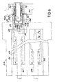
- FIG. 4 shows a part of a circuit 68 arranged inside a confinement cell 70, this part of the circuit in incorporating an ejector 72 comprising the nozzle to be replaced.
- the shape of the nozzle 74 which is integral with a cylindrical nozzle holder 76 fitted at 82 on an extension 76a also cylindrical.
- the nozzle 74, the nozzle holder 76 and the extension 76a are arranged in a bore 78a formed in the housing 78, the latter connecting the ejector 72 to the lead wall sheathed with steel 80 of the cell 70. More specifically, the housing 78 is fixed to the external steel sheath of the wall 80.
- the extension 76a has a part projecting towards the outside of the wall 80, this part being housed in normal operation in an external casing or plug 84 shown in phantom.
- This box can be fixed by any known removable means on the wall 80, and in particular by screws. It has a finger 84a which cooperates with the extension 76a in order to achieve correct orientation of the nozzle 74.
- the housing 78 comprises, at the level of the wall 80, a recess 78b open towards the outside.
- a sealing sleeve 88 is housed in this recess 78b and comprises seals 88a and 88b respectively engaging in a sealed manner the extension 76a and the housing 78.
- the dimensions of the recess 78b correspond to those of the opening 18 of the movable enclosure. More specifically, the entry of the recess 78b has a frustoconical shape extending the frustoconical end of the opening 18, the rest of the recess 78b being substantially cylindrical.
- the socket 88 also carries, at its outer end, a triple effect seal 90 complementary to the seal 22 disposed on the movable enclosure around the passage 18.
- This seal 90 normally ensures, in addition to the seal 88b, the seal between the sleeve 88 and the housing 78.
- the seal 22 then seals between the body 10 of the enclosure and the wall 80.
- a security plate 96 is normally fixed between the shutter box 84 and the box 78 to hold the bush 88 in the recess 78a and compress the seal 90.
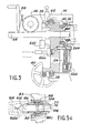
- the closure box 84 When it is desired to replace the nozzle 74, the closure box 84 is removed. The safety plate 96 and the sleeve 88 then remain in place as seen in FIG. 5a. Then introduced into the socket 88, which has for this purpose a recess 88c, a second socket 92 which cooperates in a sealed manner with the socket 88 by a gasket 92a. This introduction is carried out in a controlled manner by means of a locking ring 93 rotatably mounted on the sleeve 92, but secured to the latter in translation. This ring 93 is screwed into a thread 86 provided for this purpose at the entrance to the recess 88c. It is screwed into this thread by means of a flywheel 94, of which it is temporarily secured, for example by lugs 95.
- the assembly constituted by the extension 76a, the nozzle holder 76 and the nozzle 74 is then ready to be removed from its housing.
- a manual extractor 98 fitted with a handle 98a is then fixed at the end of the extension 76a, for example by means of a pin 100.
- a sealing sleeve 102 mounted between the sleeve 92 and the extractor 98 a sealing sleeve 102, made of flexible plastic material such as polyvinyl chloride. More specifically, the ends of the sealing sleeve 102 are housed in grooves 97 and 99 provided for this purpose in the sleeve 92 and in the extractor 98.
- Locking of the sleeve 92 is then carried out on the nozzle holder 76 by screwing the ring 93 fully into the thread 86 using the handwheel 94. As illustrated in FIG. 5c, this has the effect of bringing the fingers 104 in front of a reduced diameter portion of the recess 88c, so that these fingers move radially inward and enter a groove 106 provided for this purpose in the nose of the nozzle holder 76.
- the interlocking connection 82 between the extension 76a and the nozzle holder 76 is then disengaged from its housing, so that the extension 76a can be disengaged from the nozzle holder 76 and that the plastic sleeve 102 can be welded, then cut at 102a, as shown in FIG. 5c.
- connection sleeve 108 is put in place which also comes to be screwed into the internal thread 86.
- the shape of the sleeve 108 is determined by the shape of the recess 56 formed on the corresponding gripping head 42 of the movable enclosure, so as to subsequently allow the locking of these two parts.
- this enclosure is mounted on a carriage 110 comprising all the appropriate means allowing to carry out the positioning and the orientation of the enclosure EM with respect to the wall 80, so that the opening 18 is placed in the extension of the recess 78b and that the surface 20a is in sealed contact against the face outer wall 80.
- the carriage 110 can in particular be mounted on casters 112 allowing it to be brought closer to the wall 80 at will. Crutches (not shown) make it possible to lift the carriage from the ground when the approach is complete. Positioning can then be carried out using means 114 allowing the movable enclosure to be lowered or raised at will and means (not shown) making it possible to move the movable enclosure laterally relative to the wall 80.
- these means can be constituted by any known mechanism making it possible to carry out these functions, and in particular by systems of the threaded rod nut type making it possible to carry out precise displacements. Means of the same type also make it possible to modify the inclination of the support 115 on which the enclosure EM rests by gravity.
- means 116 also of the threaded rod nut type are provided for moving the movable enclosure EM along its axis after correct orientation and positioning of the enclosure has been achieved. It should be noted that the enclosure rests by gravity on the support 115, so that it can be transported without difficulty independently of the carriage.
- the docking surface 12a of the movable enclosure is then in sealed contact around the passage 18 with the external surface of the wall 80, under the action of the triple-effect seal 22, as shown in FIG. 6.
- the gripping head 42 of the corresponding socket is then placed in the passage 18 of the body 10.
- the end of the head 42 is also in tight contact with the sleeve 88 under the action of the triple effect seal 90.
- connection sleeve 108 is then located inside the recess 56 formed in the gripping head 42. More precisely and as illustrated in FIG. 6, the connection sleeve 108 comprises at the level of its end a groove 118 which is then opposite the movable fingers 52 of the gripping head.
- the barrel is rotated by acting on the handwheel 40, so as to bring a second cell opposite the opening 18.
- This second cell contains a nozzle 74-nozzle holder assembly 76 new, as well as two other sockets 88 and 92 and another connection sleeve 108 used to connect the assembly to the gripping head 42 contained in this cell.
- the nozzle and nozzle holder assembly is introduced into the bore 78a of the housing 78 at through the opening 18, by means of the corresponding handling rod, until the sleeve 88 comes into abutment in the recess 78b.
- the corresponding gripping head 42 is then unlocked from the connection sleeve 108 which is associated with it by removing the corresponding central pull tab 50.
- the fingers 52 are no longer then held in the groove 118 of the part 108, so that can move the mobile enclosure EM backwards by acting on the translation means 116 (FIG. 4).
- the new part finds itself in the position shown in FIG. 5c, with the exception of the sealing sleeve 102 which is then not necessary.
- the various operations described above with reference to FIGS. 5a to 5c can then be carried out in the opposite direction until the plug 84 is fitted after the nozzle has been put in place.
- the third cell has not been used, but it will be understood that it could be used in particular to carry out checks or certain repairs at the level of the nozzle to be replaced.
- the third cell could contain a false ejector that would be put in place temporarily before replacing the nozzle, in particular in order to unclog a pipe. It could also contain another new ejector or any other intervention tool such as an endoscope, a pH meter, etc. We will see another possible use of the third cell later on in the description below.
- a suitable case 122 can be placed opposite the opening 18 of the enclosure so that the end of the case sealingly engages the surface d docking 20a of the mobile enclosure.
- the nozzle 74, nozzle holder 76 contaminated inside this case is then introduced through operations similar to those which have been described previously, these operations implementing the rotation of the barrel 24 and the actuations of the rod. handling 44 and of the locking pull tab 50. This thus gives rise without difficulty to the situation shown in FIG. 7a, in which the nozzle 74 and its nozzle holder 76 are located inside the case 122.
- the shape of the recess 123 formed in the case is identical to the shape of the recess 78b and the bore 78a formed in the housing 78. As a result quence, it is easily understood that all of the contaminated parts are then either directly inside the case and isolated from the outside by the sockets 88 and 92, or protected by the plastic bag 102 for the end of the nozzle holder 76 disposed outside the case.
- the case 122 can therefore be uncoupled from the mobile enclosure, then closed by its cover 124 as shown in FIG. 7b, without any break in the confinement.
- the mobile enclosure according to the invention is intended to be used during a large number of cycles.
- the barrel 24 may require replacement after a certain number of cycles, a number which can be estimated at approximately 1000.
- the body 10 of the enclosure comprises three removable parts which are normally fixed to one another in leaktight manner.
- the body 10 comprises first of all a rear part 10a which essentially consists of the cover 16 and the corresponding end of the tubular part 14.
- This first part 10a is fixed by screws 122 to a second part 10b which is identified practically with the rest of the cylindrical part 14 of the body.
- the second part 10b is itself fixed by screws 124 on a third part 10c of the body which corresponds practically to the bottom 12.
- FIG. 9 part of a circuit 126 in which a radioactive fluid circulates.
- This circuit notably includes a filter 128 which must be changed periodically.
- this filter 128 is housed in a room 130 connecting the circuit 126 to the partition 80 'of the confinement cell containing the circuit.
- the seal is preserved by means of a plug 132 which must currently be replaced at the same time as the filter.
- the mobile enclosure EM can allow both to keep the plug 132 and to replace the filter 128 during the same intervention.
- FIG. 9 it can be seen in FIG. 9 that it suffices to fix on the plug 132 a connecting sleeve 134 provided with a groove 134a allowing it to be grasped using a grasping head comparable to the heads 42 described above. .
- the fitting 134 is put in place after removing the cover 136 which normally keeps the assembly constituted by the plug 132 and by the filter 128 in place.
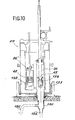
- the mobile enclosure EM As illustrated in FIG. 10, it is then possible to set up the mobile enclosure EM, for example by using a centering support 133.
- the seal is then preserved thanks to the triple seal 122 and is brought opposite the opening 18 a first cell 26 'which contains a gripping head 42 'adapted to the shape of the sleeve 134 fixed on the plug 132.
- the plug 132 is then grasped and introduced into the socket 26' in a manner comparable to that which has been described above for the nozzle-nozzle holder assembly.
- the invention is not limited to the embodiments which have just been described by way of example but covers all the variants thereof.
- the gripping head could be produced in two parts, one of which would remain in the opening of the body during transport, while the other would be brought back inside a cell under the action of the rod. corresponding handling.
- the connection between these two parts of the gripping head could be controlled simultaneously with the attachment of the head to the part to be changed by means of a central puller controlling the radial movement of a series of fingers housed in the first part of the gripping head.
- the third cell can be replaced by a plug which is applied against the first part of the gripping head housed in the opening after rotation of the barrel.
Landscapes
- Physics & Mathematics (AREA)
- Engineering & Computer Science (AREA)
- General Engineering & Computer Science (AREA)
- High Energy & Nuclear Physics (AREA)
- Manipulator (AREA)
- Supplying Of Containers To The Packaging Station (AREA)
- Pressure Vessels And Lids Thereof (AREA)
Applications Claiming Priority (2)
| Application Number | Priority Date | Filing Date | Title |
|---|---|---|---|
| FR8306028A FR2544542B1 (fr) | 1983-04-13 | 1983-04-13 | Enceinte mobile pour remplacement et le transport de pieces contaminees, et etui complementaire d'une telle enceinte |
| FR8306028 | 1983-04-13 |
Publications (2)
| Publication Number | Publication Date |
|---|---|
| EP0123598A1 true EP0123598A1 (de) | 1984-10-31 |
| EP0123598B1 EP0123598B1 (de) | 1988-02-03 |
Family
ID=9287807
Family Applications (1)
| Application Number | Title | Priority Date | Filing Date |
|---|---|---|---|
| EP84400696A Expired EP0123598B1 (de) | 1983-04-13 | 1984-04-09 | Drehbarer Transport- und Ersatzbehälter für verunreinigte Teile und Ergänzungsetui für diesen Behälter |
Country Status (6)
| Country | Link |
|---|---|
| US (1) | US4577112A (de) |
| EP (1) | EP0123598B1 (de) |
| JP (1) | JPS59197897A (de) |
| CA (1) | CA1232984A (de) |
| DE (1) | DE3469240D1 (de) |
| FR (1) | FR2544542B1 (de) |
Cited By (6)
| Publication number | Priority date | Publication date | Assignee | Title |
|---|---|---|---|---|
| FR2658947A1 (fr) * | 1990-02-28 | 1991-08-30 | Cogema | Enceinte mobile d'intervention permettant d'acceder a une installation placee dans une cellule active. |
| EP0457682A1 (de) * | 1990-05-18 | 1991-11-21 | Cogema (Compagnie Generale Des Matieres Nucleaires) | Verfahren zur Beseitigung von Verstopfungen in einer Rohrleitung für den Transport von gefährlichen Stoffen |
| FR2666442A1 (fr) * | 1990-09-05 | 1992-03-06 | Commissariat Energie Atomique | Machine de remplacement de portes d'acces a des zones irradiees, et utilisation d'une telle machine. |
| FR2670946A1 (fr) * | 1990-12-20 | 1992-06-26 | Commissariat Energie Atomique | Installation de stockage de sources radioactives. |
| FR2705090A1 (fr) * | 1993-05-10 | 1994-11-18 | Cogema | Conteneur étanche. |
| EP0463948B1 (de) * | 1990-06-25 | 1995-03-08 | Cogema (Compagnie Generale Des Matieres Nucleaires) | Verfahren zum Abbauen einer begrabenen Anlage mit Kontaminationsgefahr und Interventionskiste |
Families Citing this family (12)
| Publication number | Priority date | Publication date | Assignee | Title |
|---|---|---|---|---|
| JPS6228197U (de) * | 1985-08-05 | 1987-02-20 | ||
| FR2632763B1 (fr) * | 1988-06-08 | 1990-10-05 | Framatome Sa | Dispositif d'ouverture et de fermeture d'un filtre dans une installation nucleaire et procede de remplacement de la garniture du filtre |
| US5185757A (en) * | 1989-12-14 | 1993-02-09 | Jersey Nuclear-Avco Isotopes, Inc. | Modularized replaceable vaporizer and extractor apparatus |
| US5085410A (en) * | 1989-12-14 | 1992-02-04 | Jersey Nuclear-Avco Isotopes, Inc. | Modular processing system |
| FR2675902B1 (fr) * | 1991-04-23 | 1993-08-20 | Cogema | Installation de prelevement d'echantillons fluides dans une zone confinee. |
| US6683931B1 (en) * | 2001-12-19 | 2004-01-27 | Westinghouse Electric Company Llc | Unirradiated nuclear fuel transport system |
| KR100838659B1 (ko) | 2007-03-15 | 2008-06-16 | 황창성 | 원자력 발전소용 냉각수 차단막의 개폐장치 |
| FR3004283B1 (fr) | 2013-04-09 | 2015-04-03 | Commissariat Energie Atomique | Hotte de manutention et de confinement, application a la manutention de porte-echantillons de materiaux nucleaires, tels que des combustibles nucleaires |
| CN106816192B (zh) * | 2015-11-30 | 2018-11-02 | 江苏核电有限公司 | 一种反应堆上部组件上卡涩位置指示器取出装置 |
| WO2019092156A1 (en) | 2017-11-09 | 2019-05-16 | Rhodia Operations | Agricultural pesticide compositions |
| AU2018366265B2 (en) | 2017-11-09 | 2024-02-01 | Specialty Operations France | Aqueous compositions comprising dicamba and a built-in drift control agent |
| CN112599278B (zh) * | 2020-12-18 | 2023-08-22 | 杭州景业智能科技股份有限公司 | 一种放射性物料的远程控制自动化封装方法 |
Citations (4)
| Publication number | Priority date | Publication date | Assignee | Title |
|---|---|---|---|---|
| FR1294799A (fr) * | 1961-04-17 | 1962-06-01 | Commissariat Energie Atomique | Perfectionnements apportés aux enceintes de protection du genre de celles pour prélever des corps radioactifs dans une piscine |
| FR1386374A (fr) * | 1963-12-06 | 1965-01-22 | Commissariat Energie Atomique | Château de transport pour objets radioactifs |
| FR1586456A (de) * | 1968-08-30 | 1970-02-20 | ||
| FR2145361A1 (en) * | 1971-07-09 | 1973-02-23 | Commissariat Energie Atomique | Transit container for irradiated nuclear fuel rods - with improved heat dissipation means |
Family Cites Families (7)
| Publication number | Priority date | Publication date | Assignee | Title |
|---|---|---|---|---|
| US2514909A (en) * | 1949-01-14 | 1950-07-11 | Atomic Energy Commission | Carrier for radioactive slugs |
| FR1355690A (fr) * | 1963-02-05 | 1964-03-20 | Saint Gobain Nucleaire Soc | Dispositif pour le remplacement d'éléments filtrants contaminés dans un caisson placé en milieu radioactif |
| US3483380A (en) * | 1965-04-09 | 1969-12-09 | Gulf General Atomic Inc | Shielded cask for radioactive material |
| IT746150A (de) * | 1973-10-23 | |||
| US4149087A (en) * | 1977-05-13 | 1979-04-10 | Artemiev Lev N | Drum of storing fuel assemblies of nuclear reactor |
| DD156650A1 (de) * | 1981-02-27 | 1982-09-08 | Gerhard Langhans | Transportmagazin fuer radioaktive quellen in containern |
| JPS5973796A (ja) * | 1982-10-20 | 1984-04-26 | 株式会社東芝 | メンテナンス・キヤスク |
-
1983
- 1983-04-13 FR FR8306028A patent/FR2544542B1/fr not_active Expired
-
1984
- 1984-04-05 US US06/597,042 patent/US4577112A/en not_active Expired - Lifetime
- 1984-04-09 DE DE8484400696T patent/DE3469240D1/de not_active Expired
- 1984-04-09 EP EP84400696A patent/EP0123598B1/de not_active Expired
- 1984-04-09 CA CA000451571A patent/CA1232984A/en not_active Expired
- 1984-04-13 JP JP59074805A patent/JPS59197897A/ja active Granted
Patent Citations (4)
| Publication number | Priority date | Publication date | Assignee | Title |
|---|---|---|---|---|
| FR1294799A (fr) * | 1961-04-17 | 1962-06-01 | Commissariat Energie Atomique | Perfectionnements apportés aux enceintes de protection du genre de celles pour prélever des corps radioactifs dans une piscine |
| FR1386374A (fr) * | 1963-12-06 | 1965-01-22 | Commissariat Energie Atomique | Château de transport pour objets radioactifs |
| FR1586456A (de) * | 1968-08-30 | 1970-02-20 | ||
| FR2145361A1 (en) * | 1971-07-09 | 1973-02-23 | Commissariat Energie Atomique | Transit container for irradiated nuclear fuel rods - with improved heat dissipation means |
Cited By (10)
| Publication number | Priority date | Publication date | Assignee | Title |
|---|---|---|---|---|
| FR2658947A1 (fr) * | 1990-02-28 | 1991-08-30 | Cogema | Enceinte mobile d'intervention permettant d'acceder a une installation placee dans une cellule active. |
| EP0445033A1 (de) * | 1990-02-28 | 1991-09-04 | Cogema (Compagnie Generale Des Matieres Nucleaires) | Mobiles Arbeitsgefäss zum Einsatz in einer Anlage in einer heissen Zelle |
| US5141378A (en) * | 1990-02-28 | 1992-08-25 | Cogema-Compagnie Generale Des Matieres Nucleaires | Mobile intervention chamber providing access to an installation placed in an active cell |
| EP0457682A1 (de) * | 1990-05-18 | 1991-11-21 | Cogema (Compagnie Generale Des Matieres Nucleaires) | Verfahren zur Beseitigung von Verstopfungen in einer Rohrleitung für den Transport von gefährlichen Stoffen |
| FR2662101A1 (fr) * | 1990-05-18 | 1991-11-22 | Cogema | Procede de debouchage d'une tuyauterie vehiculant des produits dangereux. |
| EP0463948B1 (de) * | 1990-06-25 | 1995-03-08 | Cogema (Compagnie Generale Des Matieres Nucleaires) | Verfahren zum Abbauen einer begrabenen Anlage mit Kontaminationsgefahr und Interventionskiste |
| FR2666442A1 (fr) * | 1990-09-05 | 1992-03-06 | Commissariat Energie Atomique | Machine de remplacement de portes d'acces a des zones irradiees, et utilisation d'une telle machine. |
| FR2670946A1 (fr) * | 1990-12-20 | 1992-06-26 | Commissariat Energie Atomique | Installation de stockage de sources radioactives. |
| FR2705090A1 (fr) * | 1993-05-10 | 1994-11-18 | Cogema | Conteneur étanche. |
| EP0694925A1 (de) * | 1993-05-10 | 1996-01-31 | Compagnie Generale Des Matieres Nucleaires (Cogema) | Abgedichteter Behälter, und Zusammenfügung dieses Behälters und einer angepassten Halterung |
Also Published As
| Publication number | Publication date |
|---|---|
| EP0123598B1 (de) | 1988-02-03 |
| DE3469240D1 (en) | 1988-03-10 |
| FR2544542A1 (fr) | 1984-10-19 |
| US4577112A (en) | 1986-03-18 |
| FR2544542B1 (fr) | 1985-10-18 |
| CA1232984A (en) | 1988-02-16 |
| JPH0560078B2 (de) | 1993-09-01 |
| JPS59197897A (ja) | 1984-11-09 |
Similar Documents
| Publication | Publication Date | Title |
|---|---|---|
| EP0123598B1 (de) | Drehbarer Transport- und Ersatzbehälter für verunreinigte Teile und Ergänzungsetui für diesen Behälter | |
| EP3042382B1 (de) | Vorrichtung zur bereitstellung einer fluiddichten verbindung mit verbesserter betriebssicherheit | |
| EP3042380B1 (de) | Vorrichtung zur bereitstellung einer fluiddichten verbindung in zwei eingeschlossenen volumina mit vorrichtung zum halten vor der verbindung | |
| EP1463614B1 (de) | Verfahren zum anschliessen einer handhabungseinrichtung an eine hülle mit sterilem inhalt | |
| EP0418160B1 (de) | Vorrichtung zur dichten Befestigung eines austauschbaren Teiles an einem Zellenflansch und Werkzeug zur Montage einer solchen Vorrichtung | |
| EP0505269B1 (de) | Verfahren und Anlage zum Umladen von Materialien von einem verseuchten Raum in einen zweiten Raum, ohne diesen zu verseuchen | |
| EP2736638B1 (de) | Behälter zum aseptischen transfer von biopharmazeutischen produkten | |
| WO2008049879A1 (fr) | Conteneur pour le stockage de dechets radioactifs | |
| EP2736639A1 (de) | Leckdichte verbindungsvorrichtung zum aseptischen umfüllen eines biopharmazeutischen produkts zwischen einer kammer und einem behälter | |
| WO2015032712A1 (fr) | Enceinte etanche comportant un mecanisme de commande d'ouverture et de fermeture pour un dispositif de connexion etanche entre deux volumes clos | |
| FR2944380A1 (fr) | Dispositif de fixation etanche d'un organe interchangeable dans une bague d'enceinte montee sur une paroi de cellule de confinement | |
| FR2533159A1 (fr) | Dispositif de raccordement deconnectable d'une genouillere sur un bras esclave de telemanipulateur et support de deconnexion correspondant | |
| FR2747111A1 (fr) | Systeme d'accouplement pour un transfert confine d'un objet plat d'une boite de confinement vers une unite de traitement de l'objet | |
| EP3934865B1 (de) | Vorrichtung zur dichten verbindung zweier geschlossener volumina mit erhöhter sicherheit | |
| EP0445033B1 (de) | Mobiles Arbeitsgefäss zum Einsatz in einer Anlage in einer heissen Zelle | |
| EP0312460B1 (de) | Vorrichtung zur entkuppelbaren Verbindung zweier dichter Hohlräume | |
| EP2100309B1 (de) | Einrichtung zum transfer von kernbrennstoffkassetten zwischen einem transportbehälter und einer lagereinrichtung | |
| EP0185568B1 (de) | Bajonettverbindung für Handhabungsgeräte mit einer Sicherung gegen unversehenes Lösen | |
| CA1057538A (fr) | Methode de soudure de conduites immergees par manchon telescopique et dispositif de mise en oeuvre | |
| EP3691787B1 (de) | Vorrichtung mit dichter verbindung zum aseptischen transfer eines biopharmazeutischen produkts zwischen einer kammer und einem behälter | |
| FR2731895A1 (fr) | Trocart auto-bloquant a fermeture automatique | |
| EP0427628A1 (de) | Dosisleistungsmessvorrichtung in einem radioaktive Abfälle enthaltenden Transportbehälter | |
| EP2789550B1 (de) | Handhabungs- und Begrenzungshaube, Anwendung zur Handhabung von Probengefäßen für nukleares Material, insbesondere Kernbrennstoffe | |
| EP0599673A1 (de) | Verbinderhülse für abgedichtete Durchführung und dazugehörige Anordnung | |
| FR2670946A1 (fr) | Installation de stockage de sources radioactives. |
Legal Events
| Date | Code | Title | Description |
|---|---|---|---|
| PUAI | Public reference made under article 153(3) epc to a published international application that has entered the european phase |
Free format text: ORIGINAL CODE: 0009012 |
|
| AK | Designated contracting states |
Designated state(s): BE DE GB IT SE |
|
| 17P | Request for examination filed |
Effective date: 19850308 |
|
| 17Q | First examination report despatched |
Effective date: 19860305 |
|
| D17Q | First examination report despatched (deleted) | ||
| GRAA | (expected) grant |
Free format text: ORIGINAL CODE: 0009210 |
|
| RAP1 | Party data changed (applicant data changed or rights of an application transferred) |
Owner name: COMMISSARIAT A L'ENERGIE ATOMIQUE |
|
| AK | Designated contracting states |
Kind code of ref document: B1 Designated state(s): BE DE GB IT SE |
|
| REF | Corresponds to: |
Ref document number: 3469240 Country of ref document: DE Date of ref document: 19880310 |
|
| ITF | It: translation for a ep patent filed | ||
| GBT | Gb: translation of ep patent filed (gb section 77(6)(a)/1977) | ||
| PLBE | No opposition filed within time limit |
Free format text: ORIGINAL CODE: 0009261 |
|
| STAA | Information on the status of an ep patent application or granted ep patent |
Free format text: STATUS: NO OPPOSITION FILED WITHIN TIME LIMIT |
|
| 26N | No opposition filed | ||
| PGFP | Annual fee paid to national office [announced via postgrant information from national office to epo] |
Ref country code: BE Payment date: 19930330 Year of fee payment: 10 |
|
| PGFP | Annual fee paid to national office [announced via postgrant information from national office to epo] |
Ref country code: SE Payment date: 19930331 Year of fee payment: 10 |
|
| ITTA | It: last paid annual fee | ||
| PG25 | Lapsed in a contracting state [announced via postgrant information from national office to epo] |
Ref country code: SE Effective date: 19940410 |
|
| PG25 | Lapsed in a contracting state [announced via postgrant information from national office to epo] |
Ref country code: BE Effective date: 19940430 |
|
| BERE | Be: lapsed |
Owner name: COMMISSARIAT A L'ENERGIE ATOMIQUE Effective date: 19940430 |
|
| EUG | Se: european patent has lapsed |
Ref document number: 84400696.5 Effective date: 19941110 |
|
| PGFP | Annual fee paid to national office [announced via postgrant information from national office to epo] |
Ref country code: DE Payment date: 19960419 Year of fee payment: 13 |
|
| PG25 | Lapsed in a contracting state [announced via postgrant information from national office to epo] |
Ref country code: DE Free format text: LAPSE BECAUSE OF NON-PAYMENT OF DUE FEES Effective date: 19980101 |
|
| REG | Reference to a national code |
Ref country code: GB Ref legal event code: IF02 |
|
| PGFP | Annual fee paid to national office [announced via postgrant information from national office to epo] |
Ref country code: GB Payment date: 20030409 Year of fee payment: 20 |
|
| PG25 | Lapsed in a contracting state [announced via postgrant information from national office to epo] |
Ref country code: GB Free format text: LAPSE BECAUSE OF EXPIRATION OF PROTECTION Effective date: 20040408 |
|
| REG | Reference to a national code |
Ref country code: GB Ref legal event code: PE20 |