EP0427628A1 - Dosisleistungsmessvorrichtung in einem radioaktive Abfälle enthaltenden Transportbehälter - Google Patents
Dosisleistungsmessvorrichtung in einem radioaktive Abfälle enthaltenden Transportbehälter Download PDFInfo
- Publication number
- EP0427628A1 EP0427628A1 EP90403165A EP90403165A EP0427628A1 EP 0427628 A1 EP0427628 A1 EP 0427628A1 EP 90403165 A EP90403165 A EP 90403165A EP 90403165 A EP90403165 A EP 90403165A EP 0427628 A1 EP0427628 A1 EP 0427628A1
- Authority
- EP
- European Patent Office
- Prior art keywords
- tube
- door
- probe
- container
- nut
- Prior art date
- Legal status (The legal status is an assumption and is not a legal conclusion. Google has not performed a legal analysis and makes no representation as to the accuracy of the status listed.)
- Granted
Links
- 239000002901 radioactive waste Substances 0.000 title claims abstract description 15
- 239000000523 sample Substances 0.000 claims abstract description 49
- 238000005259 measurement Methods 0.000 claims abstract description 24
- 230000008878 coupling Effects 0.000 claims description 16
- 238000010168 coupling process Methods 0.000 claims description 16
- 238000005859 coupling reaction Methods 0.000 claims description 16
- 239000004020 conductor Substances 0.000 claims description 3
- 239000002699 waste material Substances 0.000 abstract description 9
- 238000003780 insertion Methods 0.000 abstract 1
- 230000037431 insertion Effects 0.000 abstract 1
- 230000000694 effects Effects 0.000 description 4
- XUIMIQQOPSSXEZ-UHFFFAOYSA-N Silicon Chemical compound [Si] XUIMIQQOPSSXEZ-UHFFFAOYSA-N 0.000 description 2
- 230000000903 blocking effect Effects 0.000 description 2
- 238000012986 modification Methods 0.000 description 2
- 230000004048 modification Effects 0.000 description 2
- 238000003032 molecular docking Methods 0.000 description 2
- 238000012958 reprocessing Methods 0.000 description 2
- 229910052710 silicon Inorganic materials 0.000 description 2
- 239000010703 silicon Substances 0.000 description 2
- 230000000295 complement effect Effects 0.000 description 1
- 239000000446 fuel Substances 0.000 description 1
- 239000003758 nuclear fuel Substances 0.000 description 1
- 230000005855 radiation Effects 0.000 description 1
Images



Classifications
-
- G—PHYSICS
- G01—MEASURING; TESTING
- G01T—MEASUREMENT OF NUCLEAR OR X-RADIATION
- G01T1/00—Measuring X-radiation, gamma radiation, corpuscular radiation, or cosmic radiation
-
- G—PHYSICS
- G21—NUCLEAR PHYSICS; NUCLEAR ENGINEERING
- G21F—PROTECTION AGAINST X-RADIATION, GAMMA RADIATION, CORPUSCULAR RADIATION OR PARTICLE BOMBARDMENT; TREATING RADIOACTIVELY CONTAMINATED MATERIAL; DECONTAMINATION ARRANGEMENTS THEREFOR
- G21F5/00—Transportable or portable shielded containers
Definitions
- the invention relates to a device for measuring the dose rate prevailing inside a transport castle in which is placed a container filled with radioactive waste.
- waste emitting ⁇ , ⁇ and ⁇ radiation such as that resulting from the reprocessing of nuclear fuels used in nuclear power plants, is generally stored on separate sites from those on which this waste is produced.
- each container is placed in containers, then each container is introduced into a transport casing connected to an access opening provided in the containment containing the waste, without breaking confinement of this enclosure. More specifically, each container is placed in a container carrier located inside the transport castle.
- Some of the existing transport castles in particular the "Padirac" castles, have a bottom pierced with a through hole. After docking of the castle on the containment, a tacky transfer is introduced through this passage hole, after its end has been coupled on a screw protruding in the center of the face of the container carrier facing the bottom of the castle . The corny then makes it possible to dock, on the interior wall of the enclosure, the container placed in the container carrier. After opening a double door, a pre-bin, usually made of cardboard, containing the waste is transferred inside the container. The double door is then closed and the container carrier, the container and the pre-bin containing the waste are brought back to the castle using the nerdy transfer.
- the subject of the invention is precisely a device making it possible to directly measure the dose rate prevailing inside a transport castle having the characteristics indicated above, so as to improve knowledge of the content of the transported castles and, consequently, storage security, as well as activity management.
- this result is obtained by means of a device for measuring the dose rate prevailing inside a transport castle containing a container carrier capable of receiving a container filled with radioactive waste, the transport comprising a bottom pierced with a through hole for a transfer tackle capable of coupling to a screw of the container carrier,
- this device being characterized in that it comprises: a probe holder comprising a tube capable of passing through the through hole, a coupling nut mounted at one end of the tube and capable of being coupled to the screw of the container carrier, an articulated door formed in the tube and suitable for occupying a closed position and an open position, and operating means accessible from the opposite end of the tube and controlling a movement of the door between its open and closed positions; - a dose rate measurement probe fixed on the door so as to be retracted into the tube when the door is in the closed position; - external measurement means connected to the dose rate measurement probe by electrical conductors passing inside the tube.
- the distance separating the measuring probe from the container is known with precision whatever the type of castle used, which ensures rigorous reproducibility of the measurements.
- the maneuvering means also preferably control the closing of an electrical supply circuit of a display system of the measuring means, when the door is in the open position. , that is to say for example when the probe is oriented at approximately 90 ° relative to the axis of the tube.
- the maneuvering means comprise a rod sliding axially inside the tube and one end of which is articulated on a rod articulated on the door and situated opposite the latter with respect to to its axis of articulation on the tube.
- the opposite end of the rod is then connected in translation to a control handle which cooperates by a screw-nut system with the end of the tube opposite to the coupling nut.
- the end of the rod opposite the link is then preferably secured to a socket which automatically closes a switch mounted at the end of the tube opposite the coupling nut and belonging to the electrical supply circuit of the display system, when the socket arrives in a front position corresponding to the open position of the door.
- the coupling nut being rotatably mounted on the probe holder, means are provided for controlling a locking in rotation of the nut relative to the probe holder.
- the reference 10 designates the wall of a confinement enclosure of which only a part is represented. This wall 10 is doubled externally by a biological protection 12.
- the confinement enclosure which contains radioactive waste, and, can in particular be located on a site for reprocessing of fuels coming from nuclear reactors.
- the wall 10 of the confinement enclosure has at least one access opening delimited by a flange 14 and normally closed by a door 16.
- the biological protection 12 also includes an opening located in front of door 16 and normally closed by a sliding door called a flyweight door 18.
- FIG. 1 also shows a transport castle 20, of the "Padirac" type mounted on a support table 22 and approached on the opening formed in the biological protection 12 of the enclosure.
- the transport castle 20 is placed on the carriage 22 so that its axis is approximately horizontal and that its end normally closed by a sliding door 24 is tightly fixed on the biological protection 12 of the enclosure and located opposite the opening formed in this biological protection.
- the doors 18 and 24 are open.
- a transfer nerdy is then coupled to a screw 28 projecting from the center of the bottom of a container carrier 30 housed in the castle 20, through a through hole 26 formed in the center of the bottom of the latter.
- the container carrier 30 is transferred as well as the container 29 which it contains, in the position illustrated in FIG. 1, in which the container 29 is sealingly approached on the opening formed in the wall. 10.
- the double- door formed by door 16 and by door 31 of the container is then opened and the waste 9 contained in a pre-bin 11, for example made of cardboard, is transferred into the container 29.
- the latter which then contains the radioactive waste filling the pre-bin 11, is then transferred to the interior of the transport castle 20 by means of the handling nerdy which actuates the container holder 30.
- the double door 16, 31 is then closed.
- a measurement is made of the dose rate prevailing inside the transport castle 20, just after the door -container 30 containing the container 29 filled with radioactive waste has been brought back into the transport castle 20.
- a measuring device is used designated generally by the reference 31 in FIG. 1 and which mainly comprises, like the 'illustrates in more detail Figure 2, a probe holder 32, a dose rate measuring probe 34 and an external measuring device 36.
- the probe holder 32 comprises a rectilinear tube 38, the outside diameter of which, identical to that of the transfer nerdy, allows it to pass through the passage hole 26 formed in the bottom of the castle 20.
- the tube 38 At its front end intended to be introduced into the inside the transport castle 20, the tube 38 carries a rotary coupling nut 40 capable of being coupled by screwing on the screw 28 projecting from the bottom of the container carrier 30.
- the tube 38 In its part adjacent to the coupling nut 40, the tube 38 comprises an opening capable of being closed by an articulated door 42 of semi-circular section.
- This door 42 is articulated on the tube 38, at its end opposite to the coupling nut 40, by an axis 44 orthogonal to the axis of the tube 38 and offset from the side of the door 42 relative to the latter.
- the hinged door 42 is extended beyond the axis 44 by a part 46 oriented obliquely towards the rear inside the tube 38.
- this part 46 is articulated by an axis 48 parallel to the axis 44 and located on the other side of the axis of the tube 38 relative to this axis 44, at the end of a rod 50 in an arc of a circle, the concavity of which is facing the axis 44.
- the opposite end of the link 50 is articulated by an axis 52 parallel to the axis 48 and disposed on the same side and approximately the same distance as the latter from the axis of the tube 38, the front end of a cylindrical rod 54.
- the latter is slidably mounted inside the tube 38 along an axis parallel to the axis of the latter and intersecting the axis 52, in lead nuts 55 filling the part corresponding to the tube 38 and used for biological protection.
- the opposite end of the rod 54 is fixed for example by means of a key 57 in a socket 56 received in a sliding manner in a bore 58 formed in a part 60 on which is fixed the rear end of the tube 38.
- the sleeve 56 is immobilized in rotation in the part 60, for example by means of a key fixed on the latter and projecting in an axial groove formed on the sleeve 56.
- the part 60 comprises a nut 64 into which is screwed a threaded rod 66 secured to an operating handle 68.
- the threaded rod 66 is extended by a cylindrical part 70 received in a bore formed axially in the socket 56.
- a headless screw 72 passing radially through the latter penetrates at its end into a groove 74 formed in the cylindrical part 70, so that the operating handle 68 is secured in translation of the sleeve 56 and, consequently, of the rod 54.
- the arrangement which has just been described makes it possible, by actuating the operating handle 68 in one or the other direction, to move the door 42 between a closed position in which this door constitutes a complementary part of the tube 38 and an open position in which the door 42 can be oriented for example at about 90 ° relative to the axis of the tube 38.
- the dose rate measuring probe 34 is fixed to the interior face of the door 42 by any suitable fixing means, such as screws.
- This measurement probe can be formed by any probe whose size is small enough to allow it to retract entirely inside the tube 38 when the door 42 is in the closed position.
- it may in particular be a silicon probe SHF IF104 SAPHYMO authorizing the measurement of a dose rate of between 0.1 rad / h and 3.104 rad / h.
- This probe is connected to the external measuring device 36 by electrical connectors 76 which run inside the tube 38, in a passage formed for this purpose in the lead nuts 55, then between the probe holder 32 and the measuring device 36.
- This measuring device is chosen so as to be compatible with the probe 34. It can therefore be constituted by any existing or future measuring device compatible with a probe whose dimensioning allows it to be retracted entirely inside the tube 38. In the case where a silicon probe is used, it can be an IF104 SAPHYMO system.
- the part 60 also supports a switch such as a micro-contact 78 which is placed in a DC power supply circuit of the display system of the external measuring device 36.
- FIG. 2 the conductors 80 of this circuit connecting the micro-contact 78 to the measuring device 36.
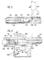
- the micro-contact 78 comprises, as best illustrated in FIG. 4, an actuating member 82 which projects through a hole 83 in the front part of the bore 58.
- the microswitch 78 By precisely positioning the microswitch 78 in the part 60, it can thus be certain that the display of the measurements is obtained for a very precise and perfectly reproducible opening position of the door 42.
- This position corresponds for example to a 90 ° orientation of the door 42 relative to the axis of the tube 38. It can vary depending on the length of the socket 56.
- the front end of the probe holder 32 is coupled to the container holder by screwing the coupling nut 40 onto the screw 28 of the container holder 30 , while the latter is placed in the castle 20 and contains the container 29 filled with Radioactive waste.
- the door 42 is in the closed position and the probe 34 is retracted inside the tube 38.
- the probe holder 32 is pressed inside the transport castle 20 over a determined distance which depends on the type of castle used, this distance being controlled by a mark formed on the outside of the tube 38.
- the operator then actuates the operating handle 68, so as to bring the door 42 carrying the probe 34 to the open position.
- the microswitch 78 automatically closes the DC power supply circuit of the display system of the apparatus 36 and the display of the dose rate begins.
- the probe holder is rotated 360 ° around the axis of the tube 38, which makes it possible to carry out a circular scan inside the castle. The presence of possible hot spots in the container is thus detected.
- the door 42 is returned to the closed position by actuating the operating handle 68 again and the probe holder 32 is brought back towards the outside of the passage hole 26, which has the effect of bringing the door back container 30 containing the container 29 filled with radioactive waste inside the castle 20.
- the coupling nut 40 is then unscrewed and the probe holder 32 is taken out of the castle.
- the passage hole 26 as well as the various doors 18 and 24 can then be closed and the castle separated from the confinement enclosure, then transported to its emptying site.
- the operations described above may be preceded by an operation for measuring these background noises, also carried out using the measuring device 31, before the container 29 is filled with radioactive waste.
- the use of the measuring device 31 according to the invention makes it possible to carry out the measurements of the dose rate inside the transport castle 20 without any modification of the structure of the latter and in a perfectly reproducible manner since the positioning of the probe inside the castle can be precisely controlled and that the distance between the probe and the container is perfectly constant.
- these means comprise a pull tab 84 supported by the tube 38, at a location diametrically opposite to the door 42, so that it can slide parallel to the axis of the tube 38, between a position before blocking the 'nut 40 and a rear position for unlocking this nut.
- the support and guiding of the pull tab 84 are ensured, at each of its ends, by screws 86 fixed on internal parts 88 integral with the tube 38. These screws 86 pass through longitudinal slots 90 formed in end parts of the pull tab 84. They have enlarged heads, wider than the slots 90, which do not protrude beyond the outer casing of the tube 38 and ensure that the pull tab 84 is held in place.
- This variant embodiment illustrated in FIG. 5 makes it possible to rotate the nut 40 independently of the rest of the probe holder, in order to fix the latter on the screw 28, and to rotate the probe holder 32 relative to the container holder 30, in order to carry out the measurement, in the same manner as in the embodiment described above. For this, the pull tab 84 is then placed in its rear position for unlocking the nut.
- Locking the nut 40 in rotation relative to the probe holder 32 obtained when the pull tab 84 occupies its position before locking the nut, allows as for him to ensure the indexing in rotation of the container carrier 30 inside the castle 20, when the container carrier retreats after the execution of the measurement.
- the invention is not limited to the embodiment which has just been described by way of example, but covers all its variants.
- the mechanism for controlling the movement of the door supporting the probe between its open and closed positions may be different from that which has been described.
- the microswitch that automatically triggers the supply current to the measurement display can in certain cases be suppressed and, when it is present, the tripping can be obtained in any position between 0 and 90 °, depending on the length of the socket 56.
Landscapes
- Physics & Mathematics (AREA)
- High Energy & Nuclear Physics (AREA)
- Engineering & Computer Science (AREA)
- General Engineering & Computer Science (AREA)
- Health & Medical Sciences (AREA)
- Life Sciences & Earth Sciences (AREA)
- General Physics & Mathematics (AREA)
- Molecular Biology (AREA)
- Spectroscopy & Molecular Physics (AREA)
- Measurement Of Radiation (AREA)
Applications Claiming Priority (2)
| Application Number | Priority Date | Filing Date | Title |
|---|---|---|---|
| FR8914702A FR2654219B1 (fr) | 1989-11-09 | 1989-11-09 | Dispositif de mesure du debit de dose dans un chateau de transport contenant des dechets radioactifs. |
| FR8914702 | 1989-11-09 |
Publications (2)
| Publication Number | Publication Date |
|---|---|
| EP0427628A1 true EP0427628A1 (de) | 1991-05-15 |
| EP0427628B1 EP0427628B1 (de) | 1995-02-15 |
Family
ID=9387231
Family Applications (1)
| Application Number | Title | Priority Date | Filing Date |
|---|---|---|---|
| EP90403165A Expired - Lifetime EP0427628B1 (de) | 1989-11-09 | 1990-11-07 | Dosisleistungsmessvorrichtung in einem radioaktive Abfälle enthaltenden Transportbehälter |
Country Status (6)
| Country | Link |
|---|---|
| US (1) | US5059797A (de) |
| EP (1) | EP0427628B1 (de) |
| JP (1) | JP2952030B2 (de) |
| KR (1) | KR910010202A (de) |
| DE (1) | DE69016929T2 (de) |
| FR (1) | FR2654219B1 (de) |
Families Citing this family (9)
| Publication number | Priority date | Publication date | Assignee | Title |
|---|---|---|---|---|
| US5274239A (en) * | 1992-07-23 | 1993-12-28 | Sunol Technologies, Inc. | Shielded dose calibration apparatus |
| US5410576A (en) * | 1994-01-10 | 1995-04-25 | Perrotti; Donald J. | Containers for disposing of low level radioactive waste and its detection |
| DE102004031386A1 (de) * | 2004-06-29 | 2006-02-02 | Infineon Technologies Ag | Prüfanordnung und Prüfverfahren zur Verifikation von Prüfprogrammen für Prüfvorrichtungen zum Test von Halbleiterbauelementen |
| KR100946316B1 (ko) | 2008-01-07 | 2010-03-08 | 한국원자력연구원 | 고방사성 시료 이송장치 |
| FR2933778B1 (fr) * | 2008-07-10 | 2012-09-28 | Commissariat Energie Atomique | Dispositif de mesure de grandeurs physiques de matieres nucleaires et procede de mise en oeuvre d'un tel dispositif. |
| FR2961606A1 (fr) * | 2010-06-21 | 2011-12-23 | Commissariat Energie Atomique | Dispositif de suivi de matiere nucleaire placee dans une boite a gants |
| US20160096135A1 (en) * | 2014-10-03 | 2016-04-07 | Camfil Usa, Inc. | Door assembly with scanning mechanism, and containment system with same |
| CN105403905B (zh) * | 2015-12-16 | 2018-03-30 | 中国工程物理研究院核物理与化学研究所 | 一种用于在线γ剂量仪的检定支架 |
| CN108583654A (zh) * | 2018-04-24 | 2018-09-28 | 中国核动力研究设计院 | 一种辐照后样品水平转运容器及转运方法 |
Citations (4)
| Publication number | Priority date | Publication date | Assignee | Title |
|---|---|---|---|---|
| FR1515024A (fr) * | 1966-10-11 | 1968-03-01 | Commissariat Energie Atomique | Château de transport de produits radioactifs |
| GB1206767A (en) * | 1966-12-20 | 1970-09-30 | Daniel Lecuyer | Improvements in or relating to containers for radioactive materials |
| EP0272944A1 (de) * | 1986-11-26 | 1988-06-29 | Framatome | Führungs- und Positionierungsrohr für Spaltzonenmessvorrichtung eines Kernreaktors |
| US4822238A (en) * | 1986-06-19 | 1989-04-18 | Westinghouse Electric Corp. | Robotic arm |
Family Cites Families (5)
| Publication number | Priority date | Publication date | Assignee | Title |
|---|---|---|---|---|
| US3643096A (en) * | 1969-02-27 | 1972-02-15 | Gen Nuclear Inc | Radioactive source shield with safe position indicator |
| JPS60131498A (ja) * | 1983-12-20 | 1985-07-13 | 関西電力株式会社 | 放射性物質収納容器 |
| US4620800A (en) * | 1984-03-08 | 1986-11-04 | Research Dynamics Incorporated | High level gamma radiation dosimeter |
| JPS62217181A (ja) * | 1986-03-19 | 1987-09-24 | Nippon Nuclear Fuel Dev Co Ltd | γ線検出器のクラツド付着防止具 |
| DE3626256A1 (de) * | 1986-08-02 | 1988-02-11 | Roehm Gmbh | Heteropolymolybdat-gemische und ihre verwendung als katalysatoren |
-
1989
- 1989-11-09 FR FR8914702A patent/FR2654219B1/fr not_active Expired - Lifetime
-
1990
- 1990-11-05 US US07/609,421 patent/US5059797A/en not_active Expired - Lifetime
- 1990-11-07 EP EP90403165A patent/EP0427628B1/de not_active Expired - Lifetime
- 1990-11-07 DE DE69016929T patent/DE69016929T2/de not_active Expired - Fee Related
- 1990-11-08 JP JP2303744A patent/JP2952030B2/ja not_active Expired - Fee Related
- 1990-11-09 KR KR1019900018222A patent/KR910010202A/ko not_active Withdrawn
Patent Citations (4)
| Publication number | Priority date | Publication date | Assignee | Title |
|---|---|---|---|---|
| FR1515024A (fr) * | 1966-10-11 | 1968-03-01 | Commissariat Energie Atomique | Château de transport de produits radioactifs |
| GB1206767A (en) * | 1966-12-20 | 1970-09-30 | Daniel Lecuyer | Improvements in or relating to containers for radioactive materials |
| US4822238A (en) * | 1986-06-19 | 1989-04-18 | Westinghouse Electric Corp. | Robotic arm |
| EP0272944A1 (de) * | 1986-11-26 | 1988-06-29 | Framatome | Führungs- und Positionierungsrohr für Spaltzonenmessvorrichtung eines Kernreaktors |
Also Published As
| Publication number | Publication date |
|---|---|
| JP2952030B2 (ja) | 1999-09-20 |
| US5059797A (en) | 1991-10-22 |
| JPH03210493A (ja) | 1991-09-13 |
| FR2654219A1 (fr) | 1991-05-10 |
| KR910010202A (ko) | 1991-06-29 |
| FR2654219B1 (fr) | 1992-02-14 |
| DE69016929T2 (de) | 1995-10-05 |
| DE69016929D1 (de) | 1995-03-23 |
| EP0427628B1 (de) | 1995-02-15 |
Similar Documents
| Publication | Publication Date | Title |
|---|---|---|
| EP0504054B1 (de) | Ventileinrichtung zur dichten Verbindung zwischen zwei Behältern sowie Behälter zur Verbindung mittels dieser Vorrichtung | |
| EP0427628B1 (de) | Dosisleistungsmessvorrichtung in einem radioaktive Abfälle enthaltenden Transportbehälter | |
| EP0505269B1 (de) | Verfahren und Anlage zum Umladen von Materialien von einem verseuchten Raum in einen zweiten Raum, ohne diesen zu verseuchen | |
| EP0123598B1 (de) | Drehbarer Transport- und Ersatzbehälter für verunreinigte Teile und Ergänzungsetui für diesen Behälter | |
| EP0064436B1 (de) | Vorrichtung zum Einführen oder Herausnehmen eines Gerätes in bzw. aus einem Dampferzeuger | |
| EP0418160A1 (de) | Vorrichtung zur dichten Befestigung eines austauschbaren Teiles an einem Zellenflansch und Werkzeug zur Montage einer solchen Vorrichtung | |
| CH407344A (fr) | Dispositif de transfert pour introduire un échantillon radioactif dans une chambre de détection et pour l'en retirer | |
| EP0649149B1 (de) | Anordnung zur Entnahme von Flüssigkeitsproben aus mit Schraubverschlüssen geschlossenen Behältern | |
| EP2092533B1 (de) | Kernbrennstoff-transporteinrichtung und verfahren zum beladen/entladen der einrichtung | |
| FR2702563A1 (fr) | Dispositif pour le prélèvement d'échantillons de sols. | |
| EP0185568B1 (de) | Bajonettverbindung für Handhabungsgeräte mit einer Sicherung gegen unversehenes Lösen | |
| CA1145174A (fr) | Dispositif de securite de largage d'une charge suspendue a un aeronef pour son transport, et charge equipee d'un tel dispositif | |
| EP0093055B1 (de) | Auskuppelbare Katapultierverhütungseinrichtung für den Regelstabantrieb eines Kernreaktors | |
| EP0151058B1 (de) | Vorrichtung zum Einbringen einer radioaktiven Quelle in ein zylindrisches Gehäuse sowie Verfahren zum Transportieren dieser Quelle in einen Transportbehälter | |
| EP0193461B1 (de) | Kalibrierverteiler von zylindrischen Elementen | |
| FR2675902A1 (fr) | Installation de prelevement d'echantillons fluides dans une zone confinee. | |
| FR2598211A1 (fr) | Dispositif d'alimentation a distance en pieces de forme cylindrique d'une machine automatique telle qu'une machine de bouchage de tubes d'un generateur de vapeur d'un reacteur nucleaire a eau sous pression | |
| EP0026142B1 (de) | Ferngesteuerte Kupplungs- und Entkupplungsvorrichtung für zwei Elemente grosser Länge, die koaxial zueinander ausgerichtet sind und sich mit ihren Stirnflächen berühren | |
| FR2749384A1 (fr) | Detecteur magnetique de proximite a point de basculement preregle | |
| EP2789550B1 (de) | Handhabungs- und Begrenzungshaube, Anwendung zur Handhabung von Probengefäßen für nukleares Material, insbesondere Kernbrennstoffe | |
| EP0600786A1 (de) | Automatische Ladevorrichtung für einen Ofen im Weltraum | |
| EP1551587A2 (de) | Verfahren und vorrichtung zum abziehen und/oder wechseln von elektroden einer schweisszange oder eines schweissgerätes | |
| FR2670946A1 (fr) | Installation de stockage de sources radioactives. | |
| EP4303887B1 (de) | Vorrichtung zur messung einer maximalen temperatur eines in einem sicherheitsbehälter einer verpackung mit einem satz radioaktiver materialien positionierten bauteils | |
| EP0211853B1 (de) | Vorrichtung zum ummanteln von brennstofftabletten |
Legal Events
| Date | Code | Title | Description |
|---|---|---|---|
| PUAI | Public reference made under article 153(3) epc to a published international application that has entered the european phase |
Free format text: ORIGINAL CODE: 0009012 |
|
| AK | Designated contracting states |
Kind code of ref document: A1 Designated state(s): BE CH DE FR GB LI NL SE |
|
| 17P | Request for examination filed |
Effective date: 19911019 |
|
| 17Q | First examination report despatched |
Effective date: 19940608 |
|
| GRAA | (expected) grant |
Free format text: ORIGINAL CODE: 0009210 |
|
| AK | Designated contracting states |
Kind code of ref document: B1 Designated state(s): BE CH DE FR GB LI NL SE |
|
| REF | Corresponds to: |
Ref document number: 69016929 Country of ref document: DE Date of ref document: 19950323 |
|
| GBT | Gb: translation of ep patent filed (gb section 77(6)(a)/1977) |
Effective date: 19950426 |
|
| PLBE | No opposition filed within time limit |
Free format text: ORIGINAL CODE: 0009261 |
|
| STAA | Information on the status of an ep patent application or granted ep patent |
Free format text: STATUS: NO OPPOSITION FILED WITHIN TIME LIMIT |
|
| 26N | No opposition filed | ||
| PGFP | Annual fee paid to national office [announced via postgrant information from national office to epo] |
Ref country code: SE Payment date: 19971024 Year of fee payment: 8 |
|
| PGFP | Annual fee paid to national office [announced via postgrant information from national office to epo] |
Ref country code: CH Payment date: 19971112 Year of fee payment: 8 |
|
| PGFP | Annual fee paid to national office [announced via postgrant information from national office to epo] |
Ref country code: NL Payment date: 19971130 Year of fee payment: 8 |
|
| PG25 | Lapsed in a contracting state [announced via postgrant information from national office to epo] |
Ref country code: SE Free format text: LAPSE BECAUSE OF NON-PAYMENT OF DUE FEES Effective date: 19981108 |
|
| PG25 | Lapsed in a contracting state [announced via postgrant information from national office to epo] |
Ref country code: CH Free format text: LAPSE BECAUSE OF NON-PAYMENT OF DUE FEES Effective date: 19981130 Ref country code: LI Free format text: LAPSE BECAUSE OF NON-PAYMENT OF DUE FEES Effective date: 19981130 |
|
| PG25 | Lapsed in a contracting state [announced via postgrant information from national office to epo] |
Ref country code: NL Free format text: LAPSE BECAUSE OF NON-PAYMENT OF DUE FEES Effective date: 19990601 |
|
| REG | Reference to a national code |
Ref country code: CH Ref legal event code: PL |
|
| EUG | Se: european patent has lapsed |
Ref document number: 90403165.5 |
|
| NLV4 | Nl: lapsed or anulled due to non-payment of the annual fee |
Effective date: 19990601 |
|
| REG | Reference to a national code |
Ref country code: GB Ref legal event code: IF02 |
|
| PGFP | Annual fee paid to national office [announced via postgrant information from national office to epo] |
Ref country code: DE Payment date: 20021125 Year of fee payment: 13 |
|
| PGFP | Annual fee paid to national office [announced via postgrant information from national office to epo] |
Ref country code: BE Payment date: 20030117 Year of fee payment: 13 |
|
| PG25 | Lapsed in a contracting state [announced via postgrant information from national office to epo] |
Ref country code: BE Free format text: LAPSE BECAUSE OF NON-PAYMENT OF DUE FEES Effective date: 20031130 |
|
| BERE | Be: lapsed |
Owner name: CIE GENERALE DES MATIERES NUCLEAIRES *COGEMA Effective date: 20031130 |
|
| PG25 | Lapsed in a contracting state [announced via postgrant information from national office to epo] |
Ref country code: DE Free format text: LAPSE BECAUSE OF NON-PAYMENT OF DUE FEES Effective date: 20040602 |
|
| PGFP | Annual fee paid to national office [announced via postgrant information from national office to epo] |
Ref country code: GB Payment date: 20061101 Year of fee payment: 17 |
|
| GBPC | Gb: european patent ceased through non-payment of renewal fee |
Effective date: 20071107 |
|
| PG25 | Lapsed in a contracting state [announced via postgrant information from national office to epo] |
Ref country code: GB Free format text: LAPSE BECAUSE OF NON-PAYMENT OF DUE FEES Effective date: 20071107 |
|
| PGFP | Annual fee paid to national office [announced via postgrant information from national office to epo] |
Ref country code: FR Payment date: 20091201 Year of fee payment: 20 |