EP0123630A1 - Vorrichtung zum Reinigen von kontinuierlichen Gegenständen in Lösungsmitteln - Google Patents
Vorrichtung zum Reinigen von kontinuierlichen Gegenständen in Lösungsmitteln Download PDFInfo
- Publication number
- EP0123630A1 EP0123630A1 EP84420040A EP84420040A EP0123630A1 EP 0123630 A1 EP0123630 A1 EP 0123630A1 EP 84420040 A EP84420040 A EP 84420040A EP 84420040 A EP84420040 A EP 84420040A EP 0123630 A1 EP0123630 A1 EP 0123630A1
- Authority
- EP
- European Patent Office
- Prior art keywords
- solvent medium
- tubular guide
- cleaning
- medium
- solvent
- Prior art date
- Legal status (The legal status is an assumption and is not a legal conclusion. Google has not performed a legal analysis and makes no representation as to the accuracy of the status listed.)
- Withdrawn
Links
- 239000002904 solvent Substances 0.000 title claims abstract description 174
- 238000004140 cleaning Methods 0.000 title claims abstract description 46
- 238000002604 ultrasonography Methods 0.000 claims abstract description 12
- 239000007788 liquid Substances 0.000 claims description 17
- 238000010438 heat treatment Methods 0.000 claims description 16
- 238000004821 distillation Methods 0.000 claims description 14
- XLYOFNOQVPJJNP-UHFFFAOYSA-N water Substances O XLYOFNOQVPJJNP-UHFFFAOYSA-N 0.000 claims description 8
- 238000005192 partition Methods 0.000 claims description 5
- 238000011084 recovery Methods 0.000 claims 2
- 238000009835 boiling Methods 0.000 description 8
- 239000003507 refrigerant Substances 0.000 description 5
- 230000008929 regeneration Effects 0.000 description 5
- 238000011069 regeneration method Methods 0.000 description 5
- 230000006866 deterioration Effects 0.000 description 4
- 239000012530 fluid Substances 0.000 description 4
- 239000000243 solution Substances 0.000 description 3
- 239000002253 acid Substances 0.000 description 2
- 238000009833 condensation Methods 0.000 description 2
- 230000005494 condensation Effects 0.000 description 2
- 230000007797 corrosion Effects 0.000 description 2
- 238000005260 corrosion Methods 0.000 description 2
- 238000006073 displacement reaction Methods 0.000 description 2
- 238000005485 electric heating Methods 0.000 description 2
- 239000013529 heat transfer fluid Substances 0.000 description 2
- 239000002689 soil Substances 0.000 description 2
- 239000012670 alkaline solution Substances 0.000 description 1
- 230000005540 biological transmission Effects 0.000 description 1
- 239000000919 ceramic Substances 0.000 description 1
- 239000002826 coolant Substances 0.000 description 1
- 239000012809 cooling fluid Substances 0.000 description 1
- 238000010908 decantation Methods 0.000 description 1
- 230000003628 erosive effect Effects 0.000 description 1
- 238000011049 filling Methods 0.000 description 1
- 238000001914 filtration Methods 0.000 description 1
- 230000004907 flux Effects 0.000 description 1
- 239000011521 glass Substances 0.000 description 1
- 230000005484 gravity Effects 0.000 description 1
- 238000007654 immersion Methods 0.000 description 1
- 229910001867 inorganic solvent Inorganic materials 0.000 description 1
- 239000003049 inorganic solvent Substances 0.000 description 1
- 239000000463 material Substances 0.000 description 1
- 239000002184 metal Substances 0.000 description 1
- 238000000034 method Methods 0.000 description 1
- 239000003960 organic solvent Substances 0.000 description 1
- 239000004033 plastic Substances 0.000 description 1
- 229910052573 porcelain Inorganic materials 0.000 description 1
- 229920006395 saturated elastomer Polymers 0.000 description 1
- 230000035939 shock Effects 0.000 description 1
- 238000002791 soaking Methods 0.000 description 1
- 229910000679 solder Inorganic materials 0.000 description 1
- 229910001220 stainless steel Inorganic materials 0.000 description 1
- 239000010935 stainless steel Substances 0.000 description 1
- 239000000126 substance Substances 0.000 description 1
- 238000004804 winding Methods 0.000 description 1
Images

Classifications
-
- B—PERFORMING OPERATIONS; TRANSPORTING
- B08—CLEANING
- B08B—CLEANING IN GENERAL; PREVENTION OF FOULING IN GENERAL
- B08B3/00—Cleaning by methods involving the use or presence of liquid or steam
- B08B3/04—Cleaning involving contact with liquid
- B08B3/10—Cleaning involving contact with liquid with additional treatment of the liquid or of the object being cleaned, e.g. by heat, by electricity or by vibration
- B08B3/12—Cleaning involving contact with liquid with additional treatment of the liquid or of the object being cleaned, e.g. by heat, by electricity or by vibration by sonic or ultrasonic vibrations
- B08B3/123—Cleaning travelling work, e.g. webs, articles on a conveyor
Definitions
- the present invention relates to an apparatus for cleaning in a solvent medium at least one continuous elongate object as well as the use of this apparatus for cleaning at least one continuous elongate object.
- continuous elongated object an object of generally elongated appearance, the longitudinal dimension of which is important with respect to the dimensions of the object in a section by a plane substantially perpendicular to the dimension longitudinal.
- the continuous elongated objects in question are not rigid, they are appreciably flexible and can be put in the form of coils or rolls.
- continuous elongated object designates both a filiform elongated object, an elongated object in the form of a ribbon or an elongated object formed of unitary elements linked together by suitable means to form a strip.
- a continuous elongated object capable of being cleaned mention may be made, as filiform elongated object of filaments, wires, cables, for example of metal, from which all traces of soiling must be removed; as elongated object in the form of a ribbon, mention may be made of metallic ribbons, magnetic tapes, photographic films; and as an elongated object formed of unitary elements linked together, there may be mentioned electronic components soldered on printed circuits (from which all traces of solder flux must be eliminated) which are placed side by side and connected for example by a support. to form a slender object having the appearance of a band.
- solvent medium means a liquid which contains at least one substance capable of putting at least one other in solution.
- the solvent medium can for example contain at least one organic and / or inorganic solvent or else be an alkaline or acid solution.
- Apparatuses for cleaning such objects proceed generally by soaking the object in the solvent medium.
- These devices most often consist of a tank, open at its upper part, provided in the vicinity of its opening with an inlet ramp and an outlet ramp.
- the tank contains a liquid solvent medium chosen for its ability to dissolve the dirt present on the object.
- the solvent medium is generally heated, sometimes to boiling point, and often subjected to the action of ultrasound until cavitation, which promotes the removal of non-soluble dirt in the solvent medium.
- the liquid solvent medium is sometimes surmounted by a zone of hot saturated vapor of the solvent medium and means of condensation are provided at the upper part of the tank to prevent the exit of the vapor out of the tank.
- the elongated object to be cleaned is moved in the tank in such a way that it successively crosses the vapor zone, the solvent medium, and again, the steam zone.
- the object undergoes a preheating, by condensation of the vapor on its surface, which avoids a thermal shock during its immersion in the hot solvent medium, and by trickling of oondensate there occurs a pre-cleaning of the object.
- the displacement of the object in the tank is generally ensured by the exercise of a traction force on the object by means. which can be means for winding the object.
- the object moves in the tank according to a trajectory and at a speed such that the object's residence time in the solvent medium is sufficient to ensure proper cleaning of the object.
- the object moves along a free path between the access ramp and the exit ramp and nothing prevents, in the event of the object moving speed too high, this that it follows too short a path in the solvent medium or even emerges from it.
- Such an apparatus avoids any untimely emergence of the elongated object from the solvent medium, however the rollers significantly increase the risks of deterioration of the elongated object. These deteriorations even go, in the case of cleaning electronic circuits, to the tearing of the components.
- An object of the invention is an apparatus for cleaning in a solvent medium of a continuous slender object, which avoids any untimely emersion of the object out of the solvent medium while preventing any deterioration of the object.
- an apparatus for cleaning in a solvent medium at least one continuous elongated object characterized in that it comprises ramps for entering and leaving said object, means for guiding the elongated object constituted by a tubular guide open at its ends, said object moving inside said tubular guide along a path imposed in the form of a continuous curve, said tubular guide being provided in the vicinity of one end of means for entering its own solvent medium and in the vicinity of the other end of means for removing dirty solvent medium in such a way that the solvent medium circulates in the tubular guide in contact with the elongated object in the opposite direction to the movement of the object in the tubular guide and the means to subject the solvent medium to ultrasound.
- the continuous curve constituting the trajectory of the object is such that its concavity is turned towards the surface of the solvent medium and it is advantageously plane and preferably located in a plane perpendicular to said surface.
- the tubular guides are shaped in such a way that they make it possible to impose on the object a trajectory in the form of a continuous curve whose concavity is turned towards the surface of the solvent medium.
- the tubular guides are made of a material which is well resistant to corrosion by the solvent medium which may be, for example a fluorinated solvent or an acid solution or an alkaline solution, to wear due to friction of the object, as well as erosion due to cavitation of the solvent medium when it is subjected to the action of ultrasound.
- the solvent medium which may be, for example a fluorinated solvent or an acid solution or an alkaline solution, to wear due to friction of the object, as well as erosion due to cavitation of the solvent medium when it is subjected to the action of ultrasound.
- the tubular guides can be produced, for example: plastic, stainless steel, glass, ceramic, porcelain, etc.
- the tubular guides can have a section through a plane perpendicular to the direction of movement, of anyone shape, preferably the section is chosen in a shape such that it prevents any lateral movement of the object.
- Such a tubular guide can be for example of square, rectangular, circular, elliptical section.
- the dirty solvent medium leaving the tubular guide can be directed to a regeneration device, for example by distillation, and reintroduced clean into the tubular guide by the means of Entrance.
- the apparatus comprises a tank open at its upper part and containing a liquid medium and the tubular guide is partly immersed in the liquid medium, so that its ends are located above from the surface of the liquid medium in the tank.
- the liquid medium contained in the tank is solvent medium and the means for entering clean solvent medium into the tubular guide are at an altitude higher than that of the means for leaving dirty solvent medium and located above the surface. middle solvent.
- the dirty solvent medium can flow directly into the tank.
- the means for subjecting the solvent medium to ultrasound can be constituted by emitters immersed in the solvent medium itself.
- the ultrasonic emitters are fixed to the wall of the tubular guide or of the tank according to the method of fixing a piezoelectric transducer on a thin wall which is the subject of French patent 1,526,179.
- Ultrasound is transmitted to the solvent medium either directly or through the liquid medium.
- the apparatus according to the invention is such that it includes means for heating the solvent medium.
- the means for heating the solvent medium can be, for example, electric heating means or means for heating by circulation of a heat transfer fluid.
- Electric heating means can, for example, be constituted by resistors immersed in the solvent medium or fixed to the wall of the tubular guide or of the tank.
- Heating means by circulation of a heat transfer fluid may, for example, be constituted by a coil immersed in the solvent medium or a double jacket around a part of the wall of the tubular guide or of the tank.
- the apparatus is such that it is provided with means for condensing the vapors of said solvent medium.
- the means for condensing the vapors of the solvent medium can be, for example, a coil traversed by a cooling fluid, such as water, placed on the inner face from the wall of the tubular guide in the vicinity of its ends or else a sleeve traversed by a refrigerant fluid fixed on the external face of the wall of the tubular guide in the vicinity of its ends.
- a cooling fluid such as water
- the means for condensing the vapors of the solvent medium can be, for example, a coil traversed by a fluid refrigerant, such as water, placed on the inner face of the wall of the tank in the vicinity of its opening or a double jacket traversed by a refrigerant fluid fixed externally to the side wall of the tank in the vicinity of its opening.
- a fluid refrigerant such as water
- the means for entering the clean solvent medium are connected to means for recovering the condensate of the vapors of said solvent medium.
- the apparatus according to the invention further comprises, between the means for recovering the condensate from the vapors of the solvent medium and the means for entering the clean solvent medium, a water separator device and a device for heating the condensate.
- the apparatus In order to have a sufficient quantity of vapor from the solvent medium it is advantageous for the apparatus to be such that the tank containing the solvent medium consists of a cleaning compartment in which the tubular guide is partly immersed in the solvent medium and a solvent medium distillation compartment provided with means for heating the solvent medium, the partition between said cleaning compartment and said distillation compartment comprising an overflow threshold and an opening for supplying the vapors of the solvent medium into said cleaning compartment.
- An apparatus according to the invention for simultaneously cleaning several objects is also part of the invention.
- Such an apparatus comprises several entry and exit ramps for objects and several tubular guides placed side by side with no common point or joined together, two neighboring tubular guides having a common wall portion.
- the apparatus, object of the invention can be used to clean at least one elongated, threadlike object such as a wire, a filament, a cable.
- It can also be used to clean at least one elongated strip-shaped object.
- the apparatus according to the invention is more particularly intended to be used for cleaning at least one elongated object formed of unitary elements linked together, for example by a support, to form a band, such unitary elements can be components electronic soldered on printed circuits.
- the apparatus (10) for cleaning in a solvent medium an elongate object according to the embodiment shown in FIG. 1 comprises an inlet ramp (6), an outlet ramp (7) and a drive device (8) of the elongated object (11) constituted for example by two rollers driven in rotation to move the object according to the arrow.
- the guide means consist of a tubular guide (12) open at its two ends inside which the object (11) moves along a path imposed in the form of a continuous curve.
- the tubular guide (12) is held in place by fixing lugs (23) inside a box (24).
- the tubular guide (12) comprises in the vicinity of one end of the inlet means (21) of clean solvent medium and in the vicinity of the other end of the outlet means (22) of dirty solvent medium in such a way that the medium solvent (2) flows in the tubular guide (12) in contact with the elongated object (11) in the opposite direction of the movement of the object (11).
- the inlet means (15) can be connected to a source of clean solvent medium and the outlet means (16) of dirty solvent medium are then connected to a tank for recovering the dirty solvent medium in view of a subsequent regeneration.
- the dirty solvent medium is directed directly to a regeneration device (25), for example by distillation or by filtration, and the clean solvent medium leaving this device is reintroduced into the tubular guide (12) by the inlet means. (21). It therefore creates in the tubular guide (12) a circulation of the solvent medium in contact with the elongated object (11) in the opposite direction of the movement of the object in the tubular guide (12).
- the tubular guide (12) is provided on a part of its outer surface with heating means (4) making it possible to bring the solvent medium (2) to a boil and to create two vapor zones (18, 19).
- the tubular guide (12) is provided at each of its ends with a sleeve (20) comprising means (5) for condensing the vapors of the solvent medium (2).
- Ultrasonic emitters (31) are attached to the wall of the tubular guide (12).
- Figure 2 shows the position of the elongated object (11) in the tubular guide (12), the elongated object (11) which is cleaned is here formed of electronic components (26) soldered on printed circuits (27) which are connected by a support (28) to form a band.
- the edges (29, 30) of the support (28) abut on the inner surface of the tubular guide (12) when a tensile force is exerted by means of the rollers of the drive device (8).
- the same solvent medium can circulate, the ends of the tubular guides situated on the side of the inlet and / or outlet ramps can open into the same sleeve comprising condensing means.
- each tubular guide having its solvent inlet and outlet means connected to different regeneration devices.
- the heating means (4) of the solvent medium (2) are put into operation until the solvent medium (2) is boiling and two vapor zones (18, 19) of the solvent medium form above the surface (14) of the solvent medium (2).
- the circulation of refrigerant fluid is established in the coils (5) located in the vicinity of the ends of the tubular guide (12) in order to prevent the vapor of the solvent medium from escaping.
- the solvent medium (2) is circulated in the tubular guide (12), from the inlet means (21) to the outlet means (22).
- the ultrasonic transmitters (31) are put into service.
- the elongate object (11) is introduced successively into the inlet ramp (6), into the tubular guide (12), into the outlet ramp (7) and between the rollers of the drive device (8).
- the elongated object is successively moved through a first vapor zone (18), in the solvent medium (2), in a second vapor zone (19 ) of the solvent medium, along a path imposed in the form of a continuous curve.
- the elongated object (11) When passing through the first vapor zone (18), the elongated object (11) is preheated and pre-cleaned. When passing through the solvent medium (2) the dirt is dissolved and / or peeled off and the elongated object (11) is rinsed by the solvent medium (2) which moves in the opposite direction. during the crossing of the second vapor zone (19) the elongated object (11) is rinsed by trickling of the condensate of the vapor.
- the object is successively moved through a first vapor zone (18) of the solvent medium, the hot solvent medium (2), a second vapor zone (19 ), according to a trajectory imposed in the form of a continuous curve and clean and hot solvent medium is brought which is circulated continuously in contact with the elongate object in the opposite direction of the object's movement.
- the tubular guide (12) can be partly immersed in a liquid medium so that the ends of the tubular guide (12) are located above the level of the liquid medium.
- the liquid medium is then contained in a tank placed in the box (24), the emitters (31) being fixed to the wall of the tank.
- the ultrasound emitted by the emitters is transmitted by the liquid medium to the solvent medium (2) after passing through the wall of the tubular guide (12).
- the solvent medium (2) contained in the tubular guide (12) is heated but not brought to boiling, the boiling bringing a hinders the transmission of ultrasound.
- An elongated object cleaned using an apparatus according to this embodiment is both subjected to the cleaning action of the hot solvent medium and to the cleaning action of ultrasound.
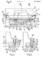
- FIGS. 3, 4 and 5 A preferred embodiment of the cleaning device in a solvent medium for a long object, object of the invention is shown in FIGS. 3, 4 and 5.
- the apparatus (10) for cleaning a slender object (11), object of the invention comprises a tank (3) containing the solvent medium (2), open at its upper part and provided in the vicinity of its opening with means for condensing the vapors of the solvent medium, constituted by a coil (5) traversed by a refrigerant.
- the tank (3) of the device according to this embodiment consists of two compartments (29, 30) which are a cleaning compartment (29) and a distillation compartment (30).
- the cleaning compartment (29) is substantially parallelepipedic, and its bottom is fitted with transmitters (31).
- a tubular guide (12) In the cleaning compartment (29) is partially submerged in the solvent medium (2), a tubular guide (12), open at its ends, inside which the object moves.
- the tubular guide (12) is provided in the vicinity of one end of inlet means (21) of clean solvent medium and at the other end of outlet means (22) of dirty solvent medium, for circulating the solvent medium (2) in contact with the object (11) in the opposite direction to the movement of the object.
- the tubular guide (12) is partly immersed in the solvent medium (2) contained in the tank (3) so that its ends, the means of the inlet (21) of clean solvent medium and the outlet means (22) of dirty solvent medium, are located above the surface (14) of the solvent medium (2), and that the inlet means (21) of clean solvent medium are located at an altitude higher than that of the means (-22) for removing the dirty solvent medium, so that the solvent medium flows by gravity from one end to the other of the tubular guide (12) in traveling in contact with the elongate object (11) in the opposite direction of its movement.
- the dirty solvent medium flows directly into the cleaning compartment (29).
- the distillation compartment (30) is provided with heating means (4), for example electric, making it possible to bring the solvent medium (2) to its boiling point.
- the partition (32) separating the cleaning compartment (29) and the distillation compartment has an overflow threshold (33) which allows the solvent medium (2) contained in the cleaning compartment (29) to flow in the distillation compartment (30) and an opening (34) which allows the solvent-medium vapors, generated by the boiling of the solvent medium (2) contained in the distillation compartment (30), to enter the cleaning compartment (29) and create a vapor zone (17) of the solvent medium above the level (14) of the solvent medium (2).
- the partition (32) can have a uniform height equal to the height of the overflow threshold.
- a conduit (36) conveys the condensate recovered to a water separating device (37) which can be, for example a separating device by decantation, or a cartridge filled with a product having the ability to absorb water while letting the solvent medium pass.
- a conduit (38) routes the clean solvent medium to the inlet means (21) of the tubular guide (12).
- the heating device can be constituted by the conduit (38), for example put in helical form and placed within the vapor zone (17) of the solvent medium.
- the device also includes, like the device according to the embodiments described above, an entry ramp (6), an exit ramp (7) and a drive device (8) for the elongated object. (11).
- the device can also optionally be provided with a cover (39), advantageously transparent.
- the heating means (4) of the solvent medium (2) contained in the distillation compartment are put into operation. (30) until the solvent medium is boiling and the vapor of solvent medium passes through the opening (34) of the partition (32) and creates the vapor zone (17) above the surface ( 14) of the solvent medium (2) placed in the cleaning compartment (29).
- the circulation of coolant is established in the coil (5) located near the opening of the tank (3) of the apparatus, in order to condense the vapors of the solvent medium by means of the coil (5) and prevent them from escaping out of the tank (3) of the appliance (10).
- the condensate recovered in the chute (35) is conveyed by the conduit (36) to the water separating device (37), the water-free condensate, which is clean solvent medium, leaves the device (37) through the conduit (38) and is routed to the inlet means (21) after being heated in the helical conduit (39).
- the solvent medium will therefore be circulated in the tubular guide (12) continuously, from the inlet means (21) to the outlet means (22), in the opposite direction of the movement of the object (11).
- the solvent medium leaving the tubular guide (12) by the outlet means (21) arrives in the cleaning compartment (29), the solvent medium escapes by overflowing above the threshold (33) and falls into the compartment distillation (30) where it is brought to a boil.
- the ultrasonic transmitters (31) are put into service.
- the elongated object (11) is introduced successively into the inlet ramp (6), into the tubular guide (12), into the outlet ramp (7) and then between the drive rollers (8).
- the slender object is successively moved through a first vapor zone [between the inlet ramp (6) and the surface of the solvent medium (2) in the tubular guide (12)], in the solvent medium (2), in a second vapor zone of the solvent medium [between the surface of the solvent medium (2) in the tubular guide (12) and the outlet ramp (7) J.
- the elongated object (11) When crossing the first vapor zone, the elongated object (11) is preheated and pre-cleaned. When passing through the solvent medium (2) the elongated object (11) is subjected to the cleaning action of the solvent medium and the non-soluble soils in it are removed by the action of the solvent medium cavitated by the ultrasound. The elongated object (11) is rinsed by the solvent medium (2) which moves in the opposite direction to the movement of the object (11). when passing through the second steam zone the object (11) is rinsed by trickling steam condensate.
- the device for cleaning at least one elongated object according to the invention has numerous advantages compared to the devices according to the prior art.
- the means for guiding the object along a continuous curve make it possible to introduce the object into the device with greater ease than in devices equipped with rollers because, in these, the operator must manually place the object around each pebble.
- guide means constituted by a tubular guide it suffices to introduce the elongated object at one end and to push it little by little towards the inside of the guide so that it reaches the other end without risk. attachment and without manual operator intervention in the solvent medium.
- the device also has the advantage of avoiding the risk of deterioration of the object to be cleaned.
- An important advantage of the apparatus according to the invention lies in the low consumption of solvent medium, while making it possible to obtain a good quality cleaning of the object, this is due to the circulation of clean solvent medium in the opposite direction from the displacement of the object which allows rinsing of the object with clean solvent just before it leaves the solvent medium.
- the apparatus also makes it possible, according to certain embodiments, to use only a small volume of solvent medium since it is sufficient for the tubular guide to contain solvent medium.
- the device Due to its low solvent consumption, the device also has the advantage of reducing the problems of pollution and solvent regeneration.
Landscapes
- Cleaning By Liquid Or Steam (AREA)
Applications Claiming Priority (2)
| Application Number | Priority Date | Filing Date | Title |
|---|---|---|---|
| FR8305649A FR2543459B1 (fr) | 1983-04-01 | 1983-04-01 | Procede de nettoyage en milieu solvant d'au moins un objet longiligne continu, appareil pour la mise en oeuvre du procede et emploi dudit appareil |
| FR8305649 | 1983-04-01 |
Publications (1)
| Publication Number | Publication Date |
|---|---|
| EP0123630A1 true EP0123630A1 (de) | 1984-10-31 |
Family
ID=9287589
Family Applications (1)
| Application Number | Title | Priority Date | Filing Date |
|---|---|---|---|
| EP84420040A Withdrawn EP0123630A1 (de) | 1983-04-01 | 1984-03-08 | Vorrichtung zum Reinigen von kontinuierlichen Gegenständen in Lösungsmitteln |
Country Status (3)
| Country | Link |
|---|---|
| US (1) | US4605027A (de) |
| EP (1) | EP0123630A1 (de) |
| FR (1) | FR2543459B1 (de) |
Cited By (5)
| Publication number | Priority date | Publication date | Assignee | Title |
|---|---|---|---|---|
| FR2607347A1 (fr) * | 1986-11-21 | 1988-05-27 | Teledyne Ind | Appareil, installation et procede de nettoyage de cartes de circuit imprime |
| FR2614562A1 (fr) * | 1987-04-29 | 1988-11-04 | Outillages Scient Lab | Machine de nettoyage notamment pour sous-ensembles electroniques |
| FR2653684A1 (en) * | 1989-10-27 | 1991-05-03 | Osl Technologies | Machine for cleaning with the aid of a solvent |
| RU2238162C1 (ru) * | 2003-02-11 | 2004-10-20 | Общество с ограниченной ответственностью "Александра-Плюс" | Способ очистки проволоки или ленты и устройство для его осуществления |
| CN103861840A (zh) * | 2014-03-12 | 2014-06-18 | 张家港市港威超声电子有限公司 | 超声波矿浆侵取机 |
Families Citing this family (10)
| Publication number | Priority date | Publication date | Assignee | Title |
|---|---|---|---|---|
| JPS63229185A (ja) * | 1987-03-18 | 1988-09-26 | 三井・デユポンフロロケミカル株式会社 | 洗浄方法及び洗浄装置 |
| US4788992A (en) * | 1987-04-28 | 1988-12-06 | Lewis Corporation | Ultrasonic strip cleaning apparatus |
| US5090430A (en) * | 1990-02-02 | 1992-02-25 | Agape Enterprises, Inc. | Ultrasonic cleaning system for fluorescent light diffuser lens |
| US5072478A (en) * | 1990-02-08 | 1991-12-17 | Wagner Richard N | Vertical blind cleaning machine |
| US5246501A (en) * | 1990-12-07 | 1993-09-21 | Alliedsignal Inc. | Flash drying treatment of solvent from workpieces |
| DE4316144A1 (de) * | 1993-05-14 | 1994-11-17 | Siemens Ag | Verfahren und Einrichtung zur Reinigung eines gezogenen Drahtes |
| DE19706007C1 (de) * | 1997-02-10 | 1998-07-09 | Hielscher Gmbh | Verfahren zum Reinigen von fadenförmigen Erzeugnissen, insbesondere von Drähten und Profilen |
| US20030124853A1 (en) * | 1998-06-25 | 2003-07-03 | Mitsubishi Materials Silicon Corporation | Anisotropic etching method and apparatus |
| US8839804B2 (en) * | 2009-01-22 | 2014-09-23 | Electric Power Research Institute, Inc. | Conductor cleaning system |
| US9101966B2 (en) * | 2010-08-23 | 2015-08-11 | International Business Machines Corporation | Cleaning magnetic tape |
Citations (2)
| Publication number | Priority date | Publication date | Assignee | Title |
|---|---|---|---|---|
| US2947595A (en) * | 1955-01-24 | 1960-08-02 | Celanese Corp | Treatment of filamentary materials |
| FR2311599A1 (fr) * | 1975-05-21 | 1976-12-17 | Skf Ind Trading & Dev | Dispositif pour le nettoyage de pieces mecaniques, notamment de paliers |
Family Cites Families (7)
| Publication number | Priority date | Publication date | Assignee | Title |
|---|---|---|---|---|
| US2270642A (en) * | 1935-02-08 | 1942-01-20 | Budd Induction Heating Inc | Cleaning and degreasing system |
| US2153577A (en) * | 1935-03-07 | 1939-04-11 | Du Pont | Process of degreasing |
| US3099584A (en) * | 1960-08-08 | 1963-07-30 | Eastman Kodak Co | Method for the removal of magnetic sound track from movie film |
| DE2362011A1 (de) * | 1973-12-13 | 1975-06-19 | Boco Waeschedienst Ernst Rethw | Verfahren und vorrichtung zum reinigen von waesche-und bekleidungsstuecken |
| US3968013A (en) * | 1974-09-12 | 1976-07-06 | Hollis Engineering, Inc. | System for cleaning work pieces with solvent |
| FR2296025A1 (fr) * | 1974-12-27 | 1976-07-23 | Cucco Georges | Machine et procede pour le degraissage de pieces avec un solvant |
| NL7605826A (nl) * | 1975-06-02 | 1976-12-06 | Elektrokemiska Ab | Werkwijze voor het verwarmen van het oplosmid- delbad van een ontvettingsinrichting. |
-
1983
- 1983-04-01 FR FR8305649A patent/FR2543459B1/fr not_active Expired
-
1984
- 1984-03-08 EP EP84420040A patent/EP0123630A1/de not_active Withdrawn
- 1984-04-02 US US06/595,824 patent/US4605027A/en not_active Expired - Fee Related
Patent Citations (2)
| Publication number | Priority date | Publication date | Assignee | Title |
|---|---|---|---|---|
| US2947595A (en) * | 1955-01-24 | 1960-08-02 | Celanese Corp | Treatment of filamentary materials |
| FR2311599A1 (fr) * | 1975-05-21 | 1976-12-17 | Skf Ind Trading & Dev | Dispositif pour le nettoyage de pieces mecaniques, notamment de paliers |
Cited By (7)
| Publication number | Priority date | Publication date | Assignee | Title |
|---|---|---|---|---|
| FR2607347A1 (fr) * | 1986-11-21 | 1988-05-27 | Teledyne Ind | Appareil, installation et procede de nettoyage de cartes de circuit imprime |
| FR2614562A1 (fr) * | 1987-04-29 | 1988-11-04 | Outillages Scient Lab | Machine de nettoyage notamment pour sous-ensembles electroniques |
| EP0293312A1 (de) * | 1987-04-29 | 1988-11-30 | O.S.L. S.A. | Waschanlage, insbesondere für elektronische Teilbaugruppen |
| FR2653684A1 (en) * | 1989-10-27 | 1991-05-03 | Osl Technologies | Machine for cleaning with the aid of a solvent |
| RU2238162C1 (ru) * | 2003-02-11 | 2004-10-20 | Общество с ограниченной ответственностью "Александра-Плюс" | Способ очистки проволоки или ленты и устройство для его осуществления |
| CN103861840A (zh) * | 2014-03-12 | 2014-06-18 | 张家港市港威超声电子有限公司 | 超声波矿浆侵取机 |
| CN103861840B (zh) * | 2014-03-12 | 2017-04-19 | 张家港市港威超声电子有限公司 | 超声波矿浆浸取机 |
Also Published As
| Publication number | Publication date |
|---|---|
| FR2543459A1 (fr) | 1984-10-05 |
| US4605027A (en) | 1986-08-12 |
| FR2543459B1 (fr) | 1986-07-11 |
Similar Documents
| Publication | Publication Date | Title |
|---|---|---|
| EP0123630A1 (de) | Vorrichtung zum Reinigen von kontinuierlichen Gegenständen in Lösungsmitteln | |
| WO1998054440A1 (fr) | Procede et dispositif pour deboucher un puits ou une canalisation obstrues par des hydrates de gaz | |
| US4375992A (en) | Apparatus and method for cleaning recorded discs | |
| CH653453A5 (fr) | Procede et machine pour le developpement de plaques de tous types a couche photosensible. | |
| EP0369851A1 (de) | Reinigungsvorrichtung für ein Rohr in dem ein Fluid zirkuliert | |
| EP1337681A1 (de) | Vorrichtung zur tauchbeschichtung eines metallstreifens | |
| FR2571750A1 (fr) | Machine a laver le linge ou autres comportant un dispositif de la mesure de la turbidite de l'eau | |
| CA1292437C (fr) | Dispositif de nettoyage a bande rotative sans fin, notamment pour le nettoyage d'une bande transporteuse ou de surfaces de sustentation d'objects | |
| EP0141941A1 (de) | Vorrichtung zum Niederschlagen einer polykristallinen Siliziumschicht auf einem Kohlenstoffband | |
| FR2816638A1 (fr) | Installation de revetement au trempe d'une bande metallique notamment d'une bande d'acier | |
| FR2530326A1 (fr) | Bloc recuperateur de calories et lave-vaisselle muni d'un tel bloc | |
| EP0293312A1 (de) | Waschanlage, insbesondere für elektronische Teilbaugruppen | |
| US2104102A (en) | Method for degreasing | |
| FR2498210A1 (fr) | Appareil et procede de placage electrolytique, et appareil de rincage a contre-courant correspondant | |
| FR2476614A1 (fr) | Dispositif de transport pour recipients en verre, notamment des bouteilles | |
| FR2776542A1 (fr) | Appareil de nettoyage par ultrasons | |
| FR2541091A1 (fr) | Procede de nettoyage notamment destine a des produits alimentaires ainsi que dispositif permettant la mise en oeuvre de ce procede | |
| CN113235034B (zh) | 一种铜线加工用的镀锡装置 | |
| FR2721235A1 (fr) | Installation de traitement, notamment pour le décapage d'une bande métallique. | |
| EP0157057B1 (de) | Verfahren zum nacheinander Galvanisieren eines Metallbandes mit zwei verschiedenen Metallüberzügen | |
| US4367030A (en) | Photographic developer-printer assembly, and a conveying roller unit therefor | |
| CH540771A (fr) | Procédé pour refroidir un extrudat tubulaire et installation pour la mise en oeuvre de ce procédé | |
| US5786014A (en) | Capacity caustic peeler system | |
| EP0769248B1 (de) | Vorrichtung zum Waschen von Fischen und Fisch-Träger für diese Vorrichtung | |
| FR2784998A1 (fr) | Installation de decapage d'une bande metallique |
Legal Events
| Date | Code | Title | Description |
|---|---|---|---|
| PUAI | Public reference made under article 153(3) epc to a published international application that has entered the european phase |
Free format text: ORIGINAL CODE: 0009012 |
|
| AK | Designated contracting states |
Designated state(s): BE CH DE GB IT LI LU NL |
|
| 17P | Request for examination filed |
Effective date: 19850402 |
|
| 17Q | First examination report despatched |
Effective date: 19860714 |
|
| D17Q | First examination report despatched (deleted) | ||
| STAA | Information on the status of an ep patent application or granted ep patent |
Free format text: STATUS: THE APPLICATION IS DEEMED TO BE WITHDRAWN |
|
| 18D | Application deemed to be withdrawn |
Effective date: 19890526 |
|
| RIN1 | Information on inventor provided before grant (corrected) |
Inventor name: DALLOT, MARIO |