EP0123694A1 - Assemblage de tete rotative - Google Patents
Assemblage de tete rotative Download PDFInfo
- Publication number
- EP0123694A1 EP0123694A1 EP83902128A EP83902128A EP0123694A1 EP 0123694 A1 EP0123694 A1 EP 0123694A1 EP 83902128 A EP83902128 A EP 83902128A EP 83902128 A EP83902128 A EP 83902128A EP 0123694 A1 EP0123694 A1 EP 0123694A1
- Authority
- EP
- European Patent Office
- Prior art keywords
- tape
- cylinder
- head assembly
- rotary
- rotary head
- Prior art date
- Legal status (The legal status is an assumption and is not a legal conclusion. Google has not performed a legal analysis and makes no representation as to the accuracy of the status listed.)
- Granted
Links
Images


Classifications
-
- G—PHYSICS
- G11—INFORMATION STORAGE
- G11B—INFORMATION STORAGE BASED ON RELATIVE MOVEMENT BETWEEN RECORD CARRIER AND TRANSDUCER
- G11B15/00—Driving, starting or stopping record carriers of filamentary or web form; Driving both such record carriers and heads; Guiding such record carriers or containers therefor; Control thereof; Control of operating function
- G11B15/60—Guiding record carrier
- G11B15/61—Guiding record carrier on drum, e.g. drum containing rotating heads
Definitions
- This invention relates to a rotary head assembly of a video tape recorder (hereinafter called VTR), and is more particularly intended to present a rotary head assembly capable of recording and reproducing picture images of high quality at high reliability, by lifting the tape up from the cylinder with the dynamic pressure built up by pump-out type spiral grooves so as to lessen the tape running load, tape damage and wear of the cylinder itself due to sliding and friction of the tape and also to stabilize the tape running.
- VTR video tape recorder
- a rotary head assembly of a VTR is generally composed of an upper rotary cylinder 2 and a lower fixed cylinder 3 as shown in FIG. 1, and a magnetic tape runs at a constant speed being helically wound around the rotary head assembly of about 180°.
- Numeral 4 refers to a step part (called • lead hereinafter) which guides the running position of the tape in its widthwise direction.
- a video head 5 is fixed to the upper rotary cylinder 2 and rotates at high speed (1800 rpm in the VHS system V T R) to record and reproduce picture signals on the magnetic tape.
- Numerals 6, 7, 8, 9 are tape guide posts.
- FIG. 2 is a schematic model representing a sectional view of a conventional rotary head assembly and the behavior of magentic tape 1 on it. Since the upper rotary cylinder 2 rotates at high speed, an air film is formed between the tape 1 and the outer circumference of the upper rotary cylinder 3 due to inclusion of air, so that the tape 1 receives a buoyancy in the upper rotary cylinder area.
- the dynamic situations vary significantly depending on the position of the tape in its widthwise direction.
- the magnetic tape is wound around the rotary head assembly helically, its dynamic situations vary also in the longitudinal.direction of the tape.
- the contact surface area with the lower fixed cylinder is increased, and the tape buoyancy is inferior.
- the upper rotary cylinder and lower fixed cylinder are assembled almost coaxially, but the dynamic state of the tape differs significantly depending on the coaxiality and the difference in diameter of the two cylinders.
- numeral 11 is a shaft, on which the upper rotary cylinder 2 is fixed by way of a disc 10.
- Numerals 12, 13 are ball bearings which rotate and support said shaft, 15 is a spacer, and 14 is a collar to fix the .ball bearings by preloading.
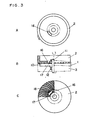
- FIG. 3 A, B, C As a means to present a tape guide allowing the tape to run smoothly, the cylinder constituted as represented .in FIG. 3 A, B, C was proposed in the Japanese unexamined patent publication Sho. 52-24507. That is, in FIG. 3 A, B, C, numeral 16 is an air guide hole, 17 is an air chamber formed annularly on the lower face of upper rotary cylinder 2, and 18 is multiple grooves with the either ends communicating with the air chamber 17 and the other ends reaching the outer circumference of the upper rotary cylinder 2.
- the present invention relates to a rotary head assembly in which a magnetic tape runs while being wound helically, consisting of a fixed cylinder having a fixed cylindrical part and a rotatable rotary member having a diameter approximately equal to that of said fixed cylinder, being mounted coaxially at a very small spacing, and having a magnetic head, wherein pump-out spiral grooves are provided in part or whole of the circumference on either plane of the opposing planes formed in the relative rotating parts between said fixed cylinder and said rotary member in order to radically eliminate the tape chirping phenomenon, sticking phenomenon, and tape damage and cylinder wear due to sliding by creating a buoyance by air pressure on a running magnetic tape not only in the rotary cylinder area but also in the fixed cylinder-area and realizing a stable and smooth tape running.
- FIG. 1 is a perspective diagram of a conventional rotary head assembly
- FIG. 2 is a sectional view of the same
- FIG. 3A is a plan view of other conventional rotary head assembly
- FIG. 3B is a front view of a partial section of the same
- FIG. 3C is a partially cutaway bottom view of the same
- FIG. 4 is a sectional view of a rotary head assembly in one of the embodiments of the present invention
- FIG. 5 is a bottom view of upper rotary cylinder of the same rotary head assembly
- FIG. 6 is a descriptive diagram of behavior of tape on a conventional rotary head assembly
- FIG. 7 is a descriptive diagram of behavior of tape on a rotary head assembly in one of the embodiments of the present invention
- FIG. 8 is a plan view of the same rotary head assembly
- FIG. 9 is a descriptive diagram of behavior of tape near the contact end of the tape to the cylinder in the same rotary head assembly
- FIGS. 10 and 11 are graphs of experimental data obtained by using the same rotary head assembly.
- FIG. 4 shows one of the embodiments of this invention, wherein pump-out type spiral grooves 20 are provided in the lower end plane of an upper rotary cylinder 19.
- numeral 21 is a lower fixed cylinder
- 22 is a disc
- 23 is a shaft
- 24 is a ball bearing
- 25 is a collar to fix the ball bearing by preloading.
- FIG. 5 illustrates the lower end of the upper rotary cylinder in the same embodiment, wherein the pattern of spiral grooves 20 is shown. In this diagram, the shaded area represents the grooves.
- the spiral grooves are provided on the ringshaped planes enclosed by concentric circles having radii r l , r 2 , wherein the shaded part 26 is the groove and 27 is the land.
- the air in the cylinder is .blown out to the outside.
- numeral 28 is a head base and 29 is a magnetic head.
- numeral 30 denotes the hole communicating the space inside the rotary head assembly with the outside, and 31 is a lead.
- the air discharged outside by the spiral groove 20 provides the magnetic tape with buoyancy, and forms a uniform air film over the entire sliding area of the magnetic tape on the outer circumference of the upper rotary cylinder and lower fixed cylinder 21, so that the sliding contact between the magnetic tape and rotary head assembly is avoided, thereby realizing a stable and smooth tape running.
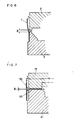
- FIGS. 6 and 7 demonstrate partial sectional views of the rotary head assembly of the conventional constitution and the present embodiment, respectively.
- the tape floats by a maximum of about 10 ⁇ in the upper rotary head assembly, while the tape is not lifted at all in the lower fixed head assembly but runs while keeping contact.
- the air pressure due to the air bearing effect by high speed rotation of the upper rotation cylinder leaks out, as indicated by the fine arrows in the diagram, partly from the upper end of the magnetic tape 1 and the rest through a small gap between upper and lower cylinders (usually 0.1 to 1 mm), so that the air pressure does not reach the lower fixed cylinder area.
- the air pressure due to rotation of said rotary cylinder does not leak out from the gap ( ⁇ 1 ) between the upper and lower cylinders, but, to the contrary, the air pressure to lift the magnetic tape 32 is heightened by the air stream discharged from the spiral grooves, and the air pressure reaches up to the lower fixed cylinder area, so that the tape is lifted from the lower fixed cylinder and runs without contact.
- the air pressure required for lifting the tape in an ordinary VTR is about 0.01 to 0.05 atg in average.
- the air discharge in this invention is due to the pressure created by the relative movements of the lower end of upper rotary cylinder 19 forming grooves 20 and the upper end of lower fixed cylinder 21 on its opposing plane, that is, due to the effect of pressure creation by shearing force derived from the viscosity of air.
- the gap ⁇ 1 must be approximately 100p or less.
- the length of the spiral groove in the radial direction (r 2 -r l ) should be .as long as possible.
- the optimum depth of the spiral grooves depends on the gap ⁇ 1 or the length of spiral groove in the radial direction (r 2- r 1 ), but the desired effect may not be obtained unless it is about 200p or less considering from the dimensions and specifications of the rotary head assembly of ordinary VTR, rotating speed of upper rotary cylinder, and other conditions.
- the shape and specifications of spiral grooves may be set by referring to known documents (for example "Design of Gas Bearings” by D. F. Wilcock, MTI, 1972).
- FIG. 8 is a top view of the rotary head assembly of the embodiment, wherein T 1 is the entry side back tension, T 2 is the exit side back tension, and arrow A shows the approximate position near the tape exit side obtained by measuring the lift of the magnetic tape 32 by optical sensor.
- FIG. 9 is a sectional view schematically representing the floating state of the magnetic tape 32 in the position indicated by arrow A in FIG. 8, and y in FIG. 9 denotes the lift of magnetic tape 32 at the position of w/3 from the lower end of magnetic tape 32 where w is the width of magnetic tape 32. In this experiment, the width w of magnetic tape 32 was 8 mm.
- FIG. 9 is a sectional view schematically representing the floating state of the magnetic tape 32 in the position indicated by arrow A in FIG. 8, and y in FIG. 9 denotes the lift of magnetic tape 32 at the position of w/3 from the lower end of magnetic tape 32 where w is the width of magnetic tape 32. In this experiment, the width w of magnetic tape 32 was 8 mm.
- FIG. 10 is a graph showing the result of measurement of tape lift y, wherein the axis of abscissas denotes the gap ⁇ 1 and the axis of ordinates represents the tape lift y, and the results of entry side back tension T 1 of 10 gf, 20 gf, 40 gf are shown.
- FIG. 11 is a graph showing the result of measurement of back tension of entry side and exit side, wherein the axis of abscissas denotes the entry side back tension T 1 and the axis of ordinates represnets the difference between exit side back tension T 2 and entry side back tension, and the results of measurement of gap ⁇ 1 of 30 ⁇ , 60 ⁇ , and 100 ⁇ are shown.
- FIG. 11 is a graph showing the result of measurement of back tension of entry side and exit side, wherein the axis of abscissas denotes the entry side back tension T 1 and the axis of ordinates represnets the difference between exit side back tension T
- the depth of spiral grooves of upper rotary cylinder used in this experiment was set at 120 ⁇ , and as a result of experiment with groove depth of 200p, the tape lifting effect was recognized up to the gap ⁇ 1 of 100 ⁇ .
- the method of fabrication of spiral grooves in this invention is a kind of press forming using molds having the convex and concave shapes of the groove and land of spiral grooves to be manufactured completely inverted. That is, so-called coining process is applicable. Burrs and local buildups caused by coining may be corrected by slightly dressing by means of lathe or drinder.
- the present invention is intended to present a rotary head assembly capable of recording and reproducing picture images of high quality at high reliability by creating the buoyancy of running magnetic tape by air pressure not only in the rotary cylinder area but also in the fixed cylinder area, realizing stable and smooth tape running, and radically eliminating the tape chirping phenomenon, and tape damage and wear accompanying sliding.
Landscapes
- Recording Or Reproducing By Magnetic Means (AREA)
Abstract
Applications Claiming Priority (4)
| Application Number | Priority Date | Filing Date | Title |
|---|---|---|---|
| JP57117168A JPS598160A (ja) | 1982-07-06 | 1982-07-06 | 回転ヘツドアセンブリ |
| JP117168/82 | 1982-07-06 | ||
| JP58068700A JPS59193570A (ja) | 1983-04-18 | 1983-04-18 | 回転ヘツドアセンブリ |
| JP68700/83 | 1983-04-18 |
Publications (3)
| Publication Number | Publication Date |
|---|---|
| EP0123694A1 true EP0123694A1 (fr) | 1984-11-07 |
| EP0123694A4 EP0123694A4 (fr) | 1987-01-29 |
| EP0123694B1 EP0123694B1 (fr) | 1990-09-26 |
Family
ID=26409901
Family Applications (1)
| Application Number | Title | Priority Date | Filing Date |
|---|---|---|---|
| EP83902128A Expired EP0123694B1 (fr) | 1982-07-06 | 1983-07-05 | Assemblage de tete rotative |
Country Status (5)
| Country | Link |
|---|---|
| US (1) | US4525757A (fr) |
| EP (1) | EP0123694B1 (fr) |
| AU (1) | AU570005B2 (fr) |
| DE (1) | DE3381911D1 (fr) |
| WO (1) | WO1984000438A1 (fr) |
Cited By (1)
| Publication number | Priority date | Publication date | Assignee | Title |
|---|---|---|---|---|
| EP0154120A1 (fr) * | 1984-01-23 | 1985-09-11 | Victor Company Of Japan, Limited | Dispositif pour le guidage de la bande dans un appareil d'enregistrement magnétique hélicoidal et de reproduction |
Families Citing this family (12)
| Publication number | Priority date | Publication date | Assignee | Title |
|---|---|---|---|---|
| JPS5936361A (ja) * | 1982-08-20 | 1984-02-28 | Matsushita Electric Ind Co Ltd | 回転ヘツドアセンブリ |
| JPS61107523A (ja) * | 1984-10-31 | 1986-05-26 | Hitachi Ltd | 回転ドラム装置 |
| JPH04265559A (ja) * | 1991-02-21 | 1992-09-21 | Sony Corp | 回転ドラムアセンブリ |
| JPH04276322A (ja) * | 1991-03-01 | 1992-10-01 | Sony Corp | 回転光学ヘッド装置 |
| US5359475A (en) * | 1992-03-23 | 1994-10-25 | Minnesota Mining And Manufacturing Company | Air filter system for helical scanner drum with vented drum cover |
| US5788425A (en) * | 1992-07-15 | 1998-08-04 | Imation Corp. | Flexible system for handling articles |
| US5432653A (en) * | 1993-06-22 | 1995-07-11 | Minnesota Mining And Manufacturing Company | Loop-shaped pneumatic drive |
| US5485325A (en) * | 1994-04-04 | 1996-01-16 | Minnesota Mining And Manufacturing Company | Magazine storage system for recording strips |
| US6336608B1 (en) * | 2000-02-29 | 2002-01-08 | James Robert Cope | Flexible web roller guide assembly with an integral centrifugal pump capability to provide a hydrostatic air bearing function to the roller guides outside supporting surface |
| US6443389B1 (en) * | 2000-10-19 | 2002-09-03 | Eastman Kodak Company | Self threading air bar |
| US6853515B1 (en) * | 2003-02-27 | 2005-02-08 | Tandberg Storage Asa | Tape drive with fan on take-up hub |
| JP4143520B2 (ja) * | 2003-11-11 | 2008-09-03 | 富士フイルム株式会社 | 無接触搬送装置 |
Family Cites Families (16)
| Publication number | Priority date | Publication date | Assignee | Title |
|---|---|---|---|---|
| NL277005A (fr) * | 1962-04-09 | |||
| JPS5099705A (fr) * | 1973-12-29 | 1975-08-07 | ||
| US3939493A (en) * | 1974-09-30 | 1976-02-17 | International Business Machines Corporation | Tape lifter |
| DE2535780C3 (de) * | 1975-08-11 | 1978-10-05 | Igor Alekseewitsch Moskau Kryltsov | Magnetbandlaufwerk für Videobandgeräte mit Längsspuraufzeichnung |
| US4012792A (en) * | 1975-08-11 | 1977-03-15 | Eastman Kodak Company | Magnetic head drum configuration having a friction reducing helical step |
| JPS6019061B2 (ja) * | 1975-08-19 | 1985-05-14 | 松下電器産業株式会社 | テ−プガイド |
| JPS5942386B2 (ja) * | 1975-08-19 | 1984-10-15 | 松下電器産業株式会社 | テ−プガイド |
| JPS5223929Y1 (fr) * | 1975-10-08 | 1977-05-31 | ||
| JPS5951065B2 (ja) * | 1977-02-05 | 1984-12-12 | ソニー株式会社 | 回転ヘツド装置 |
| JPS5469637A (en) * | 1977-11-11 | 1979-06-04 | Matsushita Electric Ind Co Ltd | Rotation transmitting equipment |
| JPS5951066B2 (ja) * | 1978-04-17 | 1984-12-12 | ソニー株式会社 | 記録再生装置 |
| US4266255A (en) * | 1978-04-26 | 1981-05-05 | Iit Research Institute | Capstan drive system for driving tape record media, and having internally mounted transducer head means |
| NL7906478A (nl) * | 1979-08-29 | 1981-03-03 | Philips Nv | Inrichting ten behoeve van het magnetisch inschrijven en uitlezen van signalen van grote bandbreedte. |
| JPS56137549A (en) * | 1980-03-27 | 1981-10-27 | Matsushita Electric Ind Co Ltd | Rotating head cylinder device |
| JPS5951067B2 (ja) * | 1980-08-14 | 1984-12-12 | 松下電器産業株式会社 | 磁気記録再生装置のヘッドドラム装置 |
| JPS5832265A (ja) * | 1981-08-20 | 1983-02-25 | Matsushita Electric Ind Co Ltd | 磁気記録再生装置 |
-
1983
- 1983-07-05 AU AU17076/83A patent/AU570005B2/en not_active Ceased
- 1983-07-05 WO PCT/JP1983/000214 patent/WO1984000438A1/fr not_active Ceased
- 1983-07-05 US US06/598,548 patent/US4525757A/en not_active Expired - Fee Related
- 1983-07-05 DE DE8383902128T patent/DE3381911D1/de not_active Expired - Lifetime
- 1983-07-05 EP EP83902128A patent/EP0123694B1/fr not_active Expired
Cited By (1)
| Publication number | Priority date | Publication date | Assignee | Title |
|---|---|---|---|---|
| EP0154120A1 (fr) * | 1984-01-23 | 1985-09-11 | Victor Company Of Japan, Limited | Dispositif pour le guidage de la bande dans un appareil d'enregistrement magnétique hélicoidal et de reproduction |
Also Published As
| Publication number | Publication date |
|---|---|
| EP0123694B1 (fr) | 1990-09-26 |
| EP0123694A4 (fr) | 1987-01-29 |
| US4525757A (en) | 1985-06-25 |
| AU570005B2 (en) | 1988-03-03 |
| WO1984000438A1 (fr) | 1984-02-02 |
| DE3381911D1 (de) | 1990-10-31 |
| AU1707683A (en) | 1984-02-08 |
Similar Documents
| Publication | Publication Date | Title |
|---|---|---|
| EP0123694A1 (fr) | Assemblage de tete rotative | |
| US4414592A (en) | Support for stabilizing the movement of a magnetic medium over a magnetic head | |
| JPH0243263B2 (fr) | ||
| US3961369A (en) | Rotating head apparatus having a protruding diameter headwheel which supports a protruding flying head | |
| US6745976B1 (en) | Data tape speed tachometer using a porous roller bearing | |
| KR900001620Y1 (ko) | 가이드 드럼 | |
| JPH08235544A (ja) | ビデオカセットレコーダ用ヘッドドラムアセンブリ | |
| KR100603080B1 (ko) | 회전형헤드드럼조립체 | |
| EP0333431A2 (fr) | Appareil stabilisateur pour transducteur et support d'enregistrement | |
| US3996615A (en) | Rotary air bearing head with leading edge controlling air bearing | |
| US5833125A (en) | Pinch roller assembly for use in a video cassette recorder | |
| JPH0449164B2 (fr) | ||
| JPH0456378B2 (fr) | ||
| US5774307A (en) | Head drum assembly designed to prevent a magnetic tape from adhering to a drum surface | |
| JPS59193570A (ja) | 回転ヘツドアセンブリ | |
| JPS59110064A (ja) | 回転ヘツドアセンブリ | |
| JP2789224B2 (ja) | 情報記録再生用ドラム装置 | |
| JPH076456A (ja) | 磁気記録再生用回転ドラムアセンブリ | |
| JPS598160A (ja) | 回転ヘツドアセンブリ | |
| KR200142934Y1 (ko) | 핀치 롤러 조립체 | |
| JP3270797B2 (ja) | 負圧スライダ | |
| JPH0642311B2 (ja) | フレキシブルディスクカートリッジ | |
| JPS6146897B2 (fr) | ||
| JPS5938961A (ja) | 回転ヘツドアセンブリ | |
| JPS6066357A (ja) | 回転ヘッドアセンブリ |
Legal Events
| Date | Code | Title | Description |
|---|---|---|---|
| PUAI | Public reference made under article 153(3) epc to a published international application that has entered the european phase |
Free format text: ORIGINAL CODE: 0009012 |
|
| 17P | Request for examination filed |
Effective date: 19840309 |
|
| AK | Designated contracting states |
Designated state(s): DE FR GB |
|
| A4 | Supplementary search report drawn up and despatched |
Effective date: 19870129 |
|
| 17Q | First examination report despatched |
Effective date: 19880616 |
|
| GRAA | (expected) grant |
Free format text: ORIGINAL CODE: 0009210 |
|
| AK | Designated contracting states |
Kind code of ref document: B1 Designated state(s): DE FR GB |
|
| REF | Corresponds to: |
Ref document number: 3381911 Country of ref document: DE Date of ref document: 19901031 |
|
| ET | Fr: translation filed | ||
| PLBE | No opposition filed within time limit |
Free format text: ORIGINAL CODE: 0009261 |
|
| STAA | Information on the status of an ep patent application or granted ep patent |
Free format text: STATUS: NO OPPOSITION FILED WITHIN TIME LIMIT |
|
| 26N | No opposition filed | ||
| PGFP | Annual fee paid to national office [announced via postgrant information from national office to epo] |
Ref country code: GB Payment date: 19930625 Year of fee payment: 11 |
|
| PGFP | Annual fee paid to national office [announced via postgrant information from national office to epo] |
Ref country code: FR Payment date: 19930709 Year of fee payment: 11 |
|
| PGFP | Annual fee paid to national office [announced via postgrant information from national office to epo] |
Ref country code: DE Payment date: 19930719 Year of fee payment: 11 |
|
| PG25 | Lapsed in a contracting state [announced via postgrant information from national office to epo] |
Ref country code: GB Effective date: 19940705 |
|
| GBPC | Gb: european patent ceased through non-payment of renewal fee |
Effective date: 19940705 |
|
| PG25 | Lapsed in a contracting state [announced via postgrant information from national office to epo] |
Ref country code: FR Effective date: 19950331 |
|
| PG25 | Lapsed in a contracting state [announced via postgrant information from national office to epo] |
Ref country code: DE Effective date: 19950401 |
|
| REG | Reference to a national code |
Ref country code: FR Ref legal event code: ST |