EP0333431A2 - Appareil stabilisateur pour transducteur et support d'enregistrement - Google Patents
Appareil stabilisateur pour transducteur et support d'enregistrement Download PDFInfo
- Publication number
- EP0333431A2 EP0333431A2 EP89302500A EP89302500A EP0333431A2 EP 0333431 A2 EP0333431 A2 EP 0333431A2 EP 89302500 A EP89302500 A EP 89302500A EP 89302500 A EP89302500 A EP 89302500A EP 0333431 A2 EP0333431 A2 EP 0333431A2
- Authority
- EP
- European Patent Office
- Prior art keywords
- recording medium
- block member
- stabilising device
- storage disk
- flexible storage
- Prior art date
- Legal status (The legal status is an assumption and is not a legal conclusion. Google has not performed a legal analysis and makes no representation as to the accuracy of the status listed.)
- Granted
Links
- 230000000087 stabilizing effect Effects 0.000 title description 113
- 230000003019 stabilising effect Effects 0.000 claims abstract description 78
- 230000003068 static effect Effects 0.000 claims abstract description 12
- 238000011144 upstream manufacturing Methods 0.000 claims description 28
- 230000015572 biosynthetic process Effects 0.000 claims description 4
- 238000009826 distribution Methods 0.000 description 36
- 238000004088 simulation Methods 0.000 description 6
- 230000000694 effects Effects 0.000 description 5
- 230000001105 regulatory effect Effects 0.000 description 4
- 238000006073 displacement reaction Methods 0.000 description 3
- 239000000463 material Substances 0.000 description 3
- 238000000034 method Methods 0.000 description 3
- 239000011248 coating agent Substances 0.000 description 2
- 238000000576 coating method Methods 0.000 description 2
- 230000007423 decrease Effects 0.000 description 2
- 238000004519 manufacturing process Methods 0.000 description 2
- 238000010926 purge Methods 0.000 description 2
- 230000002159 abnormal effect Effects 0.000 description 1
- 238000005094 computer simulation Methods 0.000 description 1
- 239000012530 fluid Substances 0.000 description 1
- 239000007787 solid Substances 0.000 description 1
- 230000006641 stabilisation Effects 0.000 description 1
- 238000011105 stabilization Methods 0.000 description 1
Images


Classifications
-
- G—PHYSICS
- G11—INFORMATION STORAGE
- G11B—INFORMATION STORAGE BASED ON RELATIVE MOVEMENT BETWEEN RECORD CARRIER AND TRANSDUCER
- G11B17/00—Guiding record carriers not specifically of filamentary or web form, or of supports therefor
- G11B17/32—Maintaining desired spacing between record carrier and head, e.g. by fluid-dynamic spacing
Definitions
- the present invention relates to a transducer/ recording medium stabilizing device and in particular to a transducer/recording medium stabilizing device for contacting a recording/reproducing head which is used as a transducer with a magnetic recording medium in a stable and intimate manner.
- a magnetic recording/reproducing device for recording and/or reproducing video information and the like using a recording medium comprising a flexible magnetic disk which is in the form of a circular sheet
- the recording medium is rotated at a high speed with respect to a magnetic head to obtain high quality recorded and reproduced video signals.
- the magnetic head is brought into sliding contact with a magnetic surface of the recording medium which is rotating at a high speed (for example, 3600 rpm) to accomplish high quality video recording and reproducing.
- Techniques to obtain a stable head contact with a recording medium by slidably contacting the recording medium with the head at a constant pressure includes two types of techniques, namely a positive pressure system and a negative pressure system.
- the former system involves disposing a hard pad at an opposite side of a recording medium with respect to the magnetic head, so that a positive pressure is formed by an air stream formed between the pad and a sheet to bring the head into pressure contact with the sheet.
- the latter system involves disposing a contact stabilizing device (referred to as sucking ring) having a magnetic head embedded at the centre thereof and an annular recess surrounding the head so that the device is movable in a radial direction in an opposing manner with respect to the magnetic surface of the recording medium, forming a negative pressure by an airstream formed when the recording medium is rotated at a high speed and forming a sucking pressure to suck the recording medium toward the head by the negative pressure.
- sucking ring a contact stabilizing device having a magnetic head embedded at the centre thereof and an annular recess surrounding the head so that the device is movable in a radial direction in an opposing manner with respect to the magnetic surface of the recording medium
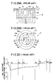
- Fig. 28 of the accompanying drawings shows an example of a conventional recording medium regulating device for recording and reproducing video information on and from the recording medium by slidably contacting the flexible magnetic recording medium with the head in accordance with the above-described negative pressure system.
- the recording medium 1 having a magnetic coating on the underside thereof, which is formed into a circular sheet is provided with a chucking centre hub 4 at the centre thereof.
- the centre hub 4 is chucked to a spindle shaft 6a of a spindle motor 6a.
- the thus chucked recording medium 1 is rotated clockwise at a high speed by means of a motor 6.
- a carriage 5 is disposed in a parallel relationship with the recording medium therebelow.
- a contact stabilizing device 3 is disposed on the upper side of the carriage 5 in the vicinity of one side thereof (the left-hand side as viewed in the drawing).
- a magnetic head disposed at the centre of the slide contact device 3 is adapted to make contact with the lower magnetic coating of the recording medium 1.
- the carriage 5 is adapted to move in a radial direction (a direction shown by an arrow a in the drawing) by an access motor 7 secured to a chassis board (not shown) disposed below the carriage 5. That is, a lead screw (not shown) is mounted on a rotary shaft of the access motor 7. The lead screw is screwed into a screw hole (not shown) for moving the carriage 5. Accordingly when the motor 7 is driven, the carriage 5 is moved by the lead screw in a direction shown by the arrow a along a guide shaft 8 disposed at one side (front side as viewed in the drawing) of the carriage 5 to cause the magnetic head to slide in the radial direction of the recording medium for accessing the head 2 to a desired track.
- a stabilising guide plate 9 which makes it easy to slidably contact the recording medium with the magnetic head 2 of the contact stabilising device at the start of rotation of the recording medium 1 is mounted on a stud (not shown) secured to the chassis board.
- the stabilising guide plate 9 slides on the upper surface of the recording medium 1 upstream with respect to the stabilising device 3.
- the centre hub 4 of the recording medium 1 is chucked to the spindle shaft 6a of the spindle motor 6 and the spindle motor 6 is rotated.
- the recording medium 1 is thus rotated at a high speed.
- a negative pressure is formed between the recording medium 1 and the contact stabilising device 3 so that the megative pressure causes the recording medium 1 to be sucked to the contact stabilising device 3 so that the magnetic head 2 embedded in the device 3 slides on the recording medium 1.
- a conventional contact stabilising device used as a recording medium regulating device generally forms spaces around a magnetic head and is disposed in an opposing relationship with a recording medium together with the head as is disclosed in, for example, Japanese Laid-Open Patent Application Sho 59-54071.
- the recording medium moves, the air in these spaces is entrained by the moving recording medium to flow away from the spaces. Since less amount of air flows into the spaces than the amount of air which flows away from the spaces, a negative pressure is formed in the spaces.
- the moving recording medium is sucked to the contact stabilizing device so that it slides on the magnetic head in an intimate contact relationship therewith.
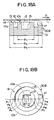
- a magnetic head contact stabilisng device 3 shown in Figs. 29A and 29B comprises a base block member 10, a first block member 10a at the centre thereof having a head embedded hole 15 in which a magnetic head 2 is embedded, said first block member 10a being arranged to project from the upper surface of the base block member 10 toward the recording medium 1, the upper surface of the base block member 10a providing a first recording medium sliding contact surface 12, an annular groove 13 formed around the first block member 10a, and a second annular block member 10b around the groove 13 which projects from the base block member 10 toward the recording medium, the upper surface of the second block member 10b providing a second recording medium sliding contact surface 14.
- the dimensions of various portions are as follows.
- the inner and outer diameter of the groove 13 ⁇ 1 and ⁇ 2 are 3.5mm and 6mm respectively.
- the inner diameter of the recording medium sliding contact surface 14 of the second block member ⁇ 3 is 7mm and the depth of the groove 13 is 50 ⁇ m.
- the spacing between the recording medium sliding contact surface 14 of the contact stabilizing device 3 and the recording medium 1 is maintained at 1 ⁇ m.
- the air pressure is less than the atmospheric pressure at a region (points P1 to P6) upstream in the moving direction of the medium sliding contact surface 12 of the first block member 10a of the contact stabilising device 3, while the pressure is positive at a region (points P6 to P8) of the groove 13 and the recording medium sliding contact surface 14 of the second block member 10b downstream in the moving direction.
- the suction pressure between the contact stabilising device 3 and the recording medium 1 is unstable at the downstream region and the movement of the medium becomes unstable. It is apparent from the actually measured data that the recording medium 1 vibrates to cause the medium to flutter so that it is unable to provide a stable movement to the medium. It is considered that the formation of a positive pressure is due to the fact that the air stream stays downstream of the groove 13, so that this increases the pressure at a downstream region.
- a magnetic head 2 is embedded in the hole 15 at the centre of the sliding contact surface 12 of the first block member 10a.
- the magnetic head 2 projects slightly from the surface 12.
- the length of projection of the magnetic head 2 is not particularly considered in this simulation. This is adapted to the following embodiments and other contact stabilising devices.
- the amplitude of the negative pressure formed in the contact stabilising device depends on the relative speed of the recording medium 1 with respect to the magnetic head 2, the profiles of the negative pressure distribution would be substantially the same, independently of the relative speed, if the dimensions of various parts of the contact stabilising device 3 are determined.
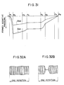
- Fig. 31 is a graph in which the established negative pressure is plotted with respect to the relative moving speed of the medium.
- Solid and dotted lines l100 and l200 represent the pressure distribution when the relative speed is 7.5m/s and 3.75m/s respectively. It is apparent from the comparison of the solid line l100 with the dotted line l200 that the established negative pressure is proportional to the relative speed.
- the negative pressure formed between the recording medium 1 and the contact stabilising device 3 is proportional to the relative speed of the recording medium 1 with respect to the magnetic head 2, that is, the rotational speed of the recording medium 1 in the rotational speed of the recording medium 1 decreases the established pressure, resulting in an unstable head contact.
- the rotational speed of the recording medium 1 on normal recording and/or reproducing is, for example, 3600 rpm
- the rotational speed of the recording medium is reduced to half speed as high as 1800 rpm in order to erase the video information recorded on the recording medium 1.
- the standards on still video floppy (SVF) specify that one field of video information is recorded on one track, one frame of video information may sometimes have to be recorded on one track.
- the rotational speed of the recording medium 1 should be reduced to half. Reduction of the rotational speed to half in such a manner reduces the established negative pressure by half, resulting in an unstable head contact.
- Figs. 32A and 32B are waveform views showing envelops of signals (generally referred to as RF signal) which are recorded on and reproduced from the recording medium 1 during one rotation of the recording medium.
- Fig 32A shows a flat envelop which is obtained when the head contact is normal while
- Fig. 32B shows an envelop in which the reproduced signal has an abormally lowered level when the head contact is unstable.
- the signal having an abnormally lowered level is generated when the head contact is not good during recording of video information or when the head contact is unstable during reproducing of video information. It is also generated when the head contact is not good during both recording and reproducing. Since such a large drop-out signal can not be produced in any event, the video information corresponding to this drop-out will be lost.
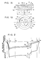
- a stable contact of the recording medium with the transducer can be obtained in spite of changes in rotational speed of the recording medium by slightly inclining the opposing surface of the contact stabilising device with respect to the motion direction of the recording medium.
- a magnetic head is used as a transducer.
- the contact stabilising device 3A of Figs. 1A and 1B differs from the conventional stabilising device 3 in that a notch 17 is formed on the sliding contact surface 14 of the second block member 10b external to the groove 13.
- the notch 17 is therefore in the region of the device downstream with respect to the direction of motion of the recording medium 1. Repetition of the description of the portions of the device 3A which are substantially similar in shape and dimensions to the conventional device shown in Figs. 29A and 29B is omitted hereinbelow.
- Fig. 2 Study of fluidic dynamical simulation shows that distribution of air between the contact stabilising device 3A and the recording medium 1 to be as shown in Fig. 2.
- characteristic curves l1, l2 and l3 are obtained when the depth of the notch 17 is 10 ⁇ m, 30 ⁇ m and 50 ⁇ m, respectively.
- the air pressure between the recording medium 1 and the entire surface of the stabilising device opposing to the recording medium 1 is negative when the notch 17 is provided.
- the characteristic lines l1 to l3 the level of negative pressure is changed while the profile of the pressure distribution remains substantially similar even when the depth of the notch 17 is changed.
- the profile of the pressure distribution comprises a line which abruptly falls from 0 level (atmospheric pressure) to a negative pressure between points P1 and P2, a line which is maintained at a substantially constant negative pressure level between points P2 to P6, and a positive inclined line to 0 level between points P6 to P8.
- a further notch 16 may be formed on the protruding surface 12 of the first block member 10a at a region of the device downstream with respect to the motion of the recording medium as shown by two dot chain lines in Figs. 1A and 1B in addition to notch 17. If the notch 16 is provided, the pressure distribution in the vicinity of the notch 16 is represented by characteristic lines l1′, l2′ and l3′ when the depth of the notch 16 is 10 ⁇ m, 30 ⁇ m and 50 ⁇ m (i.e. the same as that of the notch 17), respectively.
- the air pressure which has been positive between points P6 and P8 in the conventional contact stabilising device 3 is always made negative over an entire range between points P1 and P8, including the range between points P6 and P8, by merely forming the notch 17. It is considered that this is due to the effect that increase in pressure downstream is prevented since the air stream in the groove 13 downstream is released or purged to outside of the contact stabilising device 3A through the notch 17.
- the inner notch 16 need not be provided so far as can be seen from the characteristic lines in Fig. 2. Since it is necessary to form a recess in which the magnetic head 2 is mounted below the protruding surface 12, it is desirable to form the recess in such a manner that it is continuous with the notches 17 and 16 (refer to Figs. 3 and 4) in term of fabrication procedure.
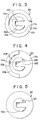
- the contact stabilising devices 3B of the second embodiment shown in Fig. 3 is provided with a notch 16A which is formed by extending the notch 16 in device 3A in the upstream direction. That is, the notch 16A extends in a radial direction from an upstream point to a downstream point on the protruding surface 12A, or medium contact sliding surface of the first block member 10a of the stabilising device 3B coincides with the position of a notch 17A corresponding to the notch 17, formed on the medium contact sliding surface 14A of the second block 10B member beyond the groove 13A.
- the pressure distribution of the air between the stabilising device 3B and the recording medium 1 is represented by a characteristic line l4 in Fig. 6. If the notches 17A and 16A and the groove 13A are 20 ⁇ m in depth, the air pressure distribution is represented by a characteristic line l4.
- the contact stabilising device 3c of a third embodiment shown in Fig. 4 includes a notch 17B which is formed by enlarging the notch 17A in the device 3B. That is, a medium sliding contact surface 14B of a second block member 10b outside of a groove 13B is formed in a semi-annular form only upstream so that a notch 17B is formed by removing the second block member 10b downstream.
- the notch 17B is coplanar with the groove 13B.
- the notch 16B on the medium sliding contact surface 12B is identical with the notch 16A.
- a pressure distribution between the stabilising device 3C and the recording medium 1 is represented by a characteristic line l6.
- a contact stabilising device 3D hving a profile as shown in Fig. 5 is formed by removing the medium sliding contact surface 14B of the protruding second block member 10B in the stabilising devcie 3C
- the pressure distribution between the recording medium 1 and the stabilising device 3D is represented by characteristic lines l7 and l8 in Fig. 6. This shows that a positive pressure is formed upstream.
- the characteristic lines l7 and l8 are obtained when the height of the medium sliding contact surface 12c of the first block member 10a (that is, the depth of the portion other than the first block 10a) is 20 ⁇ m and 50 ⁇ m, respectively.
- the second block 10b With a notch downstream to reduce the positive pressure to form a negative pressure. If the medium sliding contact surface at the upstream side is entirely removed, the pressure would be increased to form a static pressure upstream. Accordingly, it is impossible to remove in its entirety the upstream part of the medium sliding contact surface.
- Stabilising devices 23 and 23A having a notch of various shapes formed therein, without forming any notch on the medium sliding contact surface of the second block member 10B are shown in Figs. 7 and 8 for reference.
- the contact stabilising device 23 shown in Fig. 7 corresponds to a stabilising device 3B having no notch 17A shown in Fig. 3.
- the pressure distribution between the recording medium 1 and the stabilising device 23 is represented by a characteristic line l9.
- the pressure distribution is represented by the characteristic lines l10 and l11 respectively.
- the stabilising device 23A shown in Fig. 8 is similar to the stabilising device 23 excepting that the notch 25A is enlarged downstream when the depth of the groove 22A inside the medium sliding contact surface 24A of the second block member 10b is 50 ⁇ m and the depth of the enlarged notch 25A in the medium sliding contact surface 21A of the first block member 10a is 20 ⁇ m.
- the pressure distribution between the recording medium 1 and the device 23A is represented by a characteristic line l12 in Fig. 9.
- the pressure distribution is represented by a characteristic line l13.
- each of characteristic lines l9 to l13 shows that the pressure at the downstream side (points P6 to P8) is positive. Accordingly, it is appreciated that there is no effect to decrease the static pressure at the downstream side for forming a negative static pressure unless a notch is provided downstream of the medium sliding contact surfaces 24, 24A of the second block member 10b as in the contact stabilising devices 23, 23A, even if a notch having any shape is formed on the medium sliding contact surfaces 21, 21A of the first block member 10a.
- the contact stabilising device of the present invention is not limited to the profiles in the above-mentioned embodiments shown in Figs. 1A, 1B, 3 and 4, but may have various other profiles.
- the central medium sliding contact surface of the first block member 10a at the centre, the groove and the medium sliding contact surface of the second block outside of the groove are formed in a concentric manner in the above embodiments. They need not always be circular or annular, but may be formed into other profiles including an ellipse or a rectilinear part.
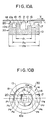
- a contact stabilising device of a fourth embodiment of the present invention will be described with reference to Figs. 10a and 10B.
- the stabilising device 30 is substantially identical to the contact stabilising device 3A in profile and dimensions, but is different from the device 3A in that nothces 20 and 17 having a width substantially the same as that of a head adapted hole 15 are formed on the medium sliding contact surface 14 upstream and downstream portions of the second block member 10B respectively.
- notches 19 and 18 having a width the same as that of the head hole 15 are formed on the medium sliding contact surface 12 of the first block member 10a upstream and downstream sides as viewed from the hole 15 in which a magnetic head is mounted.
- a groove 13 is formed between the first and second block members 10a and 10B respectively as viewed from the hole 15. Upstream notches 20 and 19 are relatively shallow in depth while downstream notches 18 and 17 are relatively deep. The notches 19 and 20 make it easy to introduce air into the groove 13 and the notches 18, 17.
- third dynamic simulation shows the pressure distribution shown in Fig. 11 when the atomospheric pressure between the stabilizing device 30 and the recording medium 1 is 0 level.
- a characteristic line l21 is obtained when the depth of the notches 19, 20 and 17, 18 is 10 ⁇ and 20 ⁇ m, respectively.
- a characteristic line l22 is obtained when the depth of the notches 19, 20 and 17, 18 is 10 ⁇ m and 30 ⁇ m, respectively.
- a characteristic line l23 is obtained when the depth of the notches 19, 20 and 17, 18 is 10 ⁇ m and 50 ⁇ m, respectively.
- the air pressure between the recording medium and the entire surface of the stabilizing device 30 opposing the recording medium is negative when there are the notches 19, 20 and 17, 18. Even if the depth of the downstream notches 17, 18 is changed, the level at points P3 - P6 is slightly changed in an uniform manner.
- a negative pressure is also formed over the entire surface of ihe stabilizing device 30 opposing the recording medium 1.
- the profile of the pressure distribution includes a line which falls abruptly from 0 level (atomospheric pressure) to a negative pressure between points P1 and P2, a line maintained at a substantially constant negative level between points P2 and P6, and a line which increase to 0 level between points P6 and P8.
- the relative pressure over the entire region between points P1 and P8, including a region between points P6 and P8, is made negative by forming notches 17 to 20 similarly to the stabilizing device 30 while the relative pressures at the region between points P6 and P8 was positive in the conventional stabilizing device. It is considered that this is due to the effect that the increase in pressure in this downstream region is prevented since the air stream downstream of the groove 13 is purged to the outside of the stabilizing device 30 through the notch 17, similarly to the first embodiment.
- Fig.19 shown the result of simulation of the stabilizing devices 30A and 30B shown in Figs. 17A, 17B and 18A, 18B, respectively, which are constructed similarly to the first embodiment shown in Figs. 1A and 1B for comparison.
- the stabilizing device 30A is different from the stabilizing device 30 of the above-mentioned embodiment in that it is not provided with upstream notches 19 and 20.
- the stabilizing device 30B is different from the stabilizing device 30 in that it is not provided with upstream notches 19 and 20 and a downstream notch 18b on the second block member 10B. That is, the stabilizing device 30A is provided with a notch 18 on the first block member 10a and a notch 17 on the second block member 10b, downstream.
- the stabilizing device 30B is provided with only a notch 17 on the second block member 10b, downstream.
- Characteristic lines l24 and l25 in Fig. 19 show the pressure distribution in the stabilizing devices 30A and 30B respectively.
- the depth of both the notches 18 and 17 of the stabilizing device 30A and the depth of the notch 17 of the stabilizing device 30B is 50 ⁇ m.
- the pressure is negative over the entire region between points p1 and P8 although the profile of the pressure distribution of these stabilizing devices 30A and 30B is slightly different from that of the stabilizing device 30.
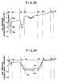
- Figs. 23 and 24 show the result of study of a case in which each of the stabilizing devices 30A, 30B is disposed with respect to the medium in such a manner that the medium sliding contact surface is inclined to the horizontally disposed recording and/or playback surface of the medium at an angle ⁇ at the downstream side with respect to the motion direction of the medium 1, as is shown in Fig. 22.
- Figs. 23 and 24 providing a large inclination angle ⁇ of the medium sliding contact surface of the stabilizing device 30A, 30B makes the spacing between the medium and the sliding contact surface exessively large and cancel the variation in pressure due to atomospheric pressure while the negative pressure largely changes when the inclination angle ⁇ is very small.
- Characteristic lines l26, l27 and l28 in Fig. 23 are obtained when the inclination angle ⁇ of the stabilization device 30A is 0.005°, 0.01° and 0.02° respectively.
- Characteristic lines l29, l30 and l31 of Fig. 24 are obtained when the inclination angle ⁇ of the stabilizing device is 0.005°, 0.01° and 0.02° respectively.
- the stabilizing device 30A and 30B When an experiment to record and reproduce using the stabilizing devices 30A and 30B is conducted, the stabilizing device sometimes sticks abnormally to the recording medium 1, resulting in abnormal motion of the recording medium 1. It is considered that the results of afore-mentioned simulation support the facts of this experiment,
- Characteristic lines l32, l33 and l34 shown in Fig. 12 are obtained when the stabilizing device 30 is slightly inclined to the recording medium at an angle ⁇ , 0.005°, 0.01° and 0.02° respectively similarly to the stabilizing devices 30A and 30B shown in Fig. 22. Comparison of these characteristic lines l32,l33 and l34 with the characteristic line l21 obtained when the stabilizing device 30 is not inclined shows that little variation of negative pressure is found even when the stabilizing device 30 is inclined. Of course, a negative pressure is formed over the entire region between points P1 and P8. Accordingly it is considered that elevation of relative pressure can be prevented since the notches 20 and 19 effectively function as an air stream purge way by provision of upstream notches 16 and 17 even when the stabilizing device 30 is inclined.
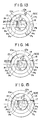
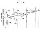
- the stabilizing device 30C of the fifth embodiment in Fig. 13 is formed with a notch 17C which is an enlarged downstream notch 17 of the second block member 10B in the stabilizing device 30.
- a characteristic line l35 in Fig. 16 which is obtained when the depth of upstream notches 19 and 20 is 10 ⁇ m and the depth of downstream notches 18, 17C is 30 ⁇ m.
- the stabilizing device 30D of the sixth embodiment shown in Fig. 14 and the stabilizing device 30E of the seventh embodiment shown in Fig. 16 are provided with any one of upstream notches 19 and 20 in the stabilizing device 30.
- the stabilizing device 30D has only the notch 20 upstream.
- the stabilizing device 30E has only the notch 19.
- the pressure distribution in the stabilizing devices 30D and 30E are shown by characteristic lines l36 and l37 in Fig. 16, respectively. As is apparent from these characteristic lines l35 to l37, a negative pressure is formed over an entire region between points P1 and P8 and the profile of the pressure distribution is relatively flat in all stabilizing devices 30C, 30D and 30E.
- a negative pressure is obtained over the entire region and the profile of the negative pressure distribution does not change significantly even when the stabilizing device is inclined with respect to the recording medium 1 due to the fact that the stabilizing device has a notch on at least the second block member 10B downstream with respect to the head 2 and has a notch on the first and/or second block member upstream.
- the stabilizing device of the present invention is not limited to the profile shown in Figs. 10A, 10B and 13 to 15.
- the width and depth of the notches 17 to 20 may be changed.
- the recording medium sliding contact surface of the first block member need not be concentric with the groove, and the medium sliding contact surface of the second block.
- the stabilizing device may have a profile in the form of an ellipse or a rectilinear portion.
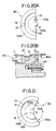
- a contact stabilizing device 40 of an eighth embodiment is shown in Figs. 20A and 20B.
- the stabilizing device 40 comprises a small column like base block member 10a having a semicircular cross-section, semicircular first and second block members 10Aa and 10Ab on the base block 10a which are integral therewith, and a magnetic head 2 at the center of a terminating face 40a for saving material and ease of fabrication and maintainance while the afore-mentioned stabilizing device comprises first and second block members 10a and 10b which are concentrically disposed on a small column like base block member 10 and protrudes therefrom so that coacting of the block members with a groove 13 forms a negative pressure for sucking a medium.
- the stabilizing device 40 comprises only an upstream half of the stabilizing device 3A of the first embodiment of the present invention shown in Fig. 1A and 1B.
- the stabilizing device 40 of the eighth embodiment is equivalent to the stabilizing device 3C of the third embodiment of the present invention shown in Fig. 4 in which a downstream half of the device is omitted.
- a sufficient negative pressure for sucking a medium can be formed and a positive pressure which is formed at the rear half of the device can be eliminated if the device is formed in such a manner.
- the device can be made of only half the amount of material and is easily fabricated since the rear half of the device is open. Maintainance of the stabilizing device is easy since it is easy to mount or remove the magnetic head 2.
- the rear half positive pressure eliminating means may be formed as a sector notch 50a at the downstream rear half as in the stabilizing device 50 of the ninth embodiment of the present invention shown in Fig. 21. That is, the stabilizing device 50 comprises a first and second block members 10Ba and 10Bb which are concentrically formed on the upper surface of a base block member 10B having a notch 50a which is formed by removing a sector like downstream portion. A magnetic head 2 is removably disposed at the center of a terminating face 50b which is removed in a sector form.
- the same operation and effect as that of the stabilizing device 4D of the eighth embodiment can be obtained if the stabilizing device is formed in such a manner.
- the angle ⁇ of the sector which is removed is optional.
- the contact stabilizing device of the tenth embodiment of the present invention assures a stable contact with a recording medium in order to accomplish other purposes of the present invention even when the rotational speed of the recording medium is different between recording/reproducing and erasing.
- a stabilizing device 60 of the tenth embodiment comprises a magnetic head 2, the center thereof which serves as a transducer and a suction ring in which a notch 60a is provided in a downstream portion.
- the stabilizing device 60 is supported in a cantilever manner at the upstream lower end 10C thereof by a spherical bearing 61 on the device supporting member 62 secured on a head carriage 5 (refer to Fig. 28).
- a piezoelectric element 63 which serves as an actuator means is secured to the downstream lower end 10d of the device 60.
- a rotational speed setting signal S1 representative of a relative rotational speed between the recording medium 1 and the head 2 is applied to the piezoelectric element 63 through a driver 64 comprising an operational amplifier, etc.
- the rotational speed setting signal may be a binary signal such as H or L levels, or other linear adjusting signal.
- the rotational speed setting signal S1 which has been amplified by the driver 64 is applied to the piezoelectric element 63.
- the element 63 then causes a mechanical displacement depending upon the amplitude of an applied rotational speed setting signal S1 due to the well-known piezoelectric effect.
- the stabilizing device which is supported on the bearing 61 in a cantilever manner around the supporting member 62 is slightly moved away from the opposing recording medium 1 downstream of the medium, so that the device is inclined with respect to the medium 1 to provide an inclination angle ⁇ 1 (between the lower face of the medium and an upper face of the device downstream in Fig.25).
- the established negative pressure is reduced, resulting in that a stable head contact may not be obtained when the rotational speed of the recording medium 1 is reduced by the rotational speed setting signal s1.
- substantially constant negative pressure is obtained over the whole system even when the rotational speed of the recording medium, that is, the moving speed of the medium 1, is changed since the inclination angle of the stabilizing device 60 with respect to the recording medium is changed in response to the rotational speed setting signal s1, as is done in the aforementioned embodiment.
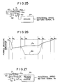
- Fig.26 shows the relationship between the established negative pressure and the position along the central cross-section of the stabilizing device 60 in the direction of motion of the medium.
- the ordinate expresses the position and the absissa expresses the negative pressure.
- the recording medium 1 is made of rigid material, that is, the recording medium is not deformed.
- a solid line l14 represents the negative pressure formed when the inclination angle is 0°, that is, the stabilizing device 60 is in a parallel relationship with the recording medium in the direction of motion thereof.
- the dotted line l15 represents the negative pressure formed when the inclination angle is ⁇ 1.
- Fig.27 shows the main structure of a contact stabilizing device of an 11th embodiment of the present invention.
- the present embodiment is different from the 10th embodiment in that an eccentric cam 71 is used in lieu of the piezoelectric element 63 to provide an inclination angle to a stabilizing device 70.
- a base block member 10 of the stabilizing device 70 is supported by a spherical bearing 61 and a stabilizing device supporting member 62 at the underside of the upstream end thereof in a cantilever manner in a manner similar to the 10th embodiment.
- the base block 10 abuts at the underside of the downstream end thereof on the eccentric cam 71 having a rotary shaft 72 at an off-centre position.
- the rotary shaft 72 of the eccentric cam 71 is rotated by means of a driving power source 73 comprising a motor, solenoid or the like.
- the driving power source 73 determines the displacement of the eccentric cam 71 in response to a rotational speed setting signal S2.
- the stabilizing device 70 thus moves away from the recording medium 1 to set an inclination angle ⁇ 1.
- an inclination angle is provided by displacing the downstream end of the base block member 10 of the stabilizing devices 60, 70 while the underside of the upstream end of the block member is supported.
- the upstream supporting means include a stabilizing device supporting member 62 and a spherical bearing 61 thereon as is disclosed in the present embodiment since the inclination angle required to increase the negative pressure is as small as 0.01°.
- the supporting means is not limited to those in the abovedescribed embodiments. It is evident that the supporting means may be a structure which provides a stable head contact by providing an inclination angle to the stabilizing device even when the rotational speed of the recording medium is changed.
Landscapes
- Magnetic Record Carriers (AREA)
- Supporting Of Heads In Record-Carrier Devices (AREA)
- Optical Record Carriers And Manufacture Thereof (AREA)
Applications Claiming Priority (8)
| Application Number | Priority Date | Filing Date | Title |
|---|---|---|---|
| JP6479488A JPH01237954A (ja) | 1988-03-18 | 1988-03-18 | 磁気ヘッド用パッド装置 |
| JP64794/88 | 1988-03-18 | ||
| JP176280/88 | 1988-07-14 | ||
| JP17628088A JP2731538B2 (ja) | 1988-07-14 | 1988-07-14 | 磁気ヘッド用パッド装置 |
| JP186100/88 | 1988-07-26 | ||
| JP18610088A JPH0235656A (ja) | 1988-07-26 | 1988-07-26 | 記録媒体規制装置 |
| JP48259/89 | 1989-02-28 | ||
| JP4825989A JPH02227867A (ja) | 1989-02-28 | 1989-02-28 | 磁気ヘッド用パッド装置 |
Publications (3)
| Publication Number | Publication Date |
|---|---|
| EP0333431A2 true EP0333431A2 (fr) | 1989-09-20 |
| EP0333431A3 EP0333431A3 (fr) | 1992-01-08 |
| EP0333431B1 EP0333431B1 (fr) | 1994-09-14 |
Family
ID=27462170
Family Applications (1)
| Application Number | Title | Priority Date | Filing Date |
|---|---|---|---|
| EP89302500A Expired - Lifetime EP0333431B1 (fr) | 1988-03-18 | 1989-03-14 | Appareil stabilisateur pour transducteur et support d'enregistrement |
Country Status (3)
| Country | Link |
|---|---|
| US (1) | US4998175A (fr) |
| EP (1) | EP0333431B1 (fr) |
| DE (1) | DE68918139T2 (fr) |
Cited By (3)
| Publication number | Priority date | Publication date | Assignee | Title |
|---|---|---|---|---|
| GB2220787B (en) * | 1988-06-15 | 1992-08-26 | Sony Corp | Stabilizer block for a disc drive unit |
| EP0502463A3 (en) * | 1991-03-04 | 1992-12-23 | Canon Kabushiki Kaisha | Recording or reproducing apparatus and head supporting device |
| EP0427239A3 (en) * | 1989-11-07 | 1993-04-28 | Canon Kabushiki Kaisha | Recording or reproducing apparatus |
Families Citing this family (3)
| Publication number | Priority date | Publication date | Assignee | Title |
|---|---|---|---|---|
| JP2830357B2 (ja) * | 1990-04-20 | 1998-12-02 | ソニー株式会社 | ヘッドの安定板及びその製造方法 |
| US5359590A (en) * | 1990-10-24 | 1994-10-25 | Canon Kabushiki Kaisha | Disc drive device having negative pressure pad |
| WO1997048095A1 (fr) | 1996-06-12 | 1997-12-18 | Imation Corp. | Stabilisation d'un support souple du type bernouilli pour l'ecriture par laser asservie |
Family Cites Families (15)
| Publication number | Priority date | Publication date | Assignee | Title |
|---|---|---|---|---|
| JPS5417708A (en) * | 1977-07-11 | 1979-02-09 | Toshiba Corp | Flexible disc recorder-reproducer |
| US4670806A (en) * | 1980-03-14 | 1987-06-02 | Memorex Corporation | Self loading slider for magnetic recording heads |
| US4375656A (en) * | 1980-10-09 | 1983-03-01 | International Business Machines Corporation | Magnetic head assembly with asymmetric slotted configuration |
| JPS5815870A (ja) * | 1981-07-21 | 1983-01-29 | 日立造船株式会社 | 船舶機関室の消火方法 |
| JPS5954071A (ja) * | 1982-09-22 | 1984-03-28 | Fujitsu Ltd | 磁気ヘツド安定支持装置 |
| JPS59215073A (ja) * | 1983-05-20 | 1984-12-04 | Sony Corp | 磁気記録再生装置 |
| JPS6061950A (ja) * | 1983-09-16 | 1985-04-09 | Toshiba Corp | 磁気ヘッド用パッド |
| JPS6093675A (ja) * | 1983-10-27 | 1985-05-25 | Canon Inc | フレキシブル・デイスク装置 |
| US4620250A (en) * | 1984-03-29 | 1986-10-28 | Eastman Kodak Company | Transducer-to-medium stabilizing device at negative attack angle with respect to medium |
| JPS60219672A (ja) * | 1984-04-17 | 1985-11-02 | Matsushita Electric Ind Co Ltd | 回転磁気シ−ト装置 |
| JPS61224174A (ja) * | 1985-03-29 | 1986-10-04 | Olympus Optical Co Ltd | 情報記録媒体規制装置 |
| US4652960A (en) * | 1985-08-05 | 1987-03-24 | Eastman Kodak Company | Flexible disk recording and/or reproducing apparatus |
| JPS6252759A (ja) * | 1985-09-02 | 1987-03-07 | Matsushita Electric Ind Co Ltd | 磁気記録再生装置 |
| JPH0719424B2 (ja) * | 1986-05-28 | 1995-03-06 | 帝人株式会社 | 磁気ディスク装置 |
| JPH01315061A (ja) * | 1988-06-15 | 1989-12-20 | Sony Corp | ヘッドの安定板構造 |
-
1989
- 1989-03-14 US US07/323,425 patent/US4998175A/en not_active Expired - Fee Related
- 1989-03-14 EP EP89302500A patent/EP0333431B1/fr not_active Expired - Lifetime
- 1989-03-14 DE DE68918139T patent/DE68918139T2/de not_active Expired - Fee Related
Cited By (4)
| Publication number | Priority date | Publication date | Assignee | Title |
|---|---|---|---|---|
| GB2220787B (en) * | 1988-06-15 | 1992-08-26 | Sony Corp | Stabilizer block for a disc drive unit |
| EP0427239A3 (en) * | 1989-11-07 | 1993-04-28 | Canon Kabushiki Kaisha | Recording or reproducing apparatus |
| US5477410A (en) * | 1989-11-07 | 1995-12-19 | Canon Kabushiki Kaisha | Recording or reproducing apparatus using a stabilizing pad |
| EP0502463A3 (en) * | 1991-03-04 | 1992-12-23 | Canon Kabushiki Kaisha | Recording or reproducing apparatus and head supporting device |
Also Published As
| Publication number | Publication date |
|---|---|
| DE68918139T2 (de) | 1995-01-12 |
| US4998175A (en) | 1991-03-05 |
| EP0333431A3 (fr) | 1992-01-08 |
| EP0333431B1 (fr) | 1994-09-14 |
| DE68918139D1 (de) | 1994-10-20 |
Similar Documents
| Publication | Publication Date | Title |
|---|---|---|
| JP3478556B2 (ja) | 磁気ヘッドスライダ | |
| US5086360A (en) | Constant flying height slider | |
| US20100046114A1 (en) | Control Flow Instability to Reduce Disk Flutter and Half Frequency Whirl | |
| EP0064390A1 (fr) | Support pour la stabilisation du mouvement d'un support d'enregistrement au dessus d'une tête magnétique | |
| JPS5817986B2 (ja) | 磁気変換器支持兼媒体安定化装置 | |
| US4620250A (en) | Transducer-to-medium stabilizing device at negative attack angle with respect to medium | |
| EP0333431B1 (fr) | Appareil stabilisateur pour transducteur et support d'enregistrement | |
| EP0123694A1 (fr) | Assemblage de tete rotative | |
| JPH0346114A (ja) | 磁気記録再生装置 | |
| US3912282A (en) | Recording and reproducing apparatus using flexible recording media | |
| US5012366A (en) | Magnetic head supporting device | |
| US6667855B2 (en) | Disk drive capable of avoiding the contact of disk and head slider in loading | |
| JP2737162B2 (ja) | ディスク装置 | |
| JPS62154364A (ja) | デイスク記録再生装置 | |
| JPH0235656A (ja) | 記録媒体規制装置 | |
| JPH0316130Y2 (fr) | ||
| JP2749418B2 (ja) | 磁気ヘッド支持装置 | |
| JPH045099Y2 (fr) | ||
| JP2728751B2 (ja) | 磁気ヘッド支持装置 | |
| JPH0256765A (ja) | 磁気ヘッド支持装置 | |
| JPS6226841Y2 (fr) | ||
| JPH01256086A (ja) | フレキシブルディスクカートリッジ | |
| JPH11339419A (ja) | 磁気ヘッド装置 | |
| JPH0218748A (ja) | 記録再生装置 | |
| JP2001351347A (ja) | ディスク記録再生装置のスライダ |
Legal Events
| Date | Code | Title | Description |
|---|---|---|---|
| PUAI | Public reference made under article 153(3) epc to a published international application that has entered the european phase |
Free format text: ORIGINAL CODE: 0009012 |
|
| AK | Designated contracting states |
Kind code of ref document: A2 Designated state(s): CH DE FR GB IT LI |
|
| PUAL | Search report despatched |
Free format text: ORIGINAL CODE: 0009013 |
|
| AK | Designated contracting states |
Kind code of ref document: A3 Designated state(s): CH DE FR GB IT LI |
|
| 17P | Request for examination filed |
Effective date: 19920530 |
|
| 17Q | First examination report despatched |
Effective date: 19920929 |
|
| GRAA | (expected) grant |
Free format text: ORIGINAL CODE: 0009210 |
|
| ITF | It: translation for a ep patent filed | ||
| AK | Designated contracting states |
Kind code of ref document: B1 Designated state(s): CH DE FR GB IT LI |
|
| ET | Fr: translation filed | ||
| REF | Corresponds to: |
Ref document number: 68918139 Country of ref document: DE Date of ref document: 19941020 |
|
| PLBE | No opposition filed within time limit |
Free format text: ORIGINAL CODE: 0009261 |
|
| STAA | Information on the status of an ep patent application or granted ep patent |
Free format text: STATUS: NO OPPOSITION FILED WITHIN TIME LIMIT |
|
| 26N | No opposition filed | ||
| REG | Reference to a national code |
Ref country code: GB Ref legal event code: IF02 |
|
| PGFP | Annual fee paid to national office [announced via postgrant information from national office to epo] |
Ref country code: FR Payment date: 20020312 Year of fee payment: 14 |
|
| PGFP | Annual fee paid to national office [announced via postgrant information from national office to epo] |
Ref country code: GB Payment date: 20020313 Year of fee payment: 14 |
|
| PGFP | Annual fee paid to national office [announced via postgrant information from national office to epo] |
Ref country code: DE Payment date: 20020327 Year of fee payment: 14 |
|
| PGFP | Annual fee paid to national office [announced via postgrant information from national office to epo] |
Ref country code: CH Payment date: 20020328 Year of fee payment: 14 |
|
| PG25 | Lapsed in a contracting state [announced via postgrant information from national office to epo] |
Ref country code: GB Free format text: LAPSE BECAUSE OF NON-PAYMENT OF DUE FEES Effective date: 20030314 |
|
| PG25 | Lapsed in a contracting state [announced via postgrant information from national office to epo] |
Ref country code: LI Free format text: LAPSE BECAUSE OF NON-PAYMENT OF DUE FEES Effective date: 20030331 Ref country code: CH Free format text: LAPSE BECAUSE OF NON-PAYMENT OF DUE FEES Effective date: 20030331 |
|
| PG25 | Lapsed in a contracting state [announced via postgrant information from national office to epo] |
Ref country code: DE Free format text: LAPSE BECAUSE OF NON-PAYMENT OF DUE FEES Effective date: 20031001 |
|
| GBPC | Gb: european patent ceased through non-payment of renewal fee |
Effective date: 20030314 |
|
| REG | Reference to a national code |
Ref country code: CH Ref legal event code: PL |
|
| PG25 | Lapsed in a contracting state [announced via postgrant information from national office to epo] |
Ref country code: FR Free format text: LAPSE BECAUSE OF NON-PAYMENT OF DUE FEES Effective date: 20031127 |
|
| REG | Reference to a national code |
Ref country code: FR Ref legal event code: ST |
|
| PG25 | Lapsed in a contracting state [announced via postgrant information from national office to epo] |
Ref country code: IT Free format text: LAPSE BECAUSE OF NON-PAYMENT OF DUE FEES;WARNING: LAPSES OF ITALIAN PATENTS WITH EFFECTIVE DATE BEFORE 2007 MAY HAVE OCCURRED AT ANY TIME BEFORE 2007. THE CORRECT EFFECTIVE DATE MAY BE DIFFERENT FROM THE ONE RECORDED. Effective date: 20050314 |