EP0124483A2 - Akustisches Meldethermometer für einen Kochgefässdeckel - Google Patents
Akustisches Meldethermometer für einen Kochgefässdeckel Download PDFInfo
- Publication number
- EP0124483A2 EP0124483A2 EP84810197A EP84810197A EP0124483A2 EP 0124483 A2 EP0124483 A2 EP 0124483A2 EP 84810197 A EP84810197 A EP 84810197A EP 84810197 A EP84810197 A EP 84810197A EP 0124483 A2 EP0124483 A2 EP 0124483A2
- Authority
- EP
- European Patent Office
- Prior art keywords
- housing
- magnet
- acoustic
- warning
- sensor
- Prior art date
- Legal status (The legal status is an assumption and is not a legal conclusion. Google has not performed a legal analysis and makes no representation as to the accuracy of the status listed.)
- Granted
Links
Images




Classifications
-
- A—HUMAN NECESSITIES
- A47—FURNITURE; DOMESTIC ARTICLES OR APPLIANCES; COFFEE MILLS; SPICE MILLS; SUCTION CLEANERS IN GENERAL
- A47J—KITCHEN EQUIPMENT; COFFEE MILLS; SPICE MILLS; APPARATUS FOR MAKING BEVERAGES
- A47J27/00—Cooking-vessels
- A47J27/21—Water-boiling vessels, e.g. kettles
- A47J27/212—Water-boiling vessels, e.g. kettles with signaling means, e.g. whistling kettles
-
- G—PHYSICS
- G01—MEASURING; TESTING
- G01K—MEASURING TEMPERATURE; MEASURING QUANTITY OF HEAT; THERMALLY-SENSITIVE ELEMENTS NOT OTHERWISE PROVIDED FOR
- G01K5/00—Measuring temperature based on the expansion or contraction of a material
- G01K5/48—Measuring temperature based on the expansion or contraction of a material the material being a solid
- G01K5/56—Measuring temperature based on the expansion or contraction of a material the material being a solid constrained so that expansion or contraction causes a deformation of the solid
- G01K5/62—Measuring temperature based on the expansion or contraction of a material the material being a solid constrained so that expansion or contraction causes a deformation of the solid the solid body being formed of compounded strips or plates, e.g. bimetallic strip
- G01K5/70—Measuring temperature based on the expansion or contraction of a material the material being a solid constrained so that expansion or contraction causes a deformation of the solid the solid body being formed of compounded strips or plates, e.g. bimetallic strip specially adapted for indicating or recording
-
- A—HUMAN NECESSITIES
- A47—FURNITURE; DOMESTIC ARTICLES OR APPLIANCES; COFFEE MILLS; SPICE MILLS; SUCTION CLEANERS IN GENERAL
- A47J—KITCHEN EQUIPMENT; COFFEE MILLS; SPICE MILLS; APPARATUS FOR MAKING BEVERAGES
- A47J45/00—Devices for fastening or gripping kitchen utensils or crockery
- A47J45/06—Handles for hollow-ware articles
- A47J45/068—Handles having indicating means, e.g. for temperature
-
- A—HUMAN NECESSITIES
- A47—FURNITURE; DOMESTIC ARTICLES OR APPLIANCES; COFFEE MILLS; SPICE MILLS; SUCTION CLEANERS IN GENERAL
- A47J—KITCHEN EQUIPMENT; COFFEE MILLS; SPICE MILLS; APPARATUS FOR MAKING BEVERAGES
- A47J45/00—Devices for fastening or gripping kitchen utensils or crockery
- A47J45/06—Handles for hollow-ware articles
- A47J45/07—Handles for hollow-ware articles of detachable type
- A47J45/074—Knobs, e.g. for lids
Definitions
- Acoustic warning devices for cooking vessel lids consist of a whistle adaptable to the lid of the container and which operates under the effect of steam passing through it when heated liquid in the container comes to a boil and when , therefore, the pressure of the vapor in the container suddenly increases and forces the vapor to escape through the whistle.
- these devices have the disadvantage of only indicating the boiling temperature, whereas in practice it would be useful to warn the user when a chosen temperature, for example 30 to 40 ° C ( end of rapid heating) and / or a different temperature, for example an end of cooking temperature (950 for ordinary vessels or 120 to 130 ° C for vessels commonly called pressure steamers).
- the present invention aims to provide an acoustic warning thermometric device for a cooking vessel cover which overcomes the indicated drawbacks of known devices - and its subject is an acoustic warning thermometric device for a cooking container cover, which conforms to claim 1.
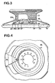
- the first embodiment includes a housing 11 made of plastic material such as polyethersulfone, intended to be fixed on a metal cover of a cooking container, partially visible at 12, to form both a cover button and a temperature indicator .
- the housing 11 has inside a chamber 13 which is closed, at the bottom, by a bottom 14 forming part of the housing 11, and at the top by a window 15.
- This glass is pressed into place against the upper part of the body 11 by a metallized bezel 16, snapping into a groove in the housing 11.
- a sealing ring 17 is pressed by the bezel 16 to close any communication between the edge of the glass 15 and the upper part of the body 11.
- the housing 11 has a skirt 18 extending outside- and obliquely down. When it is desired to fix the housing 11 to the cover 12, it is placed as shown in FIG. 1, on the central part of the cover 12, so that it rests on this cover by the circular outer edge 19 of the skirt 18. The bottom 14 is then located at a certain distance above the cover 12.
- a piece of stainless steel 20 having, in plan view (fig. 2) a hexagonal shape, is fixed to the cover 12, by welding.
- Three of the sides of the part 20 located at 120 0 from each other are each provided with an inwardly curved part 21a, 21b, 22a, 22b, 23a, 23b, separated by a V-shaped part to form position stop.
- the housing 11 has in its lateral part, but near the bottom 14, three pairs of fingers 24a, 24b, 25a, 25b, 26a, 26b between which the V-shaped part engages.
- the skirt 18 During the movement of the bottom 14 until it makes contact with the cover 12, the skirt 18 remains constantly in contact with the cover by its edge 19, but elastically deforms to pass from the position shown shown in fig. 1 to that visible in FIG. 2. This skirt thus forms a closed chamber inside which the fixing means which have just been described are protected from water when the cover is cleaned.
- a bimetallic spiral thermometric element 27 is disposed flat against the inner face of the bottom 14. Its internal end is fixed to the body 11 while its external end is free and secured to a vertical pin 28.
- the finger 28 is engaged in a radial groove 32 provided at the base of the lower part 29 of the movable assembly.
- the upper part 33 of the movable crew has the shape of a disc which is visible through the glass 15.
- a temperature scale is preferably provided on the internal face of the glass 15, while the visible face of the disc 33 has a mark moving opposite this scale, to indicate the temperature measured by element 27.
- thermometric metallic element 27 is negligible and has no appreciable effect on the accuracy of the temperature indicated by the device. It has also shown that the thermal transmission from the cover 12 to the element 27, by conduction through the bottom 14, is excellent thanks to the good contact between this bottom and the cover. Moreover, it is advantageous to provide, as shown in the drawing, that the bottom 14 is thinner than the side wall of the housing 11. This facilitates the adaptation of the bottom to the shape of the cover and the transmission of heat to through him. In addition, we will advantageously choose a dark color for the case (preferably black) which favors the transfer of radiant heat.
- the device described also comprises means which will now be described and which serve to give an audible signal when the temperature measured by the element 27 reaches a value chosen in advance.
- This housing has a groove 36 in which a movable part 37, made of plastic, can slide radially, in which a small permanent magnet 38 is housed.
- This body 37 has at its upper part a finger 39 intended to cooperate with a cam 40 having the shape which can be seen in FIG. 2.
- the position of the organs shown in FIG. 2 corresponds to a temperature in the container of 30 to 4CPC which represents the end of rapid heating of the food.
- the finger 39 is engaged between two parts of the cam 40 which form an oblique channel 41.
- the major part of the cam 40 is of circular shape.
- Reed which includes a fixed blade and a mobile blade made of ferro-magnetic metal, these two blades being enclosed in a waterproof capsule.
- the switch 43 When the magnet 38 is as close as possible to the switch 43, the latter closes.
- this switch opens.
- This switch is disposed in a housing provided in a circular cursor 44 engaged on the periphery of the body 11 and capable of turning with gentle friction on the peri the body of this body. Inside the cursor 44, there is an electric battery 45 and a buzzer 46.
- the closing of the switch 43 has the effect of actuating the buzzer, the sound of which passes outside through orifices 47 of the cursor.
- This cursor and with it the organs it contains constitute an acoustic sensor-alarm.
- a plug 48 is provided to allow the replacement of the battery 45.
- the cursor 44 has been shown in a position corresponding to the temperature of 30 0 , that is to say at the time when the user must be informed that this temperature is reached.
- the predetermined temperature for example, 95 ° C.
- the user need only rotate the cursor 44 so that his index finger 49 is opposite this temperature.
- this temperature is reached, this are then the means arranged in the housing 35 which will control the acoustic signal.
- Figs. 5 to 9 represent the cam 40 in different angular positions corresponding to measured temperatures ranging from ambient temperature (FIG. 5) to a maximum temperature which can be 120 ° C. for example.
- the cam In fig. 5, the cam is in the position corresponding to the ambient temperature, the finger 39 is at the entrance to the channel 41 and occupies its position closest to the axis of the device. Its magnet 38 (fig. 1) has no effect on the switch 43.
- Fig. 6 shows the position of the members when the end of rapid heating temperature (for example 30 ° C. ) is reached.
- the finger 39 followed the channel 41 and was therefore forced by the cam 40 to come to occupy its position closest to the switch 43.
- the magnet 38 closes the contact of the switch 43 and the acoustic signal is given by the buzzer 46.
- the user being warned by the signal, angularly moves the cursor 44 from the position where it was located opposite 34 to bring it opposite 35, which corresponds to a cooking temperature of, for example, 95 ° C.
- the moving element continues to rotate, the buzzer having stopped functioning and the position according to FIG. 7.
- the finger 39a 35 which is in contact with the inner side of the cam 40, while the finger 3 9 is in contact with the outer side of this cam, is in its position closest to the axis of rotation.
- the moving element continuing to rotate with the temperature increasing the finger 39 arrives at the entrance to the channel 41, which leads it to the position shown in FIG. 8 where it is then in its position furthest from the axis of rotation and, consequently, in its position closest to the switch 43. Therefore, the buzzer operates again to signal that the maximum temperature is reached. If the temperature continues to rise to, for example, 120 ° C., the members take the position shown in FIG. 7, for which the buzzer continues to operate. The user then stops the heating, the cam 40 rotates in the opposite direction to the arrows indicated and gradually returns to the position according to FIG. 5.
- the device described makes it possible to acoustically signal when the temperature of the container reaches one or the other of two predetermined temperatures corresponding to the angular position of 34 and 35.
- the body of the device comprises a metal box 50 on the side wall of which are snap-fastened, on the one hand a skirt 18a similar to 18, and an upper ring 51 of plastic material on which is snapped a telescope 52 after the upper end portion has been wound up annularly of 50, as seen in 53.
- This part thus wound comes to hold in place the glass 15a similar to 15.
- Sealing rings not shown are obviously provided to seal the assembly formed by the glass 15a and the box 50.
- the means for fixing the housing 11 to the cover, not shown in FIGS. 10 and 11 are different from those described in connection with the first embodiment.
- the bottom 50a of the box 50 has, in its central part, a recess 50b in which are engaged means for fixing the device to the container lid.
- These means can be, for example, those which will be described with reference to Figures 12 - 14 or 15 and 16.
- This embodiment still differs from the first in that the parts 34 and 35 in which are mounted sliding the small magnets are not fixed to the box 11 itself, but are integral with a cylindrical body 50c housed in the box 50 between the bottom 50a and the glass 15a.
- the parts corresponding to 34 and 35 are indicated in 34a and 35a.
- the bottom 50a is thinner than the cylindrical part of the box 50, to allow this bottom to deform elastically when it is pressed against the cover, so that it can exactly match the shape of the latter and thus ensure good thermal transmission to the spiral thermometric element 27a which is arranged in contact with the inner face of this bottom.
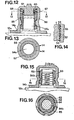
- Figs. 12 - 14 show a binding of this type, but provided with safety means consisting of a torque limiter. It has been admitted that in these figures the housing is of the same type as that according to FIG. 1, with however some differences which will be mentioned.
- this fixing takes place by means of a threaded rod 54a welded to the cover 12a.
- a nut 55 is screwed onto the thread of the rod 54a.
- This nut is disposed in a central recess of a protuberance 56 secured to the bottom 14a of the housing such as 11.
- Torque limiting means are provided between the protuberance 56 and the nut 55; they include a toothing 57 formed in the annular upper face of the nut 55.
- the teeth of this toothing have a radial flank and an oblique flank, as can be seen in FIG. 14.
- These means also include a washer 58 arranged opposite the toothing 57 and having, in its face looking at the nut 55 a toothing 59 having teeth also having a radial flank and an oblique flank, arranged as shown in the figure 14.
- a washer 60 forming a compression spring is disposed between the toothed washer 58 and the bottom 61 of the protuberance 56. The operation is as follows: when the nut 55 is screwed onto the threaded rod 54a to fix the housing to the cover and to apply the bottom 61 of the box 50 strongly to the cover, as long as the torque exerted on the housing does not reach a predetermined value, the spring washer 60 keeps the teeth 57 and 59 in engagement, the oblique sides of the two teeth then being in drive contact. As soon as the fixed limit torque is reached, the spring washer 60 gives way and the toothing 59 ceases to drive the toothing 57 and slides on it. Of course, the washer 58 is fixed in rotation relative to the protuberance 56 of the housing.
- the threaded rod 54b is welded to the cover 12b and a nut 62 is screwed onto the thread of this rod 54b.
- This nut is disposed in a central recess of a protuberance 63 secured to the bottom 14b of the housing.
- the top of the protrusion 63 has a pivot 31a similar to 31 in FIG. 1.
- the periphery of the nut 62 is wavy as shown exaggeratedly at 64 in FIG. 16.
- the inner surface of the protuberance 63 has a corresponding corrugated shape 65.
- the nut 62 is rotated by the body of the device, as long as the torque exerted on this body does not exceed a predetermined maximum. Once this maximum is reached, if the housing is continued to rotate, the plastic material of the corrugations 65 of the protuberance 63 deforms elastically and these corrugations no longer entail the nut 60 whose corrugations 64 then slide in this protuberance 63 .
- This arrangement therefore constitutes a torque limiter preventing damage to the device and the cover by acting too forcefully on the housing to screw the nut 62 onto the threaded rod 54b.
- the mobile assembly comprises, as in fig. 1 two parts 29a, 30a fitted one on the other and rotating on a pivot 31b.
- the part 30a is devoid of a cam such as 40 and there are no parts such as 34 and 35 in which a magnet 38 is arranged to slide radially.
- a small permanent magnet 38a ⁇ is housed in a part of the cylindrical wall of the part 30a and therefore rotates with the moving element.
- a cursor 44a of general shape similar to 44 of fig.1 is adapted on the housing to be able to be moved around the periphery thereof. Inside the cursor 44a, there is disposed a switch of the Reed type 43a arranged to close when the magnet 38a is in radial alignment with it. In 46a is the buzzer ordered by 43a but here the order takes place a little differently.
- a relay 66 is provided which is energized when the contact of 43a closes. This relay controls a closing contact 67 which ensures that it remains energized after the contact of 43a has opened when the magnet 38a ceases to be opposite 43a. So when the measured temperature reaches, for example, 30 ° which is the temperature corresponding to the position of the cursor 44a in FIG.
- the magnet '38a actuates the switch 43a, the relay 66 is energized, the buzzer 46a operates. Thanks to the relay 66, this buzzer continues to operate even when the temperature continues to increase and the magnet 38a is no longer in front of the cursor 44a. The user is therefore warned that the first rapid heating end temperature has been reached and, to stop the acoustic signal, it suffices to press a button 68, to cause the opening of the relay holding circuit 66. If the user now wants to be notified when another temperature is reached, for example 75 ° in the case of fig. 18, it suffices to rotate the cursor 44a to bring it into the position shown in phantom for the buzzer 46a to operate when this temperature of 75 ° is reached. It can be seen that this embodiment makes it possible to provide an acoustic signal for any temperature chosen by the operator.
Landscapes
- Engineering & Computer Science (AREA)
- Food Science & Technology (AREA)
- Physics & Mathematics (AREA)
- General Physics & Mathematics (AREA)
- Cookers (AREA)
- Measuring Temperature Or Quantity Of Heat (AREA)
- Thermally Insulated Containers For Foods (AREA)
- Transducers For Ultrasonic Waves (AREA)
- Electrophonic Musical Instruments (AREA)
- Fittings On The Vehicle Exterior For Carrying Loads, And Devices For Holding Or Mounting Articles (AREA)
- Baking, Grill, Roasting (AREA)
- Emergency Alarm Devices (AREA)
- Burglar Alarm Systems (AREA)
- Glass Compositions (AREA)
Priority Applications (1)
| Application Number | Priority Date | Filing Date | Title |
|---|---|---|---|
| AT84810197T ATE31222T1 (de) | 1983-04-29 | 1984-04-26 | Akustisches meldethermometer fuer einen kochgefaessdeckel. |
Applications Claiming Priority (2)
| Application Number | Priority Date | Filing Date | Title |
|---|---|---|---|
| CH233583 | 1983-04-29 | ||
| CH2335/83 | 1983-04-29 |
Publications (3)
| Publication Number | Publication Date |
|---|---|
| EP0124483A2 true EP0124483A2 (de) | 1984-11-07 |
| EP0124483A3 EP0124483A3 (en) | 1985-01-09 |
| EP0124483B1 EP0124483B1 (de) | 1987-12-02 |
Family
ID=4231409
Family Applications (1)
| Application Number | Title | Priority Date | Filing Date |
|---|---|---|---|
| EP84810197A Expired EP0124483B1 (de) | 1983-04-29 | 1984-04-26 | Akustisches Meldethermometer für einen Kochgefässdeckel |
Country Status (14)
| Country | Link |
|---|---|
| US (1) | US4571580A (de) |
| EP (1) | EP0124483B1 (de) |
| JP (1) | JPS60122524A (de) |
| KR (1) | KR910001170B1 (de) |
| AT (1) | ATE31222T1 (de) |
| AU (1) | AU560856B2 (de) |
| CA (1) | CA1227052A (de) |
| DE (1) | DE3467930D1 (de) |
| ES (1) | ES8503847A1 (de) |
| GR (1) | GR81993B (de) |
| IL (1) | IL71596A (de) |
| MX (1) | MX156353A (de) |
| PT (1) | PT78513B (de) |
| ZA (1) | ZA843105B (de) |
Cited By (3)
| Publication number | Priority date | Publication date | Assignee | Title |
|---|---|---|---|---|
| EP0364684A1 (de) * | 1988-10-18 | 1990-04-25 | AMC International Alfa Metalcraft Corporation AG | Vorrichtung zur Anzeige eines Betriebszustandes eines Gargefässes |
| GB2429285A (en) * | 2005-08-19 | 2007-02-21 | Strix Ltd | Temperature indicators |
| EP1892510A1 (de) * | 2006-08-24 | 2008-02-27 | Rüeger S.A. | Vorrichtung zur Temperaturmessung |
Families Citing this family (11)
| Publication number | Priority date | Publication date | Assignee | Title |
|---|---|---|---|---|
| JPS62134508U (de) * | 1986-02-17 | 1987-08-25 | ||
| JPS63166117U (de) * | 1987-04-17 | 1988-10-28 | ||
| JPH0716018Y2 (ja) * | 1988-05-19 | 1995-04-12 | スズキ株式会社 | 排気マニホルドの遮熱板 |
| US5471912A (en) * | 1994-12-28 | 1995-12-05 | Lin; Chia-Meng | Vessel having boiling indicating device |
| IT1296831B1 (it) * | 1997-12-02 | 1999-08-02 | Guatta Andrea S P A | Apparecchio per la misurazione e la segnalazione della temperatura interna di un recipiente |
| US7028605B2 (en) * | 2003-05-27 | 2006-04-18 | Regal Ware, Inc. | Audible signal valve knob with timer |
| US20050205577A1 (en) * | 2004-03-16 | 2005-09-22 | Park Soonkwan | Cookware lid assembly with sealing band and whistling handle |
| US7387438B2 (en) * | 2005-11-02 | 2008-06-17 | Robert Parker | Reusable, resettable, critical temperature indicator |
| FR2940900B1 (fr) * | 2009-01-15 | 2012-01-06 | Seb Sa | Autocuiseur muni d'un dispositif electronique d'information |
| CN110209218B (zh) * | 2018-12-12 | 2024-03-29 | 华帝股份有限公司 | 磁悬浮测温装置及烹饪设备 |
| WO2020126934A1 (de) * | 2018-12-19 | 2020-06-25 | Amc International Alfa Metalcraft Corporation Ag | Vorrichtung zur bestimmung oder überwachung zumindest eines betriebszustandes eines kochgefässes |
Family Cites Families (4)
| Publication number | Priority date | Publication date | Assignee | Title |
|---|---|---|---|---|
| US3130285A (en) * | 1960-03-11 | 1964-04-21 | Honeywell Regulator Co | Thermally actuated dual magnetic switch with shunt and temperature compensation |
| NL165878C (nl) * | 1975-02-14 | 1981-05-15 | Eerste Nl Fab Manometers | Regelinrichting voor het instellen van de water tem- peratuur van een centrale verwarmingsketel in af- hankelijkheid van de buitentemperatuur. |
| DE2909129A1 (de) * | 1979-03-08 | 1980-09-11 | Horst Schultz | Verfahren und vorrichtung zum elektrischen uebertragen und anzeigen von kochtemperaturen |
| FR2535845A1 (fr) * | 1982-11-08 | 1984-05-11 | Levalois Daniel | Dispositif de commande thermodeclenchable a element mobile de commande et ustensile menager ou de cuisine formant dispositif avertisseur sonore utilisant ce dispositif de commande |
-
1984
- 1984-04-18 US US06/601,659 patent/US4571580A/en not_active Expired - Fee Related
- 1984-04-19 AU AU27155/84A patent/AU560856B2/en not_active Ceased
- 1984-04-20 IL IL71596A patent/IL71596A/xx not_active IP Right Cessation
- 1984-04-26 AT AT84810197T patent/ATE31222T1/de not_active IP Right Cessation
- 1984-04-26 EP EP84810197A patent/EP0124483B1/de not_active Expired
- 1984-04-26 DE DE8484810197T patent/DE3467930D1/de not_active Expired
- 1984-04-26 ZA ZA843105A patent/ZA843105B/xx unknown
- 1984-04-27 JP JP59087652A patent/JPS60122524A/ja active Pending
- 1984-04-27 PT PT78513A patent/PT78513B/pt unknown
- 1984-04-27 KR KR1019840002256A patent/KR910001170B1/ko not_active Expired
- 1984-04-27 GR GR74540A patent/GR81993B/el unknown
- 1984-04-27 ES ES531964A patent/ES8503847A1/es not_active Expired
- 1984-04-27 CA CA000453038A patent/CA1227052A/fr not_active Expired
- 1984-04-30 MX MX201199A patent/MX156353A/es unknown
Cited By (5)
| Publication number | Priority date | Publication date | Assignee | Title |
|---|---|---|---|---|
| EP0364684A1 (de) * | 1988-10-18 | 1990-04-25 | AMC International Alfa Metalcraft Corporation AG | Vorrichtung zur Anzeige eines Betriebszustandes eines Gargefässes |
| JPH0320630A (ja) * | 1988-10-18 | 1991-01-29 | Alfa Inst Fuer Hauswirtschaft Prod & Verfahren Entwickl Gmbh | 槽の操作状態を表示する装置 |
| GB2429285A (en) * | 2005-08-19 | 2007-02-21 | Strix Ltd | Temperature indicators |
| EP1892510A1 (de) * | 2006-08-24 | 2008-02-27 | Rüeger S.A. | Vorrichtung zur Temperaturmessung |
| WO2008023353A1 (fr) | 2006-08-24 | 2008-02-28 | Rüeger S.A. | Dispositif de mesure de température |
Also Published As
| Publication number | Publication date |
|---|---|
| ES531964A0 (es) | 1985-03-16 |
| KR840008581A (ko) | 1984-12-17 |
| US4571580A (en) | 1986-02-18 |
| ES8503847A1 (es) | 1985-03-16 |
| AU2715584A (en) | 1984-11-01 |
| JPS60122524A (ja) | 1985-07-01 |
| AU560856B2 (en) | 1987-04-16 |
| IL71596A (en) | 1986-08-31 |
| CA1227052A (fr) | 1987-09-22 |
| PT78513B (fr) | 1986-05-28 |
| GR81993B (de) | 1984-12-12 |
| KR910001170B1 (ko) | 1991-02-25 |
| DE3467930D1 (en) | 1988-01-14 |
| MX156353A (es) | 1988-08-10 |
| IL71596A0 (en) | 1984-07-31 |
| PT78513A (fr) | 1984-05-01 |
| ATE31222T1 (de) | 1987-12-15 |
| EP0124483B1 (de) | 1987-12-02 |
| EP0124483A3 (en) | 1985-01-09 |
| ZA843105B (en) | 1984-11-28 |
Similar Documents
| Publication | Publication Date | Title |
|---|---|---|
| EP0124483B1 (de) | Akustisches Meldethermometer für einen Kochgefässdeckel | |
| EP2016874B1 (de) | Schnellkochtopf, der mit einem Informationsfenster ausgestattet ist | |
| EP2934252B1 (de) | Elektrische speisenzubereitungsvorrichtung mit einem arbeitsbehälter und vorrichtung zum erwärmen des inhalts des arbeitsbehälters | |
| EP1344476B1 (de) | Dampfdruckkochgerät mit einer drehenden Verriegelungsvorrichtung | |
| EP2338391A1 (de) | Elektrogerät zur Nahrungsmittelzubereitung | |
| EP2687132B1 (de) | Druckkochgerät mit verbesserter Bedienungsvorrichtung | |
| EP2624728B1 (de) | Schnellkochtopf mit entkuppelbarem steuerelement | |
| EP0761558B1 (de) | Vorrichtung zum Verschliessen eines Behälters und zur Abgabe des Behälterinhalts | |
| EP2923621B1 (de) | Elektrohaushaltsgerät zur essenszubereitung, das einen behälter umfasst, der mit einem abnehmbaren deckel verschlossen ist, der mit einer sicherheitsvorrichtung kombiniert ist | |
| FR2984988A1 (fr) | Soupape de purge pour appareil de cuisson sous pression | |
| EP2805649A1 (de) | Kochtopf, der ein dichtes Steuermodul umfasst | |
| EP1734850B1 (de) | Elektrisches gerät zum erhitzen von flüssigkeiten | |
| EP0124484A2 (de) | Thermometer für ein Kochgefäss | |
| FR2535190A3 (fr) | Dispositif de couvercle pour des recipients, notamment des recipients de cuisson tels que des casseroles comportant un element de couvercle en un materiau metallique muni d'au moins un organe de prehension et comportant des moyens de mesure thermometrique | |
| EP1435815B1 (de) | Kochgerät mit einem gefäss, umfassend eine ablassvorrichtung mit einem wärmesicherheitsventil | |
| EP0022020B1 (de) | Druckbegrenzungsventil für ein unter Druck arbeitendes Haushaltsgerät | |
| EP0001960A1 (de) | Vorrichtung zum Anbringen eines Apparates an einem Druckbehälter | |
| FR2575089A1 (fr) | Diffuseur en matiere plastique pour recipient sous pression | |
| FR2775178A1 (fr) | Appareil electrique de cuisson, en particulier friteuse | |
| FR2535598A1 (fr) | Dispositif formant avertisseur sonore associable a un recipient hermetiquement ferme muni d'une soupape | |
| FR2573271A3 (fr) | Appareil electrique, en particulier chauffe-eau, muni d'une calotte protectrice et d'un organe de regulation thermostatique | |
| FR2515814A1 (fr) | Profondimetre ou compteur de profondeur pour plongee sous-marine | |
| BE460948A (de) | ||
| CH137801A (fr) | Remontoir pour pièce d'horlogerie. | |
| FR2535845A1 (fr) | Dispositif de commande thermodeclenchable a element mobile de commande et ustensile menager ou de cuisine formant dispositif avertisseur sonore utilisant ce dispositif de commande |
Legal Events
| Date | Code | Title | Description |
|---|---|---|---|
| PUAI | Public reference made under article 153(3) epc to a published international application that has entered the european phase |
Free format text: ORIGINAL CODE: 0009012 |
|
| PUAL | Search report despatched |
Free format text: ORIGINAL CODE: 0009013 |
|
| AK | Designated contracting states |
Designated state(s): AT BE CH DE FR GB IT LI LU NL SE |
|
| AK | Designated contracting states |
Designated state(s): AT BE CH DE FR GB IT LI LU NL SE |
|
| 17P | Request for examination filed |
Effective date: 19850215 |
|
| 17Q | First examination report despatched |
Effective date: 19860519 |
|
| GRAA | (expected) grant |
Free format text: ORIGINAL CODE: 0009210 |
|
| AK | Designated contracting states |
Kind code of ref document: B1 Designated state(s): AT BE CH DE FR GB IT LI LU NL SE |
|
| REF | Corresponds to: |
Ref document number: 31222 Country of ref document: AT Date of ref document: 19871215 Kind code of ref document: T |
|
| ITF | It: translation for a ep patent filed | ||
| REF | Corresponds to: |
Ref document number: 3467930 Country of ref document: DE Date of ref document: 19880114 |
|
| PG25 | Lapsed in a contracting state [announced via postgrant information from national office to epo] |
Ref country code: LU Free format text: LAPSE BECAUSE OF NON-PAYMENT OF DUE FEES Effective date: 19880430 |
|
| PLBE | No opposition filed within time limit |
Free format text: ORIGINAL CODE: 0009261 |
|
| STAA | Information on the status of an ep patent application or granted ep patent |
Free format text: STATUS: NO OPPOSITION FILED WITHIN TIME LIMIT |
|
| 26N | No opposition filed | ||
| PG25 | Lapsed in a contracting state [announced via postgrant information from national office to epo] |
Ref country code: GB Effective date: 19890426 Ref country code: AT Effective date: 19890426 |
|
| PG25 | Lapsed in a contracting state [announced via postgrant information from national office to epo] |
Ref country code: SE Effective date: 19890427 |
|
| PG25 | Lapsed in a contracting state [announced via postgrant information from national office to epo] |
Ref country code: LI Effective date: 19890430 Ref country code: CH Effective date: 19890430 Ref country code: BE Effective date: 19890430 |
|
| BERE | Be: lapsed |
Owner name: MESINVEST N.V. Effective date: 19890430 |
|
| PG25 | Lapsed in a contracting state [announced via postgrant information from national office to epo] |
Ref country code: NL Effective date: 19891101 |
|
| NLV4 | Nl: lapsed or anulled due to non-payment of the annual fee | ||
| GBPC | Gb: european patent ceased through non-payment of renewal fee | ||
| PG25 | Lapsed in a contracting state [announced via postgrant information from national office to epo] |
Ref country code: FR Free format text: LAPSE BECAUSE OF NON-PAYMENT OF DUE FEES Effective date: 19891228 |
|
| REG | Reference to a national code |
Ref country code: CH Ref legal event code: PL |
|
| PG25 | Lapsed in a contracting state [announced via postgrant information from national office to epo] |
Ref country code: DE Effective date: 19900103 |
|
| REG | Reference to a national code |
Ref country code: FR Ref legal event code: ST |
|
| EUG | Se: european patent has lapsed |
Ref document number: 84810197.8 Effective date: 19900412 |