EP0124632A1 - Générateur pour pompes à chaleur à sorption - Google Patents
Générateur pour pompes à chaleur à sorption Download PDFInfo
- Publication number
- EP0124632A1 EP0124632A1 EP83104514A EP83104514A EP0124632A1 EP 0124632 A1 EP0124632 A1 EP 0124632A1 EP 83104514 A EP83104514 A EP 83104514A EP 83104514 A EP83104514 A EP 83104514A EP 0124632 A1 EP0124632 A1 EP 0124632A1
- Authority
- EP
- European Patent Office
- Prior art keywords
- expeller
- pins
- housing wall
- wall section
- cylindrical housing
- Prior art date
- Legal status (The legal status is an assumption and is not a legal conclusion. Google has not performed a legal analysis and makes no representation as to the accuracy of the status listed.)
- Withdrawn
Links
Images


Classifications
-
- F—MECHANICAL ENGINEERING; LIGHTING; HEATING; WEAPONS; BLASTING
- F25—REFRIGERATION OR COOLING; COMBINED HEATING AND REFRIGERATION SYSTEMS; HEAT PUMP SYSTEMS; MANUFACTURE OR STORAGE OF ICE; LIQUEFACTION SOLIDIFICATION OF GASES
- F25B—REFRIGERATION MACHINES, PLANTS OR SYSTEMS; COMBINED HEATING AND REFRIGERATION SYSTEMS; HEAT PUMP SYSTEMS
- F25B33/00—Boilers; Analysers; Rectifiers
Definitions
- the invention relates to an expeller for sorption heat pumps for expelling the working medium supplied in a solution, with a vertical expeller housing arranged in a heating chamber above a burner, which has a cylindrical housing wall section to which wall projections that increase the heat absorption area of the expeller housing are attached.
- expellers are used in a heat pump cycle to convert the working medium supplied in the dissolved form into the vapor phase.
- the drive energy for the heat pump cycle is therefore supplied in the expeller.
- the burner can be operated with liquid, gaseous or solid fuels.
- the heating gases paint around the upright expeller and give off thermal energy to the surface of the expeller housing.
- the cylindrical housing wall section of the expeller housing has circumferential ribs, the outer edges of which are each flowed around by the heating gases.
- the heat transfer is only slightly improved here because the heating gases essentially only pass the ribs on the outside.
- the standing expeller housing also has circumferential ribs to increase the heat absorption area (DE-PS 2 009 377), an improvement in the heat transfer is achieved in that the burner is arranged laterally next to the expeller and the outlet for the heating gases the heating chamber takes place on the side of the heating chamber opposite the burner. This forces the heating gases to pass through the expeller, but the heat transfer is not the same on all sides of the expeller, which has an adverse effect on the expector's working efficiency.
- the object of the invention is therefore to design an expeller of the type mentioned at the outset in such a way that the efficiency is increased and thus the greatest possible utilization of the available heating energy is achieved; In particular, a uniform and good heat transfer from the heating gases to the solution present in the expeller is sought.
- the expeller should be simple and inexpensive to manufacture and require little space.
- this object is achieved in that the wall projections of the expeller housing are pegs which are substantially perpendicular to the cylindrical housing wall section and extend to the inner wall of the likewise cylindrical heating chamber.
- the heating gases rising from the burner are guided parallel to the expeller housing and inevitably come into close contact with the pins arranged on the cylindrical housing wall section. It is not possible to escape the heating gas flow towards the free ends of the pins, since the inner wall of the heating chamber prevents this.
- the forced flow around the cones leads to intensive heat dissipation. The cones conduct this heat in the shortest possible way into the wall of the expeller housing.
- the upright design of the expeller means that the lower section of the expeller, in which the poor solution collects, is heated the most.
- the pins can be designed with different cross-sectional designs, measures to enlarge the pin surface have proven to be advantageous, for example the arrangement of circumferential ribs on the pins or the design of the pins as narrow, elongated ribs or blades, which are not only a particularly favorable ratio of the flowed surface to the cross-sectional area, but also enable a particularly favorable flow of the heating gases by the ribs ' being evenly or alternately inclined with respect to the surface line direction of the cylindrical housing wall section.
- the pins can be butt welded onto the cylindrical housing wall section by largely automatic bolt-setting machines.
- a further simplification of manufacture can be achieved in that the pins or ribs are teeth of a toothed sheet metal strip which is wound around the cylindrical housing wall section.
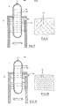
- the expellers 1 shown in FIGS. 1, 7, 9 and 11 are part of a heat pump system. From an absorber 2, which is only hinted at in FIG. 1, a solution enriched with the working fluid of the heat pump, for example iNH 3, is fed through a line 3, which solution is fed into the lower part of the expeller via several rectification trays arranged inside an expeller housing 4 1 arrives. The working fluid is expelled from the solution by heating; it emerges at the upper end of the expeller 1 through a line 5 and is fed to the circuit of the heat pump system. The so-called “poor” solution is passed through a line 6 from the lower part of the expeller 1 via a line 7 back to the absorber 2.
- a solution enriched with the working fluid of the heat pump for example iNH 3
- the working fluid is expelled from the solution by heating; it emerges at the upper end of the expeller 1 through a line 5 and is fed to the circuit of the heat pump system.
- the so-called “poor” solution is passed through a line
- the expeller housing 4 has a long, vertical cylindrical housing section 4a, which is closed at the upper and lower ends by welded-on spherical half-shells 4b and 4c, so that the expeller housing 4 represents a steel container suitable for receiving high internal pressure.
- the major part of the cylindrical housing wall section 4a projects into a heating chamber 8, which is also essentially cylindrical in cross section and in which there is a burner 9 below the expeller 1, which is heated, for example, with gas or heating oil.
- a side heating gas outlet 10 is provided at the upper end of the heating chamber 8.
- cylindrical pins 13 which are butt welded onto the cylindrical housing wall section 4a, in the staggered arrangement of the rows one above the other shown in FIG. Thereby, the hot gases are forced to a continuous change in direction and intense flow around the pin 13 as shown in F ig. 2 is indicated with a drawn line.
- FIG. 3 A modification of this is shown in FIG. 3.
- the pins 14 have circumferential ribs 14a, so that the pin surface is enlarged compared to the cylindrical shape according to FIGS. 1 and 2 in order to improve the heat transfer.
- pins 16 are in one piece with an outer housing wall. 16a of the expeller 1 cast.
- This outer housing wall 16a which consists, for example, of aluminum or an aluminum alloy, is firmly connected to the cylindrical housing wall section 4a forming the inner housing wall of the driver housing 4 welded from steel.
- the pins attached to the cylindrical housing wall section 4a have the shape of narrow, elongated ribs 17 which are inclined with respect to the direction of the generatrix of the cylindrical housing wall section 4a.
- the desired intensive flow around the ribs 17 can be achieved, for example, by uniformly inclining all the ribs 17 in the same direction, as shown in the development according to FIG. 1 0 , or the ribs 17 can alternately one after the other in the rows one above the other Side slanted as shown in Fig. 8.
- the pins around which the heating gases flow are also designed as inclined ribs 18.
- These ribs 18 are teeth of a toothed sheet metal strip 19 which is wound around the cylindrical housing wall section 4a and welded to it.
- the ribs 18 can opposite the Band longitudinal direction inclined, ie be set to take the most favorable direction for the desired flow of the heating gases.
Landscapes
- Engineering & Computer Science (AREA)
- Power Engineering (AREA)
- Physics & Mathematics (AREA)
- Mechanical Engineering (AREA)
- Thermal Sciences (AREA)
- General Engineering & Computer Science (AREA)
- Physical Or Chemical Processes And Apparatus (AREA)
Priority Applications (1)
| Application Number | Priority Date | Filing Date | Title |
|---|---|---|---|
| EP83104514A EP0124632A1 (fr) | 1983-05-07 | 1983-05-07 | Générateur pour pompes à chaleur à sorption |
Applications Claiming Priority (1)
| Application Number | Priority Date | Filing Date | Title |
|---|---|---|---|
| EP83104514A EP0124632A1 (fr) | 1983-05-07 | 1983-05-07 | Générateur pour pompes à chaleur à sorption |
Publications (1)
| Publication Number | Publication Date |
|---|---|
| EP0124632A1 true EP0124632A1 (fr) | 1984-11-14 |
Family
ID=8190452
Family Applications (1)
| Application Number | Title | Priority Date | Filing Date |
|---|---|---|---|
| EP83104514A Withdrawn EP0124632A1 (fr) | 1983-05-07 | 1983-05-07 | Générateur pour pompes à chaleur à sorption |
Country Status (1)
| Country | Link |
|---|---|
| EP (1) | EP0124632A1 (fr) |
Cited By (1)
| Publication number | Priority date | Publication date | Assignee | Title |
|---|---|---|---|---|
| GB2498771A (en) * | 2012-01-27 | 2013-07-31 | Firechill Ltd | A Generator for an Absorption Chiller and an Absorption Chiller Using such a Generator |
Citations (13)
| Publication number | Priority date | Publication date | Assignee | Title |
|---|---|---|---|---|
| GB422823A (en) * | 1934-03-22 | 1935-01-18 | Harold Livsey | Improved construction of sleeve used with tubes of heat exchangers |
| US2584189A (en) * | 1948-10-16 | 1952-02-05 | Svenska Maskinverken Ab | Method of making extended surface heat exchangers |
| GB734169A (en) * | 1952-10-20 | 1955-07-27 | Svenska Maskinverken Ab | Method of and apparatus for generating steam |
| GB906282A (en) * | 1960-10-27 | 1962-09-19 | Birwelco Ltd | Improvements in and relating to heat exchangers |
| US3367310A (en) * | 1966-06-09 | 1968-02-06 | Whirlpool Co | Absorption refrigeration generator |
| US3407625A (en) * | 1966-09-01 | 1968-10-29 | Babcock & Wilcox Co | Vapor generator |
| DE1501500A1 (de) * | 1965-07-20 | 1969-10-30 | David Dalin | Waermeaustauscher |
| FR2012019A1 (fr) * | 1968-07-01 | 1970-03-13 | Carrier Corp | |
| DE2155379A1 (de) * | 1971-11-04 | 1973-05-10 | Trojani Benito | Verbesserte gepfloeckte rohre und herstellungsverfahren derselben |
| DE2251690A1 (de) * | 1972-10-21 | 1974-04-25 | Werner Prof Dr Linke | Rippenanordnung fuer heiz- und kuehlflaechen |
| CH606935A5 (en) * | 1976-05-10 | 1978-11-30 | Heat Res Corp | Gas heater for incinerator |
| EP0001858B1 (fr) * | 1977-10-28 | 1981-04-01 | N.V. Nederlandse Gasunie | Procédé de chauffage et système de chauffage bi-modale pour chauffer des bâtiments |
| DE3143668A1 (de) * | 1981-11-04 | 1983-05-11 | Rekord Heizungs- u. Klimageräte Ruckelshausen GmbH u. Co KG, 6102 Pfungstadt | Austreiber fuer sorptionswaermepumpen |
-
1983
- 1983-05-07 EP EP83104514A patent/EP0124632A1/fr not_active Withdrawn
Patent Citations (13)
| Publication number | Priority date | Publication date | Assignee | Title |
|---|---|---|---|---|
| GB422823A (en) * | 1934-03-22 | 1935-01-18 | Harold Livsey | Improved construction of sleeve used with tubes of heat exchangers |
| US2584189A (en) * | 1948-10-16 | 1952-02-05 | Svenska Maskinverken Ab | Method of making extended surface heat exchangers |
| GB734169A (en) * | 1952-10-20 | 1955-07-27 | Svenska Maskinverken Ab | Method of and apparatus for generating steam |
| GB906282A (en) * | 1960-10-27 | 1962-09-19 | Birwelco Ltd | Improvements in and relating to heat exchangers |
| DE1501500A1 (de) * | 1965-07-20 | 1969-10-30 | David Dalin | Waermeaustauscher |
| US3367310A (en) * | 1966-06-09 | 1968-02-06 | Whirlpool Co | Absorption refrigeration generator |
| US3407625A (en) * | 1966-09-01 | 1968-10-29 | Babcock & Wilcox Co | Vapor generator |
| FR2012019A1 (fr) * | 1968-07-01 | 1970-03-13 | Carrier Corp | |
| DE2155379A1 (de) * | 1971-11-04 | 1973-05-10 | Trojani Benito | Verbesserte gepfloeckte rohre und herstellungsverfahren derselben |
| DE2251690A1 (de) * | 1972-10-21 | 1974-04-25 | Werner Prof Dr Linke | Rippenanordnung fuer heiz- und kuehlflaechen |
| CH606935A5 (en) * | 1976-05-10 | 1978-11-30 | Heat Res Corp | Gas heater for incinerator |
| EP0001858B1 (fr) * | 1977-10-28 | 1981-04-01 | N.V. Nederlandse Gasunie | Procédé de chauffage et système de chauffage bi-modale pour chauffer des bâtiments |
| DE3143668A1 (de) * | 1981-11-04 | 1983-05-11 | Rekord Heizungs- u. Klimageräte Ruckelshausen GmbH u. Co KG, 6102 Pfungstadt | Austreiber fuer sorptionswaermepumpen |
Cited By (2)
| Publication number | Priority date | Publication date | Assignee | Title |
|---|---|---|---|---|
| GB2498771A (en) * | 2012-01-27 | 2013-07-31 | Firechill Ltd | A Generator for an Absorption Chiller and an Absorption Chiller Using such a Generator |
| WO2013110938A3 (fr) * | 2012-01-27 | 2013-10-03 | Firechill Limited | Génératrice pour refroidisseur à absorption et refroidisseur à absorption comprenant une telle génératrice |
Similar Documents
| Publication | Publication Date | Title |
|---|---|---|
| DE2403538C3 (de) | Wärmerohr | |
| DE60209994T2 (de) | Wärmetauscherrohr | |
| DE60310876T2 (de) | Getauchter verdampfer mit integriertem wärmeaustauscher | |
| DE102014005149B4 (de) | Gelöteter Wärmetauscher | |
| DE19543234C2 (de) | Lamellen-Wärmetauscher | |
| EP3301378A1 (fr) | Tuyau de transfert de chaleur et chaudière dotée d'un tel tuyau de transfert de chaleur | |
| DE102004050567A1 (de) | Wärmetauscher | |
| DE3834822A1 (de) | Waermetauscher | |
| EP0681156A1 (fr) | Echangeur de chaleur | |
| DE19515530C2 (de) | Wasserkasten eines Wärmetauschers für Kraftfahrzeuge | |
| DE3014506A1 (de) | Waermeaustauscher mit einem spiralenfoermigen raum fuer den waermeaustausch zwischen wenigstens zwei medien | |
| DE4106296C2 (de) | Wärmetauscher, insbesondere Wasser/Luft-Kühler für Brennkraftmaschinen | |
| DE2450739A1 (de) | Waermeaustauscher, insbesondere oelkuehler | |
| EP0124632A1 (fr) | Générateur pour pompes à chaleur à sorption | |
| EP0386131A1 (fr) | Echangeur de chaleur a contre-courant. | |
| DE2126226C3 (de) | Wärmeaustauscher | |
| DE3143668A1 (de) | Austreiber fuer sorptionswaermepumpen | |
| DE1679396A1 (de) | Heizkessel zum Verfeuern fluessiger oder gasfoermiger Brenstoffe | |
| DE3132078A1 (de) | Waermeaustauscher | |
| EP0026271A2 (fr) | Echangeur de chaleur, en particulier pour chauffe-eau à mazout ou à gaz | |
| DE2224841A1 (de) | Wärmetauscher | |
| DE69801631T2 (de) | Wärmetauscherelement mit hohem Wirkungsgrad für einen Heizkörper in einem Gliederheizkessel | |
| EP1359383A2 (fr) | Echangeur de chaleur | |
| DE627518C (de) | Waermeaustauschvorrichtung fuer Fluessigkeiten, bei der eine Reihe von gewellten Waermeaustauschelementen nebeneinander angeordnet sind | |
| EP0353404B1 (fr) | Refroidisseur d'huile pour moteurs à combustion |
Legal Events
| Date | Code | Title | Description |
|---|---|---|---|
| PUAI | Public reference made under article 153(3) epc to a published international application that has entered the european phase |
Free format text: ORIGINAL CODE: 0009012 |
|
| AK | Designated contracting states |
Designated state(s): AT BE CH DE FR GB IT LI NL SE |
|
| RBV | Designated contracting states (corrected) |
Designated state(s): CH DE FR GB IT LI NL |
|
| 17P | Request for examination filed |
Effective date: 19850508 |
|
| STAA | Information on the status of an ep patent application or granted ep patent |
Free format text: STATUS: THE APPLICATION IS DEEMED TO BE WITHDRAWN |
|
| 18D | Application deemed to be withdrawn |
Effective date: 19860309 |
|
| RIN1 | Information on inventor provided before grant (corrected) |
Inventor name: SCHOTT, EKKEHARD |