EP0125316A1 - Vorrichtung für filmdruck - Google Patents
Vorrichtung für filmdruck Download PDFInfo
- Publication number
- EP0125316A1 EP0125316A1 EP83903570A EP83903570A EP0125316A1 EP 0125316 A1 EP0125316 A1 EP 0125316A1 EP 83903570 A EP83903570 A EP 83903570A EP 83903570 A EP83903570 A EP 83903570A EP 0125316 A1 EP0125316 A1 EP 0125316A1
- Authority
- EP
- European Patent Office
- Prior art keywords
- mounting plate
- mounting
- base frame
- mounting plates
- Prior art date
- Legal status (The legal status is an assumption and is not a legal conclusion. Google has not performed a legal analysis and makes no representation as to the accuracy of the status listed.)
- Withdrawn
Links
Images
Classifications
-
- B—PERFORMING OPERATIONS; TRANSPORTING
- B41—PRINTING; LINING MACHINES; TYPEWRITERS; STAMPS
- B41F—PRINTING MACHINES OR PRESSES
- B41F15/00—Screen printers
- B41F15/14—Details
- B41F15/16—Printing tables
- B41F15/18—Supports for workpieces
-
- B—PERFORMING OPERATIONS; TRANSPORTING
- B41—PRINTING; LINING MACHINES; TYPEWRITERS; STAMPS
- B41F—PRINTING MACHINES OR PRESSES
- B41F15/00—Screen printers
- B41F15/08—Machines
- B41F15/0863—Machines with a plurality of flat screens mounted on a turntable
Definitions
- This invention relates to a screen printing apparatus for screenprinting of print materials having air-permeability such as T-shirts, clothing bags, clothing pieces, Japanese papers, felt materials etc. and simultaneously for drying them while the print materials are held on mounting plates.
- mounting plates of the above screen printing apparatus are made of plywood boards, aluminium plates, or stainless steel plates. Such mounting plates, however, have the following defects.
- This invention relates to a screen printing apparatus in which a plurality of mounting plates, each of which can replaceably mount a print material thereon, are mounted on a base frame such that the mounting plates can move around the base frame in an endless manner and intermittently, that at least one drying device is disposed along a moving locus of the mounting plate, and that the mounting plate is made of the air-permeable material.
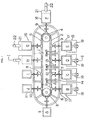
- Fig. 1 is a plan view of the screen printing apparatus of the present invention
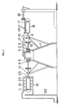
- Fig. 2 is a cross sectional view taken along the line I - I of Fig. 1
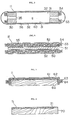
- Fig. 3 to Fig. 6 are transverse sectional views of the mounting plate.
- Fig. 1 and Fig. 2 show the entire construction of the screen printing apparatus of the present invention.
- numeral (1) is a base frame having an elongated square'frame construction.
- the base frame (1) is provided with sprocket wheels (3), (4) which are rotatable by a motor (not shown in the drawing) on both ends thereof for mounting an endless chain (2) around the base frame (1).
- the base frame (1) also comprises an endless-chain guide rail (5) at the upper portion thereof and an elongated circular mounting-shaft guide rail (6) which encircles the outer circumference of the endless-chain guide rail (5) with a desired space.
- a plurality of mounting shaft (7) are connected to the endless chain (2) at a predetermined interval by means of an attachment (8) and a bearing (9).
- Each mounting shaft (7) has a roller (10) in the midst thereof which rolls on the guide rail (6) and is provided with a mounting plate (11) at the distal end thereof.
- This construction makes it possible that the intermittent drive of the sprocket wheel (3) rotates the endless chain (2) intermittently around the base frame (1) and therefore a group of mounting plates (11) also rotate intermittently around the base frame (1) by the rotation of the endless chain (2).
- the base frame (1) has a mounting-plate revolving mechanism.
- this mounting-plate revolving mechanism is constructed by fixing a pinion (12) at a place between the bearing (9) and the roller (10) and pivotally engaging the pinion (12) with a rack (14) attached on the end of a tilt arm (13) on the top of the base frame (1).
- a printing device (15) and a drying device (16) are disposed around the periphery of the base frame (1) at desired space and at the mounting-plate stop position.
- the printing device (15) comprises a print screen (17) disposed on the moving locus of the mounting plate (1) and a support arm (18) supporting the print screen (17) tiltably.
- Numeral (19) is a squeeze.
- a plurality of drying devices (16) are also arranged similarly on the moving locus of the mounting plate (11) and each drying device (16) comprises a heating booth (21) having an infrared heater (20) therein and an exhaust duct (22) which communicates with the heating booth (21).
- Numeral (23) is an elongated slit formed on the inner side of the heating booth (21) and is provided for assuring the smooth movement of the mounting shaft (7).
- Fig. 3 to Fig. 6 show the construction of the mounting plate (11) which characterizes the present invention.
- the mounting plate (11) is constructed such that a stainless net (31) (preferably 100 - 300 meshes (inches)) is mounted on both upper and lower sides of an aluminum frame (30) forming a space (a) therebetween and a cover clothing (32) having air-permeability is attached on the stainless net (31) by means of a tightening frame (33) and a heat-resistant rubber (34).
- Numeral (35) is an exhaust opening formed on the aluminum frame (30) and this is not necessarily required.
- Numeral (36) is a temporary adhering agent used in setting the print materials (40).
- the mounting plate (11) is constructed such that open porous bodies (52) such as porous ceramic plates are mounted on the both sides of an aluminum support member (50) by means of adhering layers (51) and a cotton textile (55) is removably mounted on the surface of the open porous bodies (52) by means of tightening frames (53) and heat-resistant rubbers (54).
- open porous bodies (52) such as porous ceramic plates are mounted on the both sides of an aluminum support member (50) by means of adhering layers (51) and a cotton textile (55) is removably mounted on the surface of the open porous bodies (52) by means of tightening frames (53) and heat-resistant rubbers (54).
- the mounting plate (11) is constructed such that an open porous body (61) and a cotton textile (62) are mounted only one side of a support member (60) made of plywood board, while in Fig. 6, the mounting plate (11) is constructed by mounting only an open porous body (71) on the support member (70) made of plywood board.
- numeral (63) is a tightening frame and numeral (64) is a heat-resistant rubber.
- the operation of the print screen apparatus having the above mounting plate (11) is explained in view of Fig. 1.
- the print material (40) (for example, T-shirt) is set on the mounting plate (11) at a position A.
- the mounting plate (11) is moved to a position B along with the rotation of the endless chain (2) and a first pattern is printed on the surface of the print material (40).
- the rack (14) engages with the pinion (12) during the movement between a position C and a position D and the print material (40) is reversed 180 degrees together with the mounting plate (11).
- Third and fourth patterns are printed at a position D and a position E.
- the mounting plate (11) has substantially the air-permeability, the ink does not make the mounting plate (11) dirty and the print screen (17) is not clogged.
- the mounting plate (11) After completing the printing operation, the mounting plate (11) is dried successively at a position F, a position G, and a position H, and then is moved to a position I and a position J.
- the print material (40) is removed from the mounting plate (11) at the position J as the final product.
- the present invention that has the construction and operation as mentioned above can have the following advantages.
Landscapes
- Engineering & Computer Science (AREA)
- Mechanical Engineering (AREA)
- Screen Printers (AREA)
- Coloring (AREA)
Applications Claiming Priority (2)
| Application Number | Priority Date | Filing Date | Title |
|---|---|---|---|
| JP19950782A JPS5989155A (ja) | 1982-11-12 | 1982-11-12 | スクリ−ン印刷装置 |
| JP199507/82 | 1982-11-12 |
Publications (2)
| Publication Number | Publication Date |
|---|---|
| EP0125316A1 true EP0125316A1 (de) | 1984-11-21 |
| EP0125316A4 EP0125316A4 (de) | 1985-06-26 |
Family
ID=16408963
Family Applications (1)
| Application Number | Title | Priority Date | Filing Date |
|---|---|---|---|
| EP19830903570 Withdrawn EP0125316A4 (de) | 1982-11-12 | 1983-11-11 | Vorrichtung für filmdruck. |
Country Status (3)
| Country | Link |
|---|---|
| EP (1) | EP0125316A4 (de) |
| JP (1) | JPS5989155A (de) |
| WO (1) | WO1984001921A1 (de) |
Cited By (3)
| Publication number | Priority date | Publication date | Assignee | Title |
|---|---|---|---|---|
| FR2752771A1 (fr) * | 1996-08-27 | 1998-03-06 | Dome Laurent | Double jeannette adaptable sur tout type de machine circulaire de serigraphie |
| WO2001025011A1 (en) * | 1999-10-05 | 2001-04-12 | M & R Printing Equipment, Inc. | Method and apparatus for the automatic loading of a article onto a printing machine |
| CN102582226A (zh) * | 2012-02-28 | 2012-07-18 | 武汉纺织大学 | 自动丝网印花机的传动装置 |
Families Citing this family (8)
| Publication number | Priority date | Publication date | Assignee | Title |
|---|---|---|---|---|
| JPS6268751A (ja) * | 1985-09-20 | 1987-03-28 | Yamato Amimono Kk | ストツキング類の捺染方法 |
| JPS6297844A (ja) * | 1985-10-24 | 1987-05-07 | Toshin Kogyo Kk | 伸縮性編成衣料への捺染方法 |
| JPS62146629A (ja) * | 1985-12-20 | 1987-06-30 | Taihei Kogyo Kk | ブロ−転写装置 |
| JPS62187037A (ja) * | 1986-02-13 | 1987-08-15 | Ashida Seisakusho:Kk | 靴下の滑り止め処理加工装置 |
| JPH01190454A (ja) * | 1988-01-25 | 1989-07-31 | Nippon Kiyokumen Insatsu Kenkyusho:Kk | 多色印刷装置および被加工物の位置決め装置 |
| CN105690984B (zh) * | 2016-04-08 | 2019-03-08 | 石狮市七彩虹植绒印花有限公司 | 一种自动印花装置 |
| CN105690981B (zh) * | 2016-04-08 | 2019-03-08 | 石狮市七彩虹植绒印花有限公司 | 一种全自动高效印花机 |
| CN114055915B (zh) * | 2021-11-11 | 2022-11-29 | 宁夏青林华源科技有限公司 | 一种环保手提袋生产用染色印图装置 |
Family Cites Families (11)
| Publication number | Priority date | Publication date | Assignee | Title |
|---|---|---|---|---|
| FR718925A (fr) * | 1930-08-15 | 1932-01-30 | Procédé d'impression, poncage, etc., de tricots, dentelles et autres matières délicates | |
| FR1018727A (fr) * | 1950-05-23 | 1953-01-12 | Nouveau procédé d'impression de tissus extensibles ou élastiques | |
| JPS51123384A (en) * | 1975-04-21 | 1976-10-28 | Naado Kenkiyuushiyo Kk | Printing method of socks |
| JPS51149986A (en) * | 1975-06-19 | 1976-12-23 | Naado Kenkiyuushiyo Kk | Printing method of socks |
| JPS5240688A (en) * | 1975-09-27 | 1977-03-29 | Naado Kenkiyuushiyo Kk | Method of printing socks |
| DE2637721C2 (de) * | 1976-08-21 | 1983-07-07 | Mathias 4815 Schloss Holte Mitter | Einrichtung zum Führen von Warenbahnen in einer Ebene |
| DE2643226C2 (de) * | 1976-09-25 | 1982-07-29 | Mathias 4815 Schloss Holte Mitter | Vorrichtung zum absatzweisen Bedrucken von Druckgut, insbesondere Warenbahnen mittels mehrerer bewegbarer ebener Schablonen |
| DE2834464A1 (de) * | 1977-08-11 | 1979-02-22 | Mathias Mitter | Einrichtung zur fuehrung einer warenbahn, insbesondere einer florware ueber einer druck- oder faerbestation |
| JPS55111261A (en) * | 1979-02-20 | 1980-08-27 | Toshin Kogyo Kk | Method and device for printing thick cloth having pile or raising |
| JPS5912195Y2 (ja) * | 1980-02-06 | 1984-04-13 | 有限会社琉球スクリ−ン印刷 | Tシャツプリント装置 |
| JPS57125334A (en) * | 1981-01-28 | 1982-08-04 | Mitsubishi Electric Corp | Temperature sensor for electric appliance |
-
1982
- 1982-11-12 JP JP19950782A patent/JPS5989155A/ja active Pending
-
1983
- 1983-11-11 EP EP19830903570 patent/EP0125316A4/de not_active Withdrawn
- 1983-11-11 WO PCT/JP1983/000406 patent/WO1984001921A1/ja not_active Ceased
Cited By (5)
| Publication number | Priority date | Publication date | Assignee | Title |
|---|---|---|---|---|
| FR2752771A1 (fr) * | 1996-08-27 | 1998-03-06 | Dome Laurent | Double jeannette adaptable sur tout type de machine circulaire de serigraphie |
| WO2001025011A1 (en) * | 1999-10-05 | 2001-04-12 | M & R Printing Equipment, Inc. | Method and apparatus for the automatic loading of a article onto a printing machine |
| US6439370B1 (en) | 1999-10-05 | 2002-08-27 | M&R Printing Equipment, Inc. | Method and apparatus for the automatic loading of an article onto a printing machine |
| CN102582226A (zh) * | 2012-02-28 | 2012-07-18 | 武汉纺织大学 | 自动丝网印花机的传动装置 |
| CN102582226B (zh) * | 2012-02-28 | 2014-05-28 | 武汉纺织大学 | 自动丝网印花机的传动装置 |
Also Published As
| Publication number | Publication date |
|---|---|
| WO1984001921A1 (fr) | 1984-05-24 |
| EP0125316A4 (de) | 1985-06-26 |
| JPS5989155A (ja) | 1984-05-23 |
Similar Documents
| Publication | Publication Date | Title |
|---|---|---|
| EP0125316A1 (de) | Vorrichtung für filmdruck | |
| US6526884B1 (en) | Detachable inking device for a flexographic printing machine, its embodiment, cleaning and use in such a machine | |
| JP2511861B2 (ja) | 回転スクリ−ン印刷装置 | |
| JPH05237426A (ja) | 接着剤塗付装置 | |
| SK16395A3 (en) | Rotary printing machine | |
| CN1321007C (zh) | 用于印刷物体的方法和装置 | |
| JP3363925B2 (ja) | 印刷用スクリーンの清掃方法及び装置 | |
| JPS606463A (ja) | 連続多色印刷方法及び装置 | |
| AU583842B2 (en) | Screen printing apparatus and process | |
| JP2902418B2 (ja) | スクリーン印刷機のクリーニング装置 | |
| CN110303766A (zh) | 一种印刷机橡皮布自动清洗装置 | |
| JPH04119324A (ja) | 液晶パネル製造装置 | |
| CN211463693U (zh) | 一种板材印刷用油墨喷涂装置 | |
| KR100270242B1 (ko) | 스크린식인쇄도포장치및도포막의건조방법 | |
| JPH02260Y2 (de) | ||
| CN115555180B (zh) | 基于负压吸附作用的纺织自动化印染装置 | |
| CN221737449U (zh) | 一种剪纸图样印刷用滚筒 | |
| JP3737857B2 (ja) | パウダー付着方法と装置 | |
| JPH0349293A (ja) | 配線基板用印刷装置 | |
| JPS6142843Y2 (de) | ||
| SU1740197A1 (ru) | Способ нанесени двухстороннего офсетного изображени и печатный аппарат дл его осуществлени | |
| JPS6063164A (ja) | 印刷機における乾燥装置 | |
| JPH0538937Y2 (de) | ||
| JPS635917B2 (de) | ||
| JPS6226200Y2 (de) |
Legal Events
| Date | Code | Title | Description |
|---|---|---|---|
| PUAI | Public reference made under article 153(3) epc to a published international application that has entered the european phase |
Free format text: ORIGINAL CODE: 0009012 |
|
| 17P | Request for examination filed |
Effective date: 19840710 |
|
| AK | Designated contracting states |
Designated state(s): DE FR GB NL SE |
|
| STAA | Information on the status of an ep patent application or granted ep patent |
Free format text: STATUS: THE APPLICATION IS DEEMED TO BE WITHDRAWN |
|
| 18D | Application deemed to be withdrawn |
Effective date: 19860602 |
|
| RIN1 | Information on inventor provided before grant (corrected) |
Inventor name: YARA, CHOSUKE |