EP0125341A1 - Dispositif et procédé pour le nettoyage d'une machine de filature à fibres libérées par friction - Google Patents
Dispositif et procédé pour le nettoyage d'une machine de filature à fibres libérées par friction Download PDFInfo
- Publication number
- EP0125341A1 EP0125341A1 EP83111845A EP83111845A EP0125341A1 EP 0125341 A1 EP0125341 A1 EP 0125341A1 EP 83111845 A EP83111845 A EP 83111845A EP 83111845 A EP83111845 A EP 83111845A EP 0125341 A1 EP0125341 A1 EP 0125341A1
- Authority
- EP
- European Patent Office
- Prior art keywords
- formation area
- yarn
- slot
- yarn formation
- sleeve
- Prior art date
- Legal status (The legal status is an assumption and is not a legal conclusion. Google has not performed a legal analysis and makes no representation as to the accuracy of the status listed.)
- Granted
Links
- 238000004140 cleaning Methods 0.000 title claims description 11
- 238000000034 method Methods 0.000 title claims description 10
- 238000007383 open-end spinning Methods 0.000 title claims description 10
- 230000015572 biosynthetic process Effects 0.000 claims abstract description 37
- 239000000835 fiber Substances 0.000 claims description 26
- 238000009987 spinning Methods 0.000 claims description 12
- 238000010040 friction spinning Methods 0.000 abstract description 3
- 239000000463 material Substances 0.000 description 5
- 238000004519 manufacturing process Methods 0.000 description 2
- 239000002184 metal Substances 0.000 description 2
- 230000002093 peripheral effect Effects 0.000 description 2
- 239000003795 chemical substances by application Substances 0.000 description 1
- 239000007787 solid Substances 0.000 description 1
Images
Classifications
-
- D—TEXTILES; PAPER
- D01—NATURAL OR MAN-MADE THREADS OR FIBRES; SPINNING
- D01H—SPINNING OR TWISTING
- D01H4/00—Open-end spinning machines or arrangements for imparting twist to independently moving fibres separated from slivers; Piecing arrangements therefor; Covering endless core threads with fibres by open-end spinning techniques
- D01H4/04—Open-end spinning machines or arrangements for imparting twist to independently moving fibres separated from slivers; Piecing arrangements therefor; Covering endless core threads with fibres by open-end spinning techniques imparting twist by contact of fibres with a running surface
- D01H4/22—Cleaning of running surfaces
- D01H4/26—Cleaning of running surfaces in friction spinning
-
- D—TEXTILES; PAPER
- D01—NATURAL OR MAN-MADE THREADS OR FIBRES; SPINNING
- D01H—SPINNING OR TWISTING
- D01H4/00—Open-end spinning machines or arrangements for imparting twist to independently moving fibres separated from slivers; Piecing arrangements therefor; Covering endless core threads with fibres by open-end spinning techniques
- D01H4/48—Piecing arrangements; Control therefor
- D01H4/52—Piecing arrangements; Control therefor for friction spinning
Definitions
- This invention relates to apparatus for the open-end spinning of yarn and particularly to apparatus of the kind known as friction spinning.
- the invention relates to the removal of a fibre mass from such an apparatus in the event of a yarn break.
- Apparatus of this kind is disclosed in our published British Patent No. 2,042,599 and comprises two bodies of rotation each defining a surface and arranged such that the surfaces are closely adjacent at a line of closest approach so as to define between them at that line a yarn formation area, a fibre feed duct for feeding an airborne stream of fibres into the yarn formation area which feed duct terminates closely adjacent the surfaces, means for rotating each of the bodies about a respective axis so as to twist the fibres in the area into a yarn, and means for withdrawing the yarn from the 'area.
- patent 4,168,601 discloses an arrangement which also does not have the necessary small gaps and tolerances; but in this arrangement an inner cylindrical roller can be moved axially away from co-operation with the inner surface of an outer roller to allow cleaning of any material remaining in the spinning area at a stoppage and to perform the piecing up function.
- the spinning area is very large in comparison with the diameter of a yarn and hence there is no need for consideration of problems concerning excess material in that area during operation.
- the provisions for cleaning this form of apparatus would therefore be adequate to allow proper cleaning of the area although the structure is extremely cumbersome and therefore time consuming and also expensive to manufacture. It is also necessary to stop the motion of the surfaces.
- the invention provides a further method of cleaning following a yarn break an apparatus for open-end spinning of yarn comprising a body having a perforated surface, means defining an elongate yarn formation area on the surface, suction means for developing an air stream through the surface at the yarn formation area, and a fibre feed duct for feeding fibres on to the yarn formation area, the method being characterized in that the airstream through the surface is gradually closed off from one end of the area toward the opposite end whereby to move any fibres remaining on the area toward the opposite end for ejection from the area.
- the present invention provides apparatus for open end spinning of yarn, comprising a body having a perforated surface, means defining an elongate yarn formation area on the surface, suction means for developing an airstream through the surface at the yarn formation area, and a fibre feed duct for feeding fibres onto the yarn formation area, characterized by means for closing off the airstream through the surface progressively starting from one end of the yarn formation are and ending at the other end.
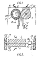
- the apparatus comprises a pair of cylindrical rollers 1 and 2 rotating in the direction shown by the arrows and arranged closely adjacent at a line of closest approach.
- the roller 1 is imperforate and comprises a solid metal roller.
- the roller 2 is perforated over the majority of its peripheral surface and has a sleeve 6 defining a suction duct closely adjacent the inside surface with an elongate suction slot 7 which extends substantially fully along the roller 1 at or adjacent the line of closest approach.
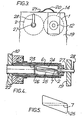
- FIG 4 the mounting and bearing arrangements are substantially as shown and fully described in our published British Patent 2,042,599, as is the sleeve 6.
- a duct 22 communicates suction from a suction source (not shown) with the sleeve 6 and _ terminates at an end collar 23 adjacent the perforated portion of the roller 2.
- An inner sleeve 24 coaxial with the roller 2 and sleeve 6 is arranged to have its peripheral surface closely adjacent the inner surface of the sleeve 6 to prevent leakages of air and has a slot 25 having the shape of a parallelogram as shown in Figure 5, which is a development view of the sleeve 24. The purpose of the slot 25 will be explained hereinafter.
- the slot 25 has one pair of opposite edges (opposite sides of the parallelogram) oblique to the rectilinear edges of the suction slot 7, which is parallel to a generatrix of the sleeve 6,and its other edges perpendicular to the slot 7 (i.e. perpendicular to a generatrix of the sleeve 24).
- the sleeve 24 terminates at one end in a collar 26, for co-operation with the collar 23 to allow rotation of the sleeve 24 but to prevent axial movement, and at the other end in a shaft 27 which extends through a bore in the end of the sleeve 6 and which carries a manually operable lever 28 whereby the sleeve 24 can be rotated inside the sleeve 6.
- a fibre feed duct 8 is fixedly mounted on a portion of machine frame-work 9 shown only schematically; the details of the fibre feed duct 8 are more fully described in our published British Patent Application No. 2,094,843. It suffices to say here that the gaps between the rollers and between the rollers 1 and 2 and the fibre feed duct 8 are kept small and the fibre feed duct 8 projects well in between the rollers 1 and 2 toward the line of closest approach so that a small confined zone or yarn formation area is formed.
- fibres are fed from the fibre feed duct 8 and are twisted into yarn by the rotating of the rollers 1 and 2 as disclosed in detail in our published British Patent No. 2,042,599.
- the roller 2 is mounted via the suction duct/sleeve 6 on a machine frame member 10 substantially as shown in Figure 1 of our published British Patent No. 2,042,599 such that it is rigidly supported by the member 10 which in turn is rigidly connected to the frame member 9.
- the fibre feed duct 8 and roller 2 are fixed in relation to one another.
- the roller 1 is mounted on a shaft 11 carried in bearings 12, 13 in turn supported in metal support plates 14, 15 such that the roller 1 is free to rotate in the plates 14, 15 but is rigidly supported thereby.
- the shaft carries a drive pulley 16 co-operating with a belt 17 which drives the roller and also drives the roller 2 by means not shown.
- the plate 15 is a close fit within an opening cut in the frame member 10 and is carried on a pivot 18 rigidly fixed thereto.
- the plate 14 is similarly a close sliding fit within an opening in a further frame member 19 so that when in position in the frame member 19 it locates the roller 1 accurately relative to the fibre feed duct 8 and the roller 2, in accordance with settings applied previously or during manufacture.
- a leaf spring 2 0 fixed to the frame member 19 by a screw 21 applies spring bias to the plate 14 so as to maintain it in its position in the frame member 19.
- the spring is designed to apply only sufficient force to counteract the turning moment generated by pressure from the belt 17.
- the plate 14 In use, under normal spinning conditions, the plate 14 remains in position in the frame member 19 and hence the settings between the rollers 1 and 2 and the fibre feed duct 8 are maintained. However on an end break or any other fault occurring whereby an excessive amount of fibres enters the confined space defining the yarn formation area, the pressure developed by the excess fibres tends to lift the roller 1 away from the feed duct by pivoting movement about the pivot 18 thus avoiding excessive force on the rollers and feed duct and possible resultant damage.
- the axis of the pivot 18 lies in a plane parallel to one containing the axes of the rollers 1 and 2 and hence movement of the roller 1 is perpendicular to that plane.
- roller 2 tends to move any excess material away from the fibre feed duct 8 whereas the roller 1 tends to move it into the narrow gap between the fibre feed duct 8 and the roller 1.
- movement only of the roller 1 is sufficient to prevent excess material causing damage.
- movement only of the roller 1 is more simply achieved because it does not have the complexity of mounting and suction connections necessary for the roller 2 (as shown in Figure 4).
- motion of both of the rollers in this direction could be provided preferably by a pivoting arrangement.
- the lever 28 is manually turned anticlockwise to rotate the inner sleeve 24 in the same direction.
- This causes the lower oblique edge of the slot 25 to move upwardly to gradually close off the slot 7 from the end at the back of the unit adjacent the drive belt 17 forwardly to the front end of the slot so that the remaining elongate mass of fibres is drawn forwards by the remaining airflow through the open part of the slot 7 along the slot and eventually ejected from the spinning area after the slot 7 is fully closed.
- the mass falls from the spinning area through the space left between the fibre feed duct 8 and the roller 1 after it has been lifted and can be caught beneath the spinning unit on a catch-tray (not shown) for later cleaning.
- the closing off of the slot 7 is carried out gradually from the back to carry the fibre mass away from the influence of the fibre-orienting suction applied to the fibre feed duct 8 (not shown in these drawings but disclosed in our published British Patent No. 2,042,599) and to assist in causing one end of the fibre mass to fall from the fibre feed duct 8 thus releasing the whole of the mass.
- the lever 28 can be moved also in a clockwise direction so that the upper surface of the slot 25 acts to close off the slot 7 from the front toward the back.
Landscapes
- Engineering & Computer Science (AREA)
- Mechanical Engineering (AREA)
- Textile Engineering (AREA)
- Spinning Or Twisting Of Yarns (AREA)
Applications Claiming Priority (2)
| Application Number | Priority Date | Filing Date | Title |
|---|---|---|---|
| GB8032418 | 1980-10-08 | ||
| GB8032418 | 1980-10-08 |
Related Parent Applications (1)
| Application Number | Title | Priority Date | Filing Date |
|---|---|---|---|
| EP81303762.9 Division | 1981-08-18 |
Publications (2)
| Publication Number | Publication Date |
|---|---|
| EP0125341A1 true EP0125341A1 (fr) | 1984-11-21 |
| EP0125341B1 EP0125341B1 (fr) | 1986-12-17 |
Family
ID=10516551
Family Applications (2)
| Application Number | Title | Priority Date | Filing Date |
|---|---|---|---|
| EP83111845A Expired EP0125341B1 (fr) | 1980-10-08 | 1981-08-18 | Dispositif et procédé pour le nettoyage d'une machine de filature à fibres libérées par friction |
| EP81303762A Expired EP0052412B2 (fr) | 1980-10-08 | 1981-08-18 | Procédé et dispositif de filage de fil par friction suivant le principe open-end |
Family Applications After (1)
| Application Number | Title | Priority Date | Filing Date |
|---|---|---|---|
| EP81303762A Expired EP0052412B2 (fr) | 1980-10-08 | 1981-08-18 | Procédé et dispositif de filage de fil par friction suivant le principe open-end |
Country Status (4)
| Country | Link |
|---|---|
| US (1) | US4380892A (fr) |
| EP (2) | EP0125341B1 (fr) |
| JP (2) | JPS6024849B2 (fr) |
| DE (1) | DE3168150D1 (fr) |
Cited By (2)
| Publication number | Priority date | Publication date | Assignee | Title |
|---|---|---|---|---|
| WO1987000214A1 (fr) * | 1985-06-24 | 1987-01-15 | Schubert & Salzer Maschinenfabrik Aktiengesellscha | Procede et dispositif pour relier les fils sur une installation de filage open-end a friction |
| EP0210393A1 (fr) * | 1985-07-30 | 1987-02-04 | Schubert & Salzer Maschinenfabrik Aktiengesellschaft | Procédé et dispositif de filature de fibres libérées à friction |
Families Citing this family (36)
| Publication number | Priority date | Publication date | Assignee | Title |
|---|---|---|---|---|
| AT381731B (de) * | 1982-12-10 | 1986-11-25 | Fehrer Ernst | Verfahren und vorrichtung zum herstellen eines garnes aus einer verstreckten faserlunte |
| ATE14758T1 (de) * | 1982-05-21 | 1985-08-15 | Hollingsworth Uk Ltd | Einrichtung zur herstellung eines zusammengesetzten garnes durch friktionsspinnen. |
| DE3305621A1 (de) * | 1983-02-18 | 1984-08-23 | Fritz 7347 Bad Überkingen Stahlecker | Oe-friktionsspinnmaschine |
| DE3306225A1 (de) * | 1983-02-23 | 1984-08-23 | Fritz 7347 Bad Überkingen Stahlecker | Vorrichtung zum oe-friktionsspinnen |
| DE3308248A1 (de) * | 1983-03-09 | 1984-09-13 | Fritz 7347 Bad Überkingen Stahlecker | Oe-friktionsspinnmaschine |
| DE3308247A1 (de) * | 1983-03-09 | 1984-09-13 | Fritz 7347 Bad Überkingen Stahlecker | Oe-friktionsspinnmaschine |
| DE3316656A1 (de) * | 1983-05-06 | 1984-11-08 | Fritz 7347 Bad Überkingen Stahlecker | Vorrichtung zum oe-friktionsspinnen |
| DE3464066D1 (en) * | 1983-06-15 | 1987-07-09 | Hollingsworth Uk Ltd | Friction open-end spinning apparatus |
| DE3325928A1 (de) * | 1983-07-19 | 1985-01-31 | Fritz 7347 Bad Überkingen Stahlecker | Verfahren und vorrichtung zum anspinnen eines garnes an einem spinnaggregat einer oe-friktionsspinnmaschine |
| DE3331195A1 (de) * | 1983-08-30 | 1985-03-14 | Fritz 7347 Bad Überkingen Stahlecker | Vorrichtung zum oe-friktionsspinnen |
| DE3333051A1 (de) * | 1983-09-14 | 1985-03-28 | Fritz 7347 Bad Überkingen Stahlecker | Maschine zum oe-friktionsspinnen |
| DE3335065A1 (de) * | 1983-09-28 | 1985-04-04 | Stahlecker, Fritz, 7347 Bad Überkingen | Vorrichtung zum oe-friktionsspinnen |
| DE3336547A1 (de) * | 1983-10-07 | 1985-04-18 | Fritz 7347 Bad Überkingen Stahlecker | Vorrichtung zum oe-friktionsspinnen |
| DE3338834A1 (de) * | 1983-10-26 | 1985-05-09 | Fritz 7347 Bad Überkingen Stahlecker | Oe-friktionsspinnmaschine |
| DE3339129A1 (de) * | 1983-10-28 | 1985-05-09 | Fritz 7347 Bad Überkingen Stahlecker | Verfahren und vorrichtung zum reinigen eines spinnaggregates einer oe-friktionsspinnmaschine |
| DE3342481A1 (de) * | 1983-11-24 | 1985-06-05 | Fritz 7347 Bad Überkingen Stahlecker | Oe-friktionsspinnmaschine |
| DE3343483A1 (de) * | 1983-12-01 | 1985-06-13 | Fritz 7347 Bad Überkingen Stahlecker | Oe-friktionsspinnmaschine |
| DE3343762A1 (de) * | 1983-12-03 | 1985-06-13 | Fritz 7347 Bad Überkingen Stahlecker | Oe-friktionsspinnmaschine |
| DE3401316A1 (de) * | 1984-01-17 | 1985-07-18 | Fritz 7347 Bad Überkingen Stahlecker | Verfahren zum stillsetzen und wiederanfahren eines oe-friktionsspinnaggregates |
| AT383377B (de) * | 1984-01-19 | 1987-06-25 | Fehrer Textilmasch | Verfahren zum anspinnen eines garnes bei einer friktionsspinnvorrichtung |
| DE3410471A1 (de) * | 1984-03-22 | 1985-09-26 | Fritz 7347 Bad Überkingen Stahlecker | Oe-friktionsspinnmaschine mit einer vielzahl von spinnaggregaten und einem verfahrbaren wartungsgeraet |
| DE3417308A1 (de) * | 1984-05-10 | 1985-11-21 | W. Schlafhorst & Co, 4050 Mönchengladbach | Verfahren und vorrichtung zum fadenansetzen bei friktionsspinnmaschinen |
| US4590756A (en) * | 1984-08-10 | 1986-05-27 | Hans Stahlecker | Open-end friction spinning |
| DE3432622A1 (de) * | 1984-09-05 | 1986-03-13 | Fritz 7347 Bad Überkingen Stahlecker | Vorrichtung zum oe-friktionsspinnen |
| GB2165269B (en) * | 1984-10-03 | 1987-07-29 | Hollingsworth | Friction spinning apparatus |
| GB2166164B (en) * | 1984-10-26 | 1988-05-25 | Hollingsworth Uk Ltd | Open-end spinning apparatus |
| GB2166165B (en) * | 1984-10-29 | 1987-07-08 | Hollingsworth | Friction spinning apparatus |
| DE3441493A1 (de) * | 1984-11-13 | 1986-05-15 | Schubert & Salzer Maschinenfabrik Ag, 8070 Ingolstadt | Offenend-spinnvorrichtung |
| DE3443901A1 (de) * | 1984-12-01 | 1986-06-05 | Fritz 7347 Bad Überkingen Stahlecker | Vorrichtung zum oe-friktionsspinnen |
| GB2168390B (en) * | 1984-12-18 | 1988-02-03 | Hollingsworth Uk Ltd | Friction spinning apparatus |
| DE3506254A1 (de) * | 1985-02-22 | 1986-08-28 | W. Schlafhorst & Co, 4050 Mönchengladbach | Spinnvorrichtung zum herstellen eines gedrehten fadens |
| DE3533587A1 (de) * | 1985-09-20 | 1987-04-16 | Schubert & Salzer Maschinen | Verfahren und vorrichtung zum wiederanspinnen einer offenend-friktionsspinnvorrichtung |
| JPH0291452A (ja) * | 1988-09-28 | 1990-03-30 | Hino Motors Ltd | 2ピースピストン |
| DE19608829A1 (de) * | 1996-03-07 | 1997-09-18 | Fritz Stahlecker | Saugwalze für Offenend-Spinnmaschinen |
| KR100839314B1 (ko) | 2002-04-11 | 2008-06-17 | 아크조 노벨 엔.브이. | 오염 방지제의 도포 방법 |
| CN107446575B (zh) | 2016-05-30 | 2021-08-31 | 日亚化学工业株式会社 | β赛隆荧光体的制造方法 |
Citations (3)
| Publication number | Priority date | Publication date | Assignee | Title |
|---|---|---|---|---|
| FR2339687A1 (fr) * | 1976-02-02 | 1977-08-26 | Fehrer Textilmasch | Appareil a filer les fibres textiles |
| AT339778B (de) * | 1976-03-22 | 1977-11-10 | Fehrer Ernst Gmbh | Vorrichtung zum spinnen textiler fasern |
| EP0034427A1 (fr) * | 1980-02-16 | 1981-08-26 | Hollingsworth (U.K.) Limited | Dispositif et procédé de filature à bout libéré |
Family Cites Families (4)
| Publication number | Priority date | Publication date | Assignee | Title |
|---|---|---|---|---|
| FR2383253A1 (fr) * | 1977-03-09 | 1978-10-06 | Vyzk Ustav Bavlnarsky | Procede et dispositif de filage de fil par friction suivant le principe open-end |
| ATA170978A (de) * | 1977-03-30 | 1990-09-15 | Schlafhorst & Co W | Verfahren und vorrichtung zum spinnen eines fadens aus einzelfasern |
| JPS5493127A (en) * | 1977-12-28 | 1979-07-24 | Kogyo Gijutsuin | Adjusting of yarn splicing in absorbing and twisting fine spinning frame |
| GB2042599B (en) * | 1978-10-26 | 1983-09-21 | Platt Saco Lowell Ltd | Open-end spinning apparatus |
-
1981
- 1981-08-18 EP EP83111845A patent/EP0125341B1/fr not_active Expired
- 1981-08-18 EP EP81303762A patent/EP0052412B2/fr not_active Expired
- 1981-08-18 DE DE8181303762T patent/DE3168150D1/de not_active Expired
- 1981-08-26 JP JP56133937A patent/JPS6024849B2/ja not_active Expired
- 1981-09-14 US US06/301,917 patent/US4380892A/en not_active Expired - Lifetime
-
1984
- 1984-11-07 JP JP59234855A patent/JPS60126332A/ja active Granted
Patent Citations (3)
| Publication number | Priority date | Publication date | Assignee | Title |
|---|---|---|---|---|
| FR2339687A1 (fr) * | 1976-02-02 | 1977-08-26 | Fehrer Textilmasch | Appareil a filer les fibres textiles |
| AT339778B (de) * | 1976-03-22 | 1977-11-10 | Fehrer Ernst Gmbh | Vorrichtung zum spinnen textiler fasern |
| EP0034427A1 (fr) * | 1980-02-16 | 1981-08-26 | Hollingsworth (U.K.) Limited | Dispositif et procédé de filature à bout libéré |
Cited By (3)
| Publication number | Priority date | Publication date | Assignee | Title |
|---|---|---|---|---|
| WO1987000214A1 (fr) * | 1985-06-24 | 1987-01-15 | Schubert & Salzer Maschinenfabrik Aktiengesellscha | Procede et dispositif pour relier les fils sur une installation de filage open-end a friction |
| US4817380A (en) * | 1985-06-24 | 1989-04-04 | Schubert & Salzer | Process and device for piecing up an open-end friction spinning device |
| EP0210393A1 (fr) * | 1985-07-30 | 1987-02-04 | Schubert & Salzer Maschinenfabrik Aktiengesellschaft | Procédé et dispositif de filature de fibres libérées à friction |
Also Published As
| Publication number | Publication date |
|---|---|
| JPS6327450B2 (fr) | 1988-06-03 |
| EP0052412B1 (fr) | 1985-01-09 |
| DE3168150D1 (en) | 1985-02-21 |
| JPS6024849B2 (ja) | 1985-06-14 |
| EP0125341B1 (fr) | 1986-12-17 |
| JPS60126332A (ja) | 1985-07-05 |
| EP0052412B2 (fr) | 1989-04-19 |
| US4380892A (en) | 1983-04-26 |
| JPS5771423A (en) | 1982-05-04 |
| EP0052412A1 (fr) | 1982-05-26 |
Similar Documents
| Publication | Publication Date | Title |
|---|---|---|
| EP0125341B1 (fr) | Dispositif et procédé pour le nettoyage d'une machine de filature à fibres libérées par friction | |
| EP0034427B2 (fr) | Dispositif et procédé de filature à bout libéré | |
| US4769984A (en) | Fiber opening, fiber feeding and yarn withdrawing unit for a spinning station of an open-end rotor spinning machine | |
| US3728853A (en) | Method and apparatus for interrupting the supply of fiber material to a spinning machine | |
| JPS6127488B2 (fr) | ||
| US3756007A (en) | Spinning device for producing a filament from a fiber strip | |
| US4276742A (en) | Thread-joining device | |
| US4548030A (en) | Open end yarn spinning apparatus having rotor cleaning means | |
| JPH0160567B2 (fr) | ||
| US4058963A (en) | Open-end spinning machine with a plurality of spinning units and with at least one servicing device | |
| US3287768A (en) | High speed cotton draw frame | |
| JPS5936682B2 (ja) | オ−プンエンド紡績糸用装置 | |
| US4299011A (en) | Web take-off apparatus at the doffer of a card | |
| US4404711A (en) | Apparatus for withdrawing and gathering a fiber web | |
| JPS59168134A (ja) | Oe−フリクシヨン精紡機 | |
| US4617792A (en) | Air flow control arrangement for an open-end friction spinning machine | |
| JP2550150B2 (ja) | オープンエンド紡績機の紡糸装置の供給兼開繊装置 | |
| EP0022091A1 (fr) | Procédé et dispositif de nettoyage du rotor d'une unité de filature d'un métier de filature à bout | |
| EP0342370A1 (fr) | Dispositif pour amener et défibrer une mèche dans un métier à filer à bout libre | |
| US4612763A (en) | Pressurized air cleaning arrangement for an open-end friction spinning machine | |
| JPS5920005B2 (ja) | オ−プン・エンド精紡機のスピニング・ユニットの始動・停止方法およびその方法を実施するための装置 | |
| US4704857A (en) | Open-end friction spinning machine provided with devices for monitoring friction characteristics and conditioning spinning surfaces | |
| US4612762A (en) | Cleaning arrangement for open-end friction spinning machines | |
| EP0179644B1 (fr) | Dispositif de filiature à bout libéré | |
| DE2248396A1 (de) | Abschaltbare vorrichtung zum zufuehren eines faserbandes eines offen-endspinnaggregats |
Legal Events
| Date | Code | Title | Description |
|---|---|---|---|
| PUAI | Public reference made under article 153(3) epc to a published international application that has entered the european phase |
Free format text: ORIGINAL CODE: 0009012 |
|
| 17P | Request for examination filed |
Effective date: 19831125 |
|
| AC | Divisional application: reference to earlier application |
Ref document number: 52412 Country of ref document: EP |
|
| AK | Designated contracting states |
Designated state(s): AT CH DE FR GB IT LI |
|
| GRAA | (expected) grant |
Free format text: ORIGINAL CODE: 0009210 |
|
| AC | Divisional application: reference to earlier application |
Ref document number: 52412 Country of ref document: EP |
|
| AK | Designated contracting states |
Kind code of ref document: B1 Designated state(s): AT CH DE FR GB IT LI |
|
| REF | Corresponds to: |
Ref document number: 24339 Country of ref document: AT Date of ref document: 19870115 Kind code of ref document: T |
|
| REF | Corresponds to: |
Ref document number: 3175719 Country of ref document: DE Date of ref document: 19870129 |
|
| ET | Fr: translation filed | ||
| ITF | It: translation for a ep patent filed | ||
| PLBE | No opposition filed within time limit |
Free format text: ORIGINAL CODE: 0009261 |
|
| STAA | Information on the status of an ep patent application or granted ep patent |
Free format text: STATUS: NO OPPOSITION FILED WITHIN TIME LIMIT |
|
| 26N | No opposition filed | ||
| ITTA | It: last paid annual fee | ||
| PGFP | Annual fee paid to national office [announced via postgrant information from national office to epo] |
Ref country code: FR Payment date: 19940711 Year of fee payment: 14 |
|
| PGFP | Annual fee paid to national office [announced via postgrant information from national office to epo] |
Ref country code: CH Payment date: 19940714 Year of fee payment: 14 Ref country code: AT Payment date: 19940714 Year of fee payment: 14 |
|
| PGFP | Annual fee paid to national office [announced via postgrant information from national office to epo] |
Ref country code: GB Payment date: 19940715 Year of fee payment: 14 |
|
| PGFP | Annual fee paid to national office [announced via postgrant information from national office to epo] |
Ref country code: DE Payment date: 19940720 Year of fee payment: 14 |
|
| PG25 | Lapsed in a contracting state [announced via postgrant information from national office to epo] |
Ref country code: GB Effective date: 19950818 Ref country code: AT Effective date: 19950818 |
|
| PG25 | Lapsed in a contracting state [announced via postgrant information from national office to epo] |
Ref country code: LI Effective date: 19950831 Ref country code: CH Effective date: 19950831 |
|
| REG | Reference to a national code |
Ref country code: CH Ref legal event code: PL |
|
| GBPC | Gb: european patent ceased through non-payment of renewal fee |
Effective date: 19950818 |
|
| PG25 | Lapsed in a contracting state [announced via postgrant information from national office to epo] |
Ref country code: FR Effective date: 19960430 |
|
| PG25 | Lapsed in a contracting state [announced via postgrant information from national office to epo] |
Ref country code: DE Effective date: 19960501 |
|
| REG | Reference to a national code |
Ref country code: FR Ref legal event code: ST |