EP0126869B1 - Steuersystem für ein Kraftübertragungssystem mit einem stufenlos schaltbaren Getriebe - Google Patents
Steuersystem für ein Kraftübertragungssystem mit einem stufenlos schaltbaren Getriebe Download PDFInfo
- Publication number
- EP0126869B1 EP0126869B1 EP84102734A EP84102734A EP0126869B1 EP 0126869 B1 EP0126869 B1 EP 0126869B1 EP 84102734 A EP84102734 A EP 84102734A EP 84102734 A EP84102734 A EP 84102734A EP 0126869 B1 EP0126869 B1 EP 0126869B1
- Authority
- EP
- European Patent Office
- Prior art keywords
- engine
- speed
- ratio
- fuel
- transmission
- Prior art date
- Legal status (The legal status is an assumption and is not a legal conclusion. Google has not performed a legal analysis and makes no representation as to the accuracy of the status listed.)
- Expired
Links
- 230000005540 biological transmission Effects 0.000 title claims description 62
- 239000000446 fuel Substances 0.000 claims description 66
- 239000012530 fluid Substances 0.000 claims description 30
- 230000035945 sensitivity Effects 0.000 claims description 15
- 230000003467 diminishing effect Effects 0.000 claims description 9
- 230000007423 decrease Effects 0.000 claims description 7
- 230000003247 decreasing effect Effects 0.000 claims description 7
- 230000001052 transient effect Effects 0.000 claims description 6
- 238000007906 compression Methods 0.000 claims description 5
- 230000006835 compression Effects 0.000 claims description 4
- 230000001419 dependent effect Effects 0.000 claims description 4
- 238000013459 approach Methods 0.000 claims description 3
- 230000003292 diminished effect Effects 0.000 claims description 3
- 238000002485 combustion reaction Methods 0.000 claims description 2
- 230000002265 prevention Effects 0.000 claims 8
- 230000006870 function Effects 0.000 description 29
- 230000008859 change Effects 0.000 description 18
- 230000000694 effects Effects 0.000 description 12
- 230000001133 acceleration Effects 0.000 description 9
- 230000001276 controlling effect Effects 0.000 description 9
- 238000006073 displacement reaction Methods 0.000 description 7
- 239000000725 suspension Substances 0.000 description 7
- 230000007246 mechanism Effects 0.000 description 6
- 230000008878 coupling Effects 0.000 description 5
- 238000010168 coupling process Methods 0.000 description 5
- 238000005859 coupling reaction Methods 0.000 description 5
- 230000009471 action Effects 0.000 description 3
- 230000007935 neutral effect Effects 0.000 description 3
- 230000009467 reduction Effects 0.000 description 3
- 230000004044 response Effects 0.000 description 3
- 230000002547 anomalous effect Effects 0.000 description 2
- 238000010586 diagram Methods 0.000 description 2
- 230000006872 improvement Effects 0.000 description 2
- CWYNVVGOOAEACU-UHFFFAOYSA-N Fe2+ Chemical group [Fe+2] CWYNVVGOOAEACU-UHFFFAOYSA-N 0.000 description 1
- 230000002411 adverse Effects 0.000 description 1
- 238000004458 analytical method Methods 0.000 description 1
- 239000002131 composite material Substances 0.000 description 1
- 230000002706 hydrostatic effect Effects 0.000 description 1
- 238000002347 injection Methods 0.000 description 1
- 239000007924 injection Substances 0.000 description 1
- 230000007257 malfunction Effects 0.000 description 1
- 231100000989 no adverse effect Toxicity 0.000 description 1
- 230000001141 propulsive effect Effects 0.000 description 1
- 230000001105 regulatory effect Effects 0.000 description 1
- 238000005096 rolling process Methods 0.000 description 1
- 239000007787 solid Substances 0.000 description 1
Images


Classifications
-
- B—PERFORMING OPERATIONS; TRANSPORTING
- B60—VEHICLES IN GENERAL
- B60W—CONJOINT CONTROL OF VEHICLE SUB-UNITS OF DIFFERENT TYPE OR DIFFERENT FUNCTION; CONTROL SYSTEMS SPECIALLY ADAPTED FOR HYBRID VEHICLES; ROAD VEHICLE DRIVE CONTROL SYSTEMS FOR PURPOSES NOT RELATED TO THE CONTROL OF A PARTICULAR SUB-UNIT
- B60W10/00—Conjoint control of vehicle sub-units of different type or different function
- B60W10/04—Conjoint control of vehicle sub-units of different type or different function including control of propulsion units
- B60W10/06—Conjoint control of vehicle sub-units of different type or different function including control of propulsion units including control of combustion engines
-
- B—PERFORMING OPERATIONS; TRANSPORTING
- B60—VEHICLES IN GENERAL
- B60W—CONJOINT CONTROL OF VEHICLE SUB-UNITS OF DIFFERENT TYPE OR DIFFERENT FUNCTION; CONTROL SYSTEMS SPECIALLY ADAPTED FOR HYBRID VEHICLES; ROAD VEHICLE DRIVE CONTROL SYSTEMS FOR PURPOSES NOT RELATED TO THE CONTROL OF A PARTICULAR SUB-UNIT
- B60W10/00—Conjoint control of vehicle sub-units of different type or different function
- B60W10/04—Conjoint control of vehicle sub-units of different type or different function including control of propulsion units
-
- B—PERFORMING OPERATIONS; TRANSPORTING
- B60—VEHICLES IN GENERAL
- B60W—CONJOINT CONTROL OF VEHICLE SUB-UNITS OF DIFFERENT TYPE OR DIFFERENT FUNCTION; CONTROL SYSTEMS SPECIALLY ADAPTED FOR HYBRID VEHICLES; ROAD VEHICLE DRIVE CONTROL SYSTEMS FOR PURPOSES NOT RELATED TO THE CONTROL OF A PARTICULAR SUB-UNIT
- B60W10/00—Conjoint control of vehicle sub-units of different type or different function
- B60W10/10—Conjoint control of vehicle sub-units of different type or different function including control of change-speed gearings
- B60W10/101—Infinitely variable gearings
- B60W10/107—Infinitely variable gearings with endless flexible members
-
- B—PERFORMING OPERATIONS; TRANSPORTING
- B60—VEHICLES IN GENERAL
- B60W—CONJOINT CONTROL OF VEHICLE SUB-UNITS OF DIFFERENT TYPE OR DIFFERENT FUNCTION; CONTROL SYSTEMS SPECIALLY ADAPTED FOR HYBRID VEHICLES; ROAD VEHICLE DRIVE CONTROL SYSTEMS FOR PURPOSES NOT RELATED TO THE CONTROL OF A PARTICULAR SUB-UNIT
- B60W30/00—Purposes of road vehicle drive control systems not related to the control of a particular sub-unit, e.g. of systems using conjoint control of vehicle sub-units
- B60W30/18—Propelling the vehicle
- B60W30/1819—Propulsion control with control means using analogue circuits, relays or mechanical links
-
- B—PERFORMING OPERATIONS; TRANSPORTING
- B60—VEHICLES IN GENERAL
- B60W—CONJOINT CONTROL OF VEHICLE SUB-UNITS OF DIFFERENT TYPE OR DIFFERENT FUNCTION; CONTROL SYSTEMS SPECIALLY ADAPTED FOR HYBRID VEHICLES; ROAD VEHICLE DRIVE CONTROL SYSTEMS FOR PURPOSES NOT RELATED TO THE CONTROL OF A PARTICULAR SUB-UNIT
- B60W30/00—Purposes of road vehicle drive control systems not related to the control of a particular sub-unit, e.g. of systems using conjoint control of vehicle sub-units
- B60W30/18—Propelling the vehicle
- B60W30/188—Controlling power parameters of the driveline, e.g. determining the required power
- B60W30/1882—Controlling power parameters of the driveline, e.g. determining the required power characterised by the working point of the engine, e.g. by using engine output chart
-
- F—MECHANICAL ENGINEERING; LIGHTING; HEATING; WEAPONS; BLASTING
- F16—ENGINEERING ELEMENTS AND UNITS; GENERAL MEASURES FOR PRODUCING AND MAINTAINING EFFECTIVE FUNCTIONING OF MACHINES OR INSTALLATIONS; THERMAL INSULATION IN GENERAL
- F16H—GEARING
- F16H61/00—Control functions within control units of change-speed- or reversing-gearings for conveying rotary motion ; Control of exclusively fluid gearing, friction gearing, gearings with endless flexible members or other particular types of gearing
- F16H61/66—Control functions within control units of change-speed- or reversing-gearings for conveying rotary motion ; Control of exclusively fluid gearing, friction gearing, gearings with endless flexible members or other particular types of gearing specially adapted for continuously variable gearings
- F16H61/662—Control functions within control units of change-speed- or reversing-gearings for conveying rotary motion ; Control of exclusively fluid gearing, friction gearing, gearings with endless flexible members or other particular types of gearing specially adapted for continuously variable gearings with endless flexible members
- F16H61/66254—Control functions within control units of change-speed- or reversing-gearings for conveying rotary motion ; Control of exclusively fluid gearing, friction gearing, gearings with endless flexible members or other particular types of gearing specially adapted for continuously variable gearings with endless flexible members controlling of shifting being influenced by a signal derived from the engine and the main coupling
Definitions
- This invention relates to a power delivery system according to the pre-characterizing portion of claim 1, such as might be used in an automotive vehicle.
- CVT Continuously variable ratio transmissions
- CVT configurations have been developed in the prior art. These include, for example, hydrostatic transmissions; rolling contact traction drives; overrunning clutch designs; electrics; multi-speed gear boxes with slipping clutch; and V-belt traction drives. Of these the V-belt traction drives appear attractive for small to medium size passenger car applications because of their compactness, lightness and simplicity of design.
- this type of CVT comprises a V-belt which interconnects a driver sheave and driven sheave, the diameters of the sheaves being variable to change the ratio of the CVT.
- Recent advances in belt design have resulted in improved belt durability and longevity. If sheave movement can be properly controlled so as to avoid undue stresses on the belt, it is expected that a very long belt life can be achieved.
- Figure 1 is a typical performance map of a four cylinder spark ignition passenger car engine having a displacement of approximately 2.5 liters.
- the map is a plot of engine torque T E and brake horsepower BHP as a function of engine speed N E .
- the dot-dash line near the top of the map is a plot of engine torque at full throttle.
- the series of curves in solid black lines are fuel consumption contours, indicating constant brake specific fuel consumption (BSFC) in Ib.M/BHP-hr (1 Ib ⁇ -_0.45359 kg). Minimum fuel consumption occurs at a point designed by 0.4 pounds per horsepower-hour.
- the series of dashed lines indicates power output of the engine.
- the ideal operating line for low fuel consumption is indicated by the heavy solid line f(N E ), this curve being a function of engine speed.
- the ideal operating for low fuel consumption is purely a function of engine characteristics and is optimal regardless of vehicle road speed.
- Other ideal operating lines may appear on the performance map, for example, the ideal operating line for low emissions.
- forward speed ratios usually are available in only four or five steps.
- the operating point of the engine on the performance map is determined by drive shaft speed power or torque commanded, and transmission gear ratio. Since there are only a few gear ratios available in a typical transmission, the engine must be throttled much of the time. The engine must therefore operate most the time at high BSFC values. In contrast, a CVT is able to vary its speed ratio continuously to allow the engine to run at wider throttle and lower BSFC values.
- FIG. 2 schematically illustrates a system described in greater detail in Stubbs, The Development of a Perbury Traction Transmission for Motor Car Applications, ASME Publication No. 80-C2/DET-59 (August, 1980).
- engine speed throttle position and CVT ratio signals are all fed to a computer controller which has, in its memory, the engine operating characteristic for minimum fuel consumption.
- the computer controller generates, as a function of these variables, an engine control signal for adjusting the position of the throttle, and a ratio rate signal which changes the ratio of the CVT.
- the throttle is under the direct control of the vehicle accelerator pedal so that, while the engine control signal may vary the throttle position somewhat from that commanded by the driver, the throttle position still is primarily a function of commanded power or torque.
- FIG. 3 is a schematic representation of a system described in greater detail in U.S. Patent No. 4,091,690.
- engine throttle is primarily a function of commanded power or torque by direct connection with the accelerator pedal.
- the computer generates a ratio rate signal to change torque and speed. Inherently sensed output torque also effects the CVT ratio.
- throttle position is controlled directly by the vehicle accelerator pedal, or is a direct function of pedal position, as well as other parameters.
- Engine and transmission control usually are directly related to one another.
- Such control schemes permit engine operation during transients to vary from the ideal operating line. Excursions away from the ideal operating line result in less than optimum engine operating (e.g., excessive fuel consumption, or excessive emissions), until effective control is resumed by the system during steady state operation.
- optimum engine operating e.g., excessive fuel consumption, or excessive emissions
- Emissions calibrations must therefore be made in a substantial portion of the engine performance map.
- Most conventional control systems also must be specifically tailored to particular engines.
- DE-A-2811574 discloses a power delivery system in which a command means presets a desired system performance, for which an assigned transmission adjustment is selected in dependence on a characteristic diagram stored in a transmission data field storage.
- the characteristic diagram determines the respective transmission ratio in dependence on the desired system performance and the vehicle speed.
- the throttle position is determined in dependence on the desired system performance and the engine speed.
- the subject matter of the invention is to further develop the last mentioned power delivery system in such a way that maintaining the engine operation on the ideal operating line is simplified.
- the characteristic of the control scheme should remain the same irrespective of the type of engine which is coupled to the CVT.
- the position of the fuel delivery means is totally independent of the position of the command means.
- the position of the fuel delivery means and, hence, engine output torque simply is a function of engine speed, and that function may be any desired relationship, for example, the ideal operating line for low fuel consumption, the ideal operating line for low emissions, or a compromise ideal operating line for low fuel consumption and low emissions.
- Torque, power or other desired performance parameters commanded by the command means controls CVT ratio, and engine speed is determined by the load placed thereon, which is a function of road load and CVT ratio. Hence, the position of the fuel delivery means is precisely adjusted in accordance with the ideal function for any load placed on the engine.
- the continuously variable ratio transmission ensures a permanent and direct mechanical coupling and interrelationship between all component parts necessary for controlling the transmission ratio. That parameter of the driven means of the continuously variable ratio transmission, which parameter influences the transmission ratio, is controlled by that element, namely the output shaft, at which the driven means is arranged.
- the invention is described throughout this specifications in the context of an engine-CVT propulsion system for an automotive vehicle. It is to be understood, however, that the principles of the invention are equally applicable to any type of power delivery system, including but not limited to other vehicular systems using internal or external combustion engines of any design, or to stationary power plants for driving compressors, generators or any other type of machinery.
- throttle the term is understood to encompass any mechanism for controlling the delivery of fuel to the engine or other prime mover, be it a conventional carbureted spark- ignition engine wherein fuel flow varies with throttle butterfly position, a fuel injected spark- ignition or diesel engine, a gas turbine, and so on.
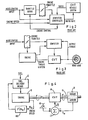
- FIG. 4 illustrates the principle functional relationships of the components of the invention which relationships are always functioning unless the power delivery system tends to enter undue operation conditions.
- An engine 10 is drivingly coupled to a continuously variable ratio transmission (CVT) 14 through a clutch or fluid coupling (not shown).
- Fuel is fed to engine 10 by a fuel delivery means 12, which may be the throttle and fuel jets of a conventional carburetor, a fuel injection system or the like.
- CVT 14 may be one of the many types of continuously variable ratio transmissions discussed above in connection with the prior art, although the V-belt traction drive type of CVT is preferred.
- Output shaft 16 delivers power and torque from the engine and CVT.
- the ratio of the CVT is set by a CVT ratio controller 17, which generates a rate of change of ratio signal R as a function of output torque To measured by torque sensor 19 and commanded power or torque a commanded by accelerator pedal 18.
- Other parameters indicative of engine-CVT system performance may be used by ratio controller 17 to effect a change of CVT ratio in a similar manner.
- CVT ratio is strictly a function of commanded power or torque and measured output torque, and is completely independent of engine operation.
- Engine control is provided by an engine controller 100 which adjusts fuel delivery means 12 in accordance with measured engine speed N E . This relationship may desirably be the ideal engine operating line for low consumption, the ideal operating line for low emissions, a compromise of the two, or any other desired engine operating characteristic.
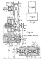
- FIG. 5 schematically illustrates the entire control system in greater detail.
- the particular type of CVT illustrated in Figure 5 is the variable diameter pulley, V-belt traction drive type having a driven sheave 20 connected to output shaft 16 and a driver sheave 30 which is coupled to engine 10.
- Belt 15 engages the grooves in the sheaves 20 and 30 to transmit motive power therebetween.
- Sheave 30 is hydraulically actuated by pressurized fluid to vary its driving diameter.
- sheave 30 has an axially fixed flange portion 32 and an axially movable flange portion 34.
- Pressurized fluid in a fluid actuation chamber 36 between fixed flange portion 32 and a piston 33 provides the axial force required to maintain flange portions 32 and 34 at a fixed distance from one another (i.e., to hold the driving diameter of sheave 30 constant), and to move flange 34 toward or away from flange 32 to vary the driving diameter.
- Hydraulic fluid is delivered to or drained from chamber 36 through a port 35; drainage is assisted by compression spring 37 located behind piston 33.
- Driven sheave 20 has an axially fixed flange portion 22 and an axially movable flange portion 24 which also is rotatable relative to fixed flange 22.
- movement of movable flange portion 24 is effected by a torque ramp assembly 25.
- load on the output shaft 16 is converted to axial force on the belt 15 in the groove between the flanges 22, 24 by several helical torque ramps 26.
- a torsion-compression spring 27 also constrains movable flange 24.
- This force has an axial component that tends to force the movable flange 24 toward the fixed flange 22, thereby raising belt tension and increasing the torque transmitted by the belt.
- the torque of spring 27 and the output torque of the drive are balanced by the belt torque.
- Transmission ratio is the quotient of driver sheave diameter and driven sheave diameter.
- commanded power or torque is applied as an hydraulic pressure (constant, increasing or decreasing) only to actuation chamber 36 of driver sheave 30. Since the distance between the sheaves 20, 30 and the length of the belt 15 are fixed, the drive diameter of driven sheave 20 will be determined by the positively controlled driving diameter of the driver sheave 30 and the output torque delivered by the belt.
- the transmission ratio R is, therefore a function of commanded power or torque a (18, Figure 4) and output torque To (19, Figure 4), with any difference between these two parameters causing a change in ratio through the inherent physical interrelationship among the sheaves and the belt (17, Figure 4), the rate of ratio change R being proportional to the difference.
- throttle (fuel delivery means) 12 is controlled by a throttle servo 13 which receives signals from engine control circuit 100.
- fuel delivery may be diminished by a fuel diminishing valve 11, or fuel delivery may be suspended completely by a fuel suspension mechanism 9.
- the fuel diminishing and suspension functions may be performed, for example, by a single solenoid valve operable in variable modes.
- Engine control circuit 100 is responsive to inputs from the accelerator pedal (accelerator position a), engine speed (N E ), a manual override switch which permits operation in the automatic or manual mode, and a start/ neutral switch (S/N) which ensures that the vehicle will remain stationary when the engine is started.
- a starting clutch 40 is provided which couples engine 10 and CVT 14. Clutch 14 is disengaged when the vehicle is stationary, and is partially. engaged during slow vehicle operation, gradually approaching full engagement, which occurs as described below at a predetermined point of operation.
- Starting clutch 40 is controlled by a control circuit 400 which is responsive to accelerator pedal position a, engine speed N EI CVT ratio R (generated by CVT ratio circuit 600 as the quotient of engine speed N E and drive shaft speed NDs), and the auto/manual switch, through servo controller 450.
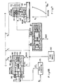
- Figures 8 and 9 schematically illustrate in greater detail the functional relationships of several of the components illustrated in Figure 5.
- Figure 8 is primarily directed to the engine control circuit 100.
- a key element of control circuit 100 is function generator 102, which may generate a function representative of any desired engine operating characteristic.
- the function ⁇ is chosen as the ideal engine operating line for low fuel consumption.
- 8 represents throttle angle, which is proportional to desired engine output torque.
- Figure 1 graphically illustrates this function as f(N E ).
- the value of the function produced by generator 102 is fed directly to throttle servo 13 via amplifier 104.
- mode switch 106 In the event the automatic control system is disabled, it is possible to switch to a manual mode through mode switch 106.
- accelerator position a is directly communicated to throttle servo 13 via amplifier 104.
- the start/ neutral switch S/N also operates through mode switch 106.
- a fuel suspension comparator 108 provides backup engine overspeed control, which may tend to occur upon vigorous acceleration, if there is a malfunction in the control system, or if belt 15 or clutch 40 should fail. Primary engine overspeed control is afforded by the hydromechanical transmission ratio control system which is described below. Comparator 108 compares engine speed N E to the maximum permissible engine speed, for example 5500 rpm.-If N e is greater than 6000 rpm, fuel suspension mechanism 9 is activated to suspend delivery of fuel to engine 10. Fuel suspension mechanism 9 may be, for example, a solenoid cutoff valve.
- Another engine speed control is provided to counteract the inherent tendency of the vehicle to speed up when the accelerator pedal is released. This phenomenon occurs because the vehicle inertia becomes coupled to the inertia of a relatively unthrottled engine through a transmission whose ratio is changing towards overdrive. This undesirable tendency is even more pronounced when the accelerator pedal is released suddenly and completely. This anomalous behavior is prevented by reducing fuel flow to the engine when pressure on the accelerator pedal is relieved, the reduction of fuel flow being proportional to the rate ( ⁇ ) at which pedal position decreases, and by reducing fuel flow even further when the accelerator pedal position a drops below 3.6% of full excursion.
- a pulse width modulator 110 controls fuel diminishing valve 11, the duty cycle (i.e., the percentage of the pulse cycle during which the fuel diminishing valve is held open) of modulator 110 being inversely proportional to the rate (-a) at which pedal position a decreases ( ⁇ a) is derived from a differentiator 112 only if 6 is less than zero.
- a fuel diminishing comparator 114 reduces the duty cycle of modulator 110 to zero or nearly to zero when pedal position a drops to below 3.6%.
- Figure 9 relates primarily to the starting clutch control circuit 400. It will be appreciated that some type of coupling must be provided between the engine and the CVT in order to permit the engine to idle while the vehicle is stationary. A fluid coupling could be used, but the mechanical losses inherent in such a device are antithetical to the desired objective of maximizing fuel economy. A torque converter with a lock-up clutch would be an improvement, but a mechanical clutch is preferred, and one which is hydraulically actuated would be well suited for this purpose. The object here, as in the conventional automobile, is to totally disengage the clutch when the vehicle is stationary, and to gradually engage it to begin vehicle movement and progressively engage the clutch further as the vehicle speed increases.
- the measured transmission ratio R (which is computed as the quotient of engine speed N E and drive shaft speed N Ds by ratio circuit 600) is fed to a comparator 402.
- Comparator 402 closes switch 404 when R exceeds 4.7 to deliver the signal from amplifier 406 to throttle servo 13 via amplifier 104.
- This signal is equal to ⁇ N E ', where N e ' is a function produced by generator 408 equal to K (N ⁇ ;-1000 rpm).
- the accelerator pedal 18 is coupled directly to throttle 12 in a variable way defined by a-N E '.
- the constant K is selected such that engine speed cannot exceed 2500 rpm if the clutch is not fully engaged. This direct coupling of accelerator pedal to throttle allows an input to be provided to the system to initiate movement of the vehicle from a stationary position.
- Comparator 402 also closes switch 410 to transmit accelerator pedal position a directly to the clutch pressure servo controller 450.
- the degree of engagement of clutch 40 is proportional to pedal position up to the point where ratio R equals 4.7.
- the degree of direct control of the accelerator pedal over throttle 12 diminishes as engine speed increases in accordance with the above-described relationship.
- a fluid source 300 supplies pressurized hydraulic fluid at a pressure P L to the various components of the system. These components include a driver control valve 310 for controlling the flow of fluid to and from actuation chamber 36 of driver sheave 30. Commands of the operator of the vehicle are input into the system by the accelerator pedal 18 which acts on pedal sensitive valve (command actuator) 320. Pedal sensitive valve 320 is mechanically coupled to driver control valve 310 and movable driver flange 34 to in effect form a proportional controller (described more fully below) for driver sheave 30.
- the sensitivity of the accelerator pedal is modulated under certain conditions by the action of an offset governor 350 which converts a regulated fluid pressure from regulator valve 302 to a pressure P G which varies as the square of drive shaft speed N os (in accordance with Figure 7) when drive shaft speed exceeds the predetermined "fast operation" value of 1173 rpm.
- an offset governor 350 which converts a regulated fluid pressure from regulator valve 302 to a pressure P G which varies as the square of drive shaft speed N os (in accordance with Figure 7) when drive shaft speed exceeds the predetermined "fast operation" value of 1173 rpm.
- the effect of pressure P G on pedal sensitive valve 320 is to diminish the mechanical displacement applied to driver control valve 310 so that the sensitivity of the accelerator pedal is diminished during relatively fast vehicle operation.
- Pressure p G also is the primary control which prevents the engine from exceeding its predetermined maximum operating speed, here 5500 rpm.
- Minimum engine speed (here 1000 rpm) is maintained by a pulse generator 370 and a switching modulator 380 which together cooperate to apply a pulsating modulating pressure P M , the duty cycle of which is proportional to the drop in engine speed below the minimum 1000 rpm to effect a proportional increase in transmission ratio, thereby decreasing the load on the engine and permitting it to speed up.
- driver control valve 310 is a known type of servo valve having a spool 312 which controls the flow of hydraulic fluid to and from driver actuation chamber 36 via ports 314 and 316 respectively.
- spool 312 has a piston 318 which controls the flow of pressurized fluid P L entering the valve through port 319.
- Piston 317 controls the flow of fluid draining from valve 310 through port 315.
- An additional port 313 admits modulating pulsating fluid pressure P m into valve 310 to act on piston 311, which has a larger exposed surface area than piston 317, and urge spool 312 to the left. As explained below, this occurs only when the speed of the engine drops below the minimum operating speed of 1000 rpm.
- spool 312 is in a position such that ports 315 and 319 are blocked, isolating the fluid in driver actuation chamber 36. Piston 33 and movable driver flange 34 are therefore immobilized. A change of transmission ratio will occur if spool 312 is moved either to the left or to the right. If moved to the right, piston 318 uncovers port 319 to permit pressurized fluid to enter valve 310 and actuation chamber 36 via port 314. This will force piston 33 to the left, thereby increasing the driving diameter of driver sheave 30 and decreasing the transmission ratio.
- Movement of spool 312 is effected primarily by the displacement output of command actuator or pedal sensitive valve 320 acting on a link 304 which pivotally interconnects movable driver flange 34 at pivot 305, spool 312 at pivot 306, and pedal sensitive valve 320 at pivot 307.
- This arrangement forms a proportional controller for driver sheave 30, the gain of which is equal to the lever ratio of the length of link 304 between pivots 305 and 306 to the length of link 304 between pivots 306 and 307.
- an initial displacement at pivot 307 will effect an immediate displacement at pivot 306 to move spool 312 and cause a change in fluid volume in actuation chamber 36.
- Command actuator or pedal sensitive valve 320 compliantly couples the accelerator pedal 18 to link 304, and also permits modulation of the commanded power or torque as a function of the vehicle speed (drive shaft speed N DS ) so as to decrease the sensitivity of the accelerator pedal during relatively fast vehicle operation.
- Pedal sensitive valve 320 comprises a housing 322 having a central bore 324 in which are coaxially slidably received a command piston 326 and a follower piston 328.
- a retaining clip 330 prevents further right hand movement of piston 326, while a retaining clip 332 prevents further right hand movement of piston 328 past the null position illustrated in Figure 6A.
- Pistons 326 and 328 are divergently biased by means of a compression compliance spring 334.
- a compression spring 336 urges piston 328 towards its null position. Movement of command piston 326 will effect compliant movement of follower piston 328 to effect a smooth actuation of change in transmission ratio.
- a modulating chamber 338 in housing 322 exposes the left face of follower piston 328 to fluid pressure P G via port 340. Fluid pressure P G in chamber 338 urges follower piston 328 to the right contrary to the leftward movement of command piston 326. The net result of this counteracting force is to diminish the sensitivity of the accelerator pedal.
- Pressure P G is generated by offset governor 350 ( Figure 6B), which is a centrifugal force responsive hydraulic valve coupled to output shaft 16.
- Offset governor 350 comprises a housing 352 which spins with output shaft 16.
- a spool 354 is axially movable within housing 352 and is biased inwardly toward the center of output shaft 16 by a return spring 356.
- An inlet port 358 receives line pressure P L from regulator valve 302.
- a drain port 360 passes draining fluid.
- a feed piston 362 on spool 354 controls the flow of hydraulic fluid into housing 352 via port 358, while a drain piston 364 controls the drain of fluid via port 360. Fluid feeds to and drains from modulating chamber 338 via port 366 in housing 352.
- Pulse generator 370 compares the actual measured engine speed N e to the minimum permissible engine speed of 1000 rpm and generates pulses only if N E is less than 1000 rpm.
- the duty cycle of pulse generator 370 is proportional to the drop in engine speed below 1000 rpm.
- Switching modulator 380 acts as a transducer to convert the electrical pulses of pulse generator 370 into pulses of hydraulic pressure P m delivered to driver control valve 310, as explained above.
- Switching modulator 380 comprises a casing 382 having a spring-loaded piston 384, a ferrous core member 386 and a . magnetic coil 388.
- Core member 386 and coil 388 act as a solenoid when energized to urge piston 384 to the right away from a stop 390 against the action of spring 392.
- Piston 384 will oscillate under the influence of pulsating current from pulse generator 370, thereby pulsatingly passing hydraulic fluid from port 394 to port 313 of driver control valve 310 via port 396 and orifice 398.
- the net modulating pressure P M applied to piston 311 to decrease the driving diameter of the driver sheave and decrease the load on the engine is therefore directly proportional to the duty cycle of pulse generator 370.
- the instant invention involves, in part, the recognition that control of the ratio rate R of the CVT, rather than merely the CVT ratio, yields improved CVT control.
- This improved control is explained by reference to the following derived vehicle performance equation:
- I CDS is car inertia reflected to the drive shaft
- NDS is vehicle acceleration measures at the drive shaft.
- rate of change of ratio is closely approximated by the following relationships: and
- the comparison of accelerator pedal position a ⁇ (commanded output torque) and output torque To occurs inherently in the belt and pulley components to effect a ratio change at a rate R.
- Other types of CVTs may require different control elements to effect this relationship.
- R is proportional to the difference between the desired performance parameter and the actual measured performance parameter.
- Figure 10 is a plot of engine speed N E as a function of vehicle speed or drive shaft speed N os .
- the minimum and maximum CVT ratios are illustrated by the straight line emanating from the origin of the graph.
- the maximum vehicle speed is defined by a vertical line at the right hand edge of the graph.
- the graph of Figure 10 is divided into a number of discrete operating regions.
- “A” designates the normal region of operation of the engine-CVT system.
- Region “A” is bounded by the line of maximum CVT ratio, the line of maximum engine speed, the line of maximum vehicle speed, the line of minimum CVT ratio and the idle speed line.
- clutch 40 is fully engaged and throttle position is wholly a function of engine speed in accordance with the fuel function f(N E ).
- Region “B” is the region of start-up control, that is, the operation of the engine-CVT system during slow vehicle operation when clutch 40 is only partially engaged.
- the control for this operation (400) is illustrated in Figure 9.
- a load line which indicates the engine speed required to maintain any constant vehicle speed along a level road.
- the term "load” includes road load, final drive losses and the like, and represents the actual load on the engine-CVT system.
- the CVT ratio range include substantially all ratios required to maintain constant vehicle speed for any normally encountered load. That is, the minimum CVT ratio preferably is smaller than that required to maintain constant vehicle speed along a level road, and the maximum CVT ratio preferably is greater than that required to maintain constant vehicle speed up the steepest grade which one might expect to encounter.
- a desirable CVT ratio range for accomplishing this is approximately 11:1 with, for example, a maximum CVT ratio of 22:1 (total vehicle ratio, including final drive ratio), and a minimum CVT ratio of 2:1.
- a CVT having smaller ratio range would be operable, but would not have as much flexibility as one with a wider range.
Landscapes
- Engineering & Computer Science (AREA)
- Mechanical Engineering (AREA)
- Chemical & Material Sciences (AREA)
- Combustion & Propulsion (AREA)
- Transportation (AREA)
- General Engineering & Computer Science (AREA)
- Automation & Control Theory (AREA)
- Control Of Driving Devices And Active Controlling Of Vehicle (AREA)
- Control Of Transmission Device (AREA)
- Transmissions By Endless Flexible Members (AREA)
Claims (17)
Applications Claiming Priority (2)
| Application Number | Priority Date | Filing Date | Title |
|---|---|---|---|
| US489177 | 1983-04-27 | ||
| US06/489,177 US4515041A (en) | 1980-05-21 | 1983-04-27 | Control system and method for a power delivery system having a continuously variable ratio transmission |
Publications (2)
| Publication Number | Publication Date |
|---|---|
| EP0126869A1 EP0126869A1 (de) | 1984-12-05 |
| EP0126869B1 true EP0126869B1 (de) | 1989-05-17 |
Family
ID=23942731
Family Applications (1)
| Application Number | Title | Priority Date | Filing Date |
|---|---|---|---|
| EP84102734A Expired EP0126869B1 (de) | 1983-04-27 | 1984-03-13 | Steuersystem für ein Kraftübertragungssystem mit einem stufenlos schaltbaren Getriebe |
Country Status (4)
| Country | Link |
|---|---|
| US (1) | US4515041A (de) |
| EP (1) | EP0126869B1 (de) |
| JP (1) | JP2687956B2 (de) |
| DE (1) | DE3478216D1 (de) |
Families Citing this family (50)
| Publication number | Priority date | Publication date | Assignee | Title |
|---|---|---|---|---|
| US4598611A (en) * | 1982-05-21 | 1986-07-08 | Aisin Seiki Kabushiki Kaisha | Low power control system and method for a power delivery system having a continuously variable ratio transmission |
| JPS59175664A (ja) * | 1983-03-23 | 1984-10-04 | Fuji Heavy Ind Ltd | 無段変速機の変速制御装置 |
| JPS59197658A (ja) * | 1983-04-26 | 1984-11-09 | Mazda Motor Corp | 自動車の駆動制御装置 |
| JPS59219553A (ja) * | 1983-05-27 | 1984-12-10 | Nissan Motor Co Ltd | 無段変速機の変速制御装置 |
| JPS6030855A (ja) * | 1983-07-30 | 1985-02-16 | Mazda Motor Corp | 無段変速機の制御装置 |
| JPS6044651A (ja) * | 1983-08-22 | 1985-03-09 | Toyota Motor Corp | 車両用無段変速機の制御方法 |
| JPS6044653A (ja) * | 1983-08-22 | 1985-03-09 | Toyota Motor Corp | 車両用無段変速機の速度比制御装置 |
| JPS6044649A (ja) * | 1983-08-22 | 1985-03-09 | Toyota Motor Corp | 車両用無段変速機の制御方法 |
| JPH066976B2 (ja) * | 1983-08-29 | 1994-01-26 | トヨタ自動車株式会社 | ベルト式無段変速機の油圧制御装置 |
| JPS6053262A (ja) * | 1983-09-01 | 1985-03-26 | Toyota Motor Corp | 車両用無段変速機の速度比制御装置 |
| JPH07113402B2 (ja) * | 1983-09-30 | 1995-12-06 | アイシン精機株式会社 | 無段変速機を用いた駆動システム装置 |
| JPS6095264A (ja) * | 1983-10-29 | 1985-05-28 | Mazda Motor Corp | 無段変速機の制御装置 |
| JPS6098253A (ja) * | 1983-10-31 | 1985-06-01 | Mazda Motor Corp | 無段変速機の制御方法 |
| JPS60159454A (ja) * | 1984-01-30 | 1985-08-20 | Fuji Heavy Ind Ltd | 無段変速機の変速制御装置 |
| JP2506630B2 (ja) * | 1984-09-13 | 1996-06-12 | アイシン精機株式会社 | Cvt制御方式 |
| JPH0623019B2 (ja) * | 1984-10-29 | 1994-03-30 | 株式会社島津製作所 | 車両用加速制御装置 |
| JPS61119861A (ja) * | 1984-11-16 | 1986-06-07 | Fuji Heavy Ind Ltd | 無段変速機の電子制御装置 |
| JPS61119860A (ja) * | 1984-11-16 | 1986-06-07 | Fuji Heavy Ind Ltd | 無段変速機の電子制御装置 |
| US4718308A (en) * | 1985-03-29 | 1988-01-12 | Borg-Warner Automotive, Inc. | Hydraulic control system for continuously variable transmission |
| US4648496A (en) * | 1985-04-12 | 1987-03-10 | Borg-Warner Automotive, Inc. | Clutch control system for a continuously variable transmission |
| KR930001391B1 (ko) * | 1985-06-12 | 1993-02-27 | 미쯔비시지도샤고교 가부시끼가이샤 | 차량용 엔진 제어장치 |
| US4699025A (en) * | 1985-09-30 | 1987-10-13 | Aisin Seiki Kabushiki Kaisha | Method and apparatus for controlling a power delivery system having a continuously variable ratio transmission |
| US4700590A (en) * | 1985-09-30 | 1987-10-20 | Aisin Seiki Kabushiki Kaisha | System for utilizing the negative torque of a power delivery system having a continuously variable ratio transmission for braking |
| US4731044A (en) * | 1985-12-18 | 1988-03-15 | Borg-Warner Automotive, Inc. | Tension sensor and control arrangement for a continuously variable transmission |
| JPS63280955A (ja) * | 1987-05-12 | 1988-11-17 | Honda Motor Co Ltd | 無段変速機の変速比制御方法および変速比制御装置 |
| EP0326274A3 (de) * | 1988-01-29 | 1991-02-06 | Fuji Jukogyo Kabushiki Kaisha | Kupplungssteuerung für ein Kraftfahrzeug |
| JP2692254B2 (ja) * | 1989-04-21 | 1997-12-17 | 日産自動車株式会社 | 無段変速機の変速制御装置 |
| US5073157A (en) * | 1990-02-20 | 1991-12-17 | Power Engineering & Manufacturing, Ltd. | Mechanically variable transmission |
| JP3200901B2 (ja) * | 1991-12-20 | 2001-08-20 | 株式会社日立製作所 | 電気自動車の駆動装置 |
| DE4411940A1 (de) * | 1994-04-07 | 1995-10-12 | Porsche Ag | Steuerverfahren und Steuereinrichtung für ein stufenloses Getriebe |
| DE19805458B4 (de) * | 1997-02-22 | 2012-05-31 | Audi Ag | Anfahrregelung für CVT-Getriebe |
| JP3800741B2 (ja) * | 1997-07-04 | 2006-07-26 | 日産自動車株式会社 | 無段変速機の足放しアップシフト変速制御装置 |
| AT3030U1 (de) * | 1998-09-01 | 1999-08-25 | Avl List Gmbh | Verfahren zur analyse und zur beeinflussung des fahrverhaltens von kraftfahrzeugen |
| JP3624741B2 (ja) * | 1999-05-17 | 2005-03-02 | 三菱自動車工業株式会社 | 無段変速機の制御装置 |
| ATE242854T1 (de) * | 1999-09-15 | 2003-06-15 | Doornes Transmissie Bv | Steuerung für ein stufenlos verstellbares getriebe bzw. ein stufenlos verstellbares getriebe mit einer derartigen steuerung |
| AUPQ700100A0 (en) * | 2000-04-18 | 2000-05-11 | Orbital Engine Company (Australia) Proprietary Limited | Engine speed control for internal combustion engines |
| US6813551B2 (en) * | 2002-02-04 | 2004-11-02 | Toyota Jidosha Kabushiki Kaisha | Control apparatus for continuously variable transmission |
| US7261672B2 (en) * | 2003-03-19 | 2007-08-28 | The Regents Of The University Of California | Method and system for controlling rate of change of ratio in a continuously variable transmission |
| US20080081734A1 (en) * | 2006-09-29 | 2008-04-03 | Caterpillar Inc. | Power system |
| KR20080041024A (ko) * | 2006-11-06 | 2008-05-09 | 현대자동차주식회사 | 무단변속기 차량의 전진/후진 감지 방법 |
| US7860631B2 (en) * | 2006-12-08 | 2010-12-28 | Sauer-Danfoss, Inc. | Engine speed control for a low power hydromechanical transmission |
| US20100100292A1 (en) * | 2007-03-01 | 2010-04-22 | Guilin Geely Stars Oil-Electric Hybrid Engine Co. | Engine servo loading device and control method for dynamic optimization searching operation of the device |
| US7552712B1 (en) * | 2007-12-13 | 2009-06-30 | Caterpillar Inc. | Part-throttle performance optimization |
| DE102010025449A1 (de) * | 2009-07-27 | 2011-02-03 | Luk Lamellen Und Kupplungsbau Beteiligungs Kg | Hydraulikanordnung zur Ansteuerung von zumindest zwei Ventilen |
| FR2997154B1 (fr) * | 2012-10-18 | 2016-03-04 | France Reducteurs | Variateur de vitesse a courroie |
| FR2997155B1 (fr) * | 2012-10-18 | 2014-11-14 | France Reducteurs | Variateur de vitesse a courroie |
| US10941840B2 (en) | 2016-06-16 | 2021-03-09 | GM Global Technology Operations LLC | Continuously variable transmission with wedge actuation mechanism |
| US11022216B2 (en) | 2016-12-01 | 2021-06-01 | Transmission Cvtcorp Inc. | CVT ratio control with respect to the actual engine torque of the prime mover |
| US10473200B2 (en) * | 2017-12-01 | 2019-11-12 | GM Global Technology Operations LLC | Continuously variable transmission with wedge actuation mechanism |
| US10473213B2 (en) | 2017-12-01 | 2019-11-12 | GM Global Technology Operations LLC | Method of controlling clamping of wedge-actuated CVT and powertrain with wedge-actuated CVT |
Citations (2)
| Publication number | Priority date | Publication date | Assignee | Title |
|---|---|---|---|---|
| US3616706A (en) * | 1968-05-18 | 1971-11-02 | Yamaha Motor Co Ltd | Transmission device of a sheave drive type |
| DE2811574A1 (de) * | 1978-03-17 | 1979-09-27 | Bosch Gmbh Robert | Vorrichtung zur regelung einer antriebsmotor-getriebe-einheit eines kraftfahrzeuges |
Family Cites Families (28)
| Publication number | Priority date | Publication date | Assignee | Title |
|---|---|---|---|---|
| US24347A (en) * | 1859-06-07 | Washing-machine | ||
| USRE24347E (en) | 1957-08-20 | Automatic variable pitch pulley | ||
| US2131157A (en) * | 1931-03-09 | 1938-09-27 | Gen Motors Corp | Control for variable speed power transmissions |
| US2059591A (en) * | 1934-07-11 | 1936-11-03 | Leoni Pilade | Automatic variable gear ratio transmission |
| US3044316A (en) * | 1955-01-07 | 1962-07-17 | Lloyd M Forster | Continuously variable transmission and automatic control |
| FR1182150A (fr) * | 1957-09-09 | 1959-06-23 | Dispositif de transmission de vitesses automatique, plus particulièrement pour véhicules automobiles | |
| US3008341A (en) * | 1959-07-06 | 1961-11-14 | Marvin E Cobb | Transmission mechanism |
| GB1035822A (en) * | 1963-01-11 | 1966-07-13 | Dowty Hydraulic Units Ltd | Infinitely variable transmission |
| US3368426A (en) * | 1965-03-12 | 1968-02-13 | Reimers Getriebe A G | Control mechanism for engine combined with infinitely variable transmission |
| US3552232A (en) * | 1966-09-26 | 1971-01-05 | Deere & Co | Transmission control |
| FR2188688A5 (de) * | 1972-06-02 | 1974-01-18 | Peugeot & Renault | |
| GB1412557A (en) * | 1972-08-23 | 1975-11-05 | Elektr Strassenverkehr Ges | Electrically propelled vehicles |
| US4023442A (en) * | 1973-08-16 | 1977-05-17 | Oklahoma State University | Automatic control means for infinitely variable transmission |
| US4008567A (en) * | 1975-04-28 | 1977-02-22 | Joseph Hirsch | Torque control system |
| GB1525861A (en) * | 1975-10-23 | 1978-09-20 | Mullard Ltd | Vehicle power transmission arrangements and electronic control means therefor |
| NL165821C (nl) * | 1976-02-09 | 1981-05-15 | Doornes Transmissie Bv | Traploos variabele overbrenging. |
| DE2642738C2 (de) * | 1976-09-23 | 1986-08-07 | Robert Bosch Gmbh, 7000 Stuttgart | Verfahren zur Regelung des Betriebsverhaltens einer Brennkraftmaschine in einem vorgegebenen Betriebsbereich |
| US4091690A (en) * | 1976-09-28 | 1978-05-30 | Aisin Seiki Kabushiki Kaisha | Method for controlling continuously variable drive ratio transmissions and a system therefor |
| JPS5472359A (en) * | 1977-11-21 | 1979-06-09 | Aisin Seiki Co Ltd | Speed ratio control system for stageless speed change gear in vehicle |
| IE46274B1 (en) * | 1977-12-12 | 1983-04-20 | Kiely Denis Martin | A variable speed drive for a battery-powered electric vehicle |
| DE2843256A1 (de) * | 1978-10-04 | 1980-04-17 | Bosch Gmbh Robert | Vorrichtung zur regelung einer kraftfahrzeug-antriebseinheit |
| DE2933714A1 (de) * | 1979-08-21 | 1981-03-26 | Volkswagen Ag, 38440 Wolfsburg | Aus einem verbrennungsmotor und einem nachgeordneten, automatisch schaltbaren getriebe bestehendes antriebsaggregat fuer fahrzeuge, insbesondere kraftfahrzeuge |
| JPS56153147A (en) * | 1980-04-30 | 1981-11-27 | Aisin Warner Ltd | Oil pressure regulating device for v-belt type stepless speed changing apparatus for vehicle |
| JPS5839870A (ja) * | 1981-09-03 | 1983-03-08 | Nissan Motor Co Ltd | エンジン・無段変速機駆動系統の制御装置 |
| DE3138371A1 (de) * | 1981-09-26 | 1983-04-14 | Daimler-Benz Ag, 7000 Stuttgart | "vorrichtung zur regelung einer antriebsmotor-getriebe-einheit eines kraftfahrzeuges |
| JPS58160661A (ja) * | 1982-03-17 | 1983-09-24 | Toyota Motor Corp | 車両用動力装置 |
| US4458560A (en) * | 1982-05-21 | 1984-07-10 | Aisin Seiki Kabushiki Kaisha | Control system and method for a power delivery system having a continuously variable ratio transmission |
| US4458561A (en) * | 1982-05-21 | 1984-07-10 | Frank Andrew A | Control system and method for a power delivery system having a continuously variable ratio transmission |
-
1983
- 1983-04-27 US US06/489,177 patent/US4515041A/en not_active Expired - Lifetime
-
1984
- 1984-03-13 EP EP84102734A patent/EP0126869B1/de not_active Expired
- 1984-03-13 DE DE8484102734T patent/DE3478216D1/de not_active Expired
- 1984-03-30 JP JP59064330A patent/JP2687956B2/ja not_active Expired - Lifetime
Patent Citations (2)
| Publication number | Priority date | Publication date | Assignee | Title |
|---|---|---|---|---|
| US3616706A (en) * | 1968-05-18 | 1971-11-02 | Yamaha Motor Co Ltd | Transmission device of a sheave drive type |
| DE2811574A1 (de) * | 1978-03-17 | 1979-09-27 | Bosch Gmbh Robert | Vorrichtung zur regelung einer antriebsmotor-getriebe-einheit eines kraftfahrzeuges |
Also Published As
| Publication number | Publication date |
|---|---|
| EP0126869A1 (de) | 1984-12-05 |
| US4515041A (en) | 1985-05-07 |
| JPS608557A (ja) | 1985-01-17 |
| JP2687956B2 (ja) | 1997-12-08 |
| DE3478216D1 (en) | 1989-06-22 |
Similar Documents
| Publication | Publication Date | Title |
|---|---|---|
| EP0126869B1 (de) | Steuersystem für ein Kraftübertragungssystem mit einem stufenlos schaltbaren Getriebe | |
| EP0095173B1 (de) | Steuersystem und -verfahren für ein System zur Leistungsabgabe mit einem stufenlosen Getriebe | |
| EP0095147B1 (de) | Steuersystem und -verfahren für ein leistungsabgebendes System mit einem stufenlosen Getriebe | |
| US4598611A (en) | Low power control system and method for a power delivery system having a continuously variable ratio transmission | |
| US4699025A (en) | Method and apparatus for controlling a power delivery system having a continuously variable ratio transmission | |
| US4161894A (en) | Automatic transmission device, with belt transmission ratio variator, particularly for motor vehicles | |
| US4580465A (en) | Microprocessor controlled system and method for reducing the fuel flow to the prime mover of a power delivery system having a continuously variable ratio transmission upon a commanded decrease in power delivery | |
| US4700590A (en) | System for utilizing the negative torque of a power delivery system having a continuously variable ratio transmission for braking | |
| US4543077A (en) | Method and apparatus for controlling continuously variable V-belt transmission | |
| US4641553A (en) | Control system and method for a power delivery system having a continuously variable ratio transmission | |
| US4733582A (en) | Control valve system for a continuously variable belt driven transmission for motor vehicles | |
| US4458561A (en) | Control system and method for a power delivery system having a continuously variable ratio transmission | |
| US4593581A (en) | Microprocessor controlled system and method for increasing the fuel flow to the prime mover of a power delivery system having a continuously variable ratio transmission upon a commanded increase in power delivery | |
| US4612827A (en) | Accelerator control for a vehicular propulsion system having a continuously variable ratio transmission | |
| US4686871A (en) | Power delivery system having a continuously variable ratio transmission | |
| US7534194B2 (en) | Vehicular transmission | |
| US5012697A (en) | Revolution controller for a continuously variable transmission | |
| JP4362943B2 (ja) | 無段変速機の変速制御装置 | |
| JPH08312741A (ja) | 無段自動変速機の制御装置 | |
| JPH0285559A (ja) | 車両用無段変速機の変速比制御方法 | |
| JPS6367062B2 (de) | ||
| JPS6098252A (ja) | 電子制御式無段変速装置 | |
| JPH07109236B2 (ja) | 車両用自動変速機におけるトルクコンバ−タの直結制御装置 | |
| JPH0474582B2 (de) |
Legal Events
| Date | Code | Title | Description |
|---|---|---|---|
| PUAI | Public reference made under article 153(3) epc to a published international application that has entered the european phase |
Free format text: ORIGINAL CODE: 0009012 |
|
| AK | Designated contracting states |
Designated state(s): DE FR GB IT SE |
|
| 17P | Request for examination filed |
Effective date: 19841130 |
|
| 17Q | First examination report despatched |
Effective date: 19860306 |
|
| GRAA | (expected) grant |
Free format text: ORIGINAL CODE: 0009210 |
|
| AK | Designated contracting states |
Kind code of ref document: B1 Designated state(s): DE FR GB IT SE |
|
| ITF | It: translation for a ep patent filed | ||
| REF | Corresponds to: |
Ref document number: 3478216 Country of ref document: DE Date of ref document: 19890622 |
|
| ET | Fr: translation filed | ||
| PLBE | No opposition filed within time limit |
Free format text: ORIGINAL CODE: 0009261 |
|
| STAA | Information on the status of an ep patent application or granted ep patent |
Free format text: STATUS: NO OPPOSITION FILED WITHIN TIME LIMIT |
|
| 26N | No opposition filed | ||
| PGFP | Annual fee paid to national office [announced via postgrant information from national office to epo] |
Ref country code: GB Payment date: 19910304 Year of fee payment: 8 |
|
| PGFP | Annual fee paid to national office [announced via postgrant information from national office to epo] |
Ref country code: SE Payment date: 19910320 Year of fee payment: 8 |
|
| ITTA | It: last paid annual fee | ||
| PGFP | Annual fee paid to national office [announced via postgrant information from national office to epo] |
Ref country code: DE Payment date: 19910402 Year of fee payment: 8 |
|
| PGFP | Annual fee paid to national office [announced via postgrant information from national office to epo] |
Ref country code: FR Payment date: 19911223 Year of fee payment: 9 |
|
| PG25 | Lapsed in a contracting state [announced via postgrant information from national office to epo] |
Ref country code: GB Effective date: 19920313 |
|
| PG25 | Lapsed in a contracting state [announced via postgrant information from national office to epo] |
Ref country code: SE Effective date: 19920314 |
|
| GBPC | Gb: european patent ceased through non-payment of renewal fee | ||
| PG25 | Lapsed in a contracting state [announced via postgrant information from national office to epo] |
Ref country code: DE Effective date: 19921201 |
|
| PG25 | Lapsed in a contracting state [announced via postgrant information from national office to epo] |
Ref country code: FR Effective date: 19931130 |
|
| REG | Reference to a national code |
Ref country code: FR Ref legal event code: ST |
|
| EUG | Se: european patent has lapsed |
Ref document number: 84102734.5 Effective date: 19921005 |