EP0127094B1 - Dispositif de suspension active - Google Patents
Dispositif de suspension active Download PDFInfo
- Publication number
- EP0127094B1 EP0127094B1 EP84105705A EP84105705A EP0127094B1 EP 0127094 B1 EP0127094 B1 EP 0127094B1 EP 84105705 A EP84105705 A EP 84105705A EP 84105705 A EP84105705 A EP 84105705A EP 0127094 B1 EP0127094 B1 EP 0127094B1
- Authority
- EP
- European Patent Office
- Prior art keywords
- hydropneumatic
- signal
- relative displacement
- circuit
- component
- Prior art date
- Legal status (The legal status is an assumption and is not a legal conclusion. Google has not performed a legal analysis and makes no representation as to the accuracy of the status listed.)
- Expired
Links
- 239000000725 suspension Substances 0.000 title claims description 55
- 238000006073 displacement reaction Methods 0.000 claims description 60
- 238000013016 damping Methods 0.000 claims description 38
- 230000001788 irregular Effects 0.000 claims description 4
- 239000012530 fluid Substances 0.000 description 12
- 238000012935 Averaging Methods 0.000 description 4
- 238000010586 diagram Methods 0.000 description 4
- 238000011156 evaluation Methods 0.000 description 4
- 230000015556 catabolic process Effects 0.000 description 3
- 238000006731 degradation reaction Methods 0.000 description 3
- 230000001133 acceleration Effects 0.000 description 2
- 230000000694 effects Effects 0.000 description 2
- 239000000284 extract Substances 0.000 description 2
- 238000009434 installation Methods 0.000 description 2
- 238000012545 processing Methods 0.000 description 2
- 229920001875 Ebonite Polymers 0.000 description 1
- 239000006096 absorbing agent Substances 0.000 description 1
- 239000003990 capacitor Substances 0.000 description 1
- 230000006835 compression Effects 0.000 description 1
- 238000007906 compression Methods 0.000 description 1
- 230000008602 contraction Effects 0.000 description 1
- 238000007796 conventional method Methods 0.000 description 1
- 230000003247 decreasing effect Effects 0.000 description 1
- 238000001514 detection method Methods 0.000 description 1
- 238000002474 experimental method Methods 0.000 description 1
- 239000000446 fuel Substances 0.000 description 1
- 230000014509 gene expression Effects 0.000 description 1
- 230000000750 progressive effect Effects 0.000 description 1
- 230000002441 reversible effect Effects 0.000 description 1
- 238000005096 rolling process Methods 0.000 description 1
- 230000009291 secondary effect Effects 0.000 description 1
- 230000035939 shock Effects 0.000 description 1
- 238000012360 testing method Methods 0.000 description 1
- 230000001052 transient effect Effects 0.000 description 1
Images




Classifications
-
- B—PERFORMING OPERATIONS; TRANSPORTING
- B60—VEHICLES IN GENERAL
- B60G—VEHICLE SUSPENSION ARRANGEMENTS
- B60G17/00—Resilient suspensions having means for adjusting the spring or vibration-damper characteristics, for regulating the distance between a supporting surface and a sprung part of vehicle or for locking suspension during use to meet varying vehicular or surface conditions, e.g. due to speed or load
- B60G17/015—Resilient suspensions having means for adjusting the spring or vibration-damper characteristics, for regulating the distance between a supporting surface and a sprung part of vehicle or for locking suspension during use to meet varying vehicular or surface conditions, e.g. due to speed or load the regulating means comprising electric or electronic elements
- B60G17/016—Resilient suspensions having means for adjusting the spring or vibration-damper characteristics, for regulating the distance between a supporting surface and a sprung part of vehicle or for locking suspension during use to meet varying vehicular or surface conditions, e.g. due to speed or load the regulating means comprising electric or electronic elements characterised by their responsiveness, when the vehicle is travelling, to specific motion, a specific condition, or driver input
- B60G17/0165—Resilient suspensions having means for adjusting the spring or vibration-damper characteristics, for regulating the distance between a supporting surface and a sprung part of vehicle or for locking suspension during use to meet varying vehicular or surface conditions, e.g. due to speed or load the regulating means comprising electric or electronic elements characterised by their responsiveness, when the vehicle is travelling, to specific motion, a specific condition, or driver input to an external condition, e.g. rough road surface, side wind
-
- B—PERFORMING OPERATIONS; TRANSPORTING
- B60—VEHICLES IN GENERAL
- B60G—VEHICLE SUSPENSION ARRANGEMENTS
- B60G7/00—Pivoted suspension arms; Accessories thereof
- B60G7/04—Buffer means for limiting movement of arms
-
- B—PERFORMING OPERATIONS; TRANSPORTING
- B60—VEHICLES IN GENERAL
- B60G—VEHICLE SUSPENSION ARRANGEMENTS
- B60G2400/00—Indexing codes relating to detected, measured or calculated conditions or factors
- B60G2400/10—Acceleration; Deceleration
- B60G2400/102—Acceleration; Deceleration vertical
-
- B—PERFORMING OPERATIONS; TRANSPORTING
- B60—VEHICLES IN GENERAL
- B60G—VEHICLE SUSPENSION ARRANGEMENTS
- B60G2400/00—Indexing codes relating to detected, measured or calculated conditions or factors
- B60G2400/25—Stroke; Height; Displacement
- B60G2400/252—Stroke; Height; Displacement vertical
-
- B—PERFORMING OPERATIONS; TRANSPORTING
- B60—VEHICLES IN GENERAL
- B60G—VEHICLE SUSPENSION ARRANGEMENTS
- B60G2400/00—Indexing codes relating to detected, measured or calculated conditions or factors
- B60G2400/50—Pressure
-
- B—PERFORMING OPERATIONS; TRANSPORTING
- B60—VEHICLES IN GENERAL
- B60G—VEHICLE SUSPENSION ARRANGEMENTS
- B60G2400/00—Indexing codes relating to detected, measured or calculated conditions or factors
- B60G2400/80—Exterior conditions
- B60G2400/82—Ground surface
-
- B—PERFORMING OPERATIONS; TRANSPORTING
- B60—VEHICLES IN GENERAL
- B60G—VEHICLE SUSPENSION ARRANGEMENTS
- B60G2500/00—Indexing codes relating to the regulated action or device
- B60G2500/10—Damping action or damper
-
- B—PERFORMING OPERATIONS; TRANSPORTING
- B60—VEHICLES IN GENERAL
- B60G—VEHICLE SUSPENSION ARRANGEMENTS
- B60G2600/00—Indexing codes relating to particular elements, systems or processes used on suspension systems or suspension control systems
- B60G2600/12—Sampling or average detecting; Addition or substraction
-
- B—PERFORMING OPERATIONS; TRANSPORTING
- B60—VEHICLES IN GENERAL
- B60G—VEHICLE SUSPENSION ARRANGEMENTS
- B60G2600/00—Indexing codes relating to particular elements, systems or processes used on suspension systems or suspension control systems
- B60G2600/14—Differentiating means, i.e. differential control
-
- B—PERFORMING OPERATIONS; TRANSPORTING
- B60—VEHICLES IN GENERAL
- B60G—VEHICLE SUSPENSION ARRANGEMENTS
- B60G2600/00—Indexing codes relating to particular elements, systems or processes used on suspension systems or suspension control systems
- B60G2600/18—Automatic control means
- B60G2600/182—Active control means
-
- B—PERFORMING OPERATIONS; TRANSPORTING
- B60—VEHICLES IN GENERAL
- B60G—VEHICLE SUSPENSION ARRANGEMENTS
- B60G2600/00—Indexing codes relating to particular elements, systems or processes used on suspension systems or suspension control systems
- B60G2600/60—Signal noise suppression; Electronic filtering means
- B60G2600/604—Signal noise suppression; Electronic filtering means low pass
-
- Y—GENERAL TAGGING OF NEW TECHNOLOGICAL DEVELOPMENTS; GENERAL TAGGING OF CROSS-SECTIONAL TECHNOLOGIES SPANNING OVER SEVERAL SECTIONS OF THE IPC; TECHNICAL SUBJECTS COVERED BY FORMER USPC CROSS-REFERENCE ART COLLECTIONS [XRACs] AND DIGESTS
- Y10—TECHNICAL SUBJECTS COVERED BY FORMER USPC
- Y10S—TECHNICAL SUBJECTS COVERED BY FORMER USPC CROSS-REFERENCE ART COLLECTIONS [XRACs] AND DIGESTS
- Y10S280/00—Land vehicles
- Y10S280/01—Load responsive, leveling of vehicle
Definitions
- the present invention relates to an active suspension apparatus incorporating a hydropneumatic spring for suspending a vehicle body on wheels by using a hydropneumatic pressure, comprising: displacement detecting means for detecting a relative displacement between an axle and the vehicle body; hydropneumatic suspension means having hydropneumatic springs with hydropneumatic chambers and actuators; controller means for electronically controlling the damping force of the hydropneumatic springs in accordance with predetermined characteristics.
- a hydropneumatic independent wheel vehicle suspension system which comprises a cylinder and piston suspension device having a hydraulic fluid compartment and a pneumatic fluid compartment supports a spring mass of the vehicle of an axle shaft of a vehicle wheel.
- This known system further comprises a vehicle speed transducer mounted on the vehicle for providing a speed signal representing the vehicle speed, furthermore a position transducer providing a position signal representing the extension of the suspension device, furthermore processing means for generating a reference signal proportional to the reciprocal square root of the position signal according to a predetermined proportionality factor, a difference circuit having a direct input connected to the speed transducer and an inverting input connected to the processing means for generating a difference signal proportional to the difference of the speed signal and the reference signal, and means driven by the difference signal to discharge fluid from the pneumatic fluid compartment if the difference signal is greater than zero by more than a predetermined threshold, and to supply fluid to the pneumatic compartment if the difference signal is less than zero by more than the threshold.
- the present invention has been made to overcome the conventional drawbacks, and has as its object to provide an active suspension apparatus capable of optimally controlling the characteristics of damping force of a hydropneumatic suspension in accordance with an actual condition of a road on which a vehicle is riding, improving greatly riding comfort on both smooth and rough roads, and contributing to high stability and controllability.
- the active suspension apparatus further comprises discriminating means for discriminating a travel road surface state in accordance with a sum (Ax+Bx) of a signal obtained by multiplying the relative displacement with a first coefficient and a signal obtained by multiplying a change rate in unit time of the relative displacement with a second coefficient, the first and second coefficients being determined in accordance with riding comfort against vibrations; and driving means for controlling opening areas of throttle valves, disposed between said hydropneumatic chamber and said actuators, in accordance with a road surface state signal supplied from said discriminating means, whereby characteristics of a damping force are controlled in accordance with the road surface state signal.
- the attenuation force is controlled by adjusting the opening area of the throttle valve arranged between the pneumatic chamber and the actuator, and thus has an effect of directly attenuating the vibration of the suspension apparatus.
- the discriminating means comprises: a differentiator for differentiating the relative displacement x detected by the displacement detecting means and for producing a change rate (x) of the relative displacement; a selecting circuit for extracting a component (x ⁇ ) corresponding to an expanded side of said hydropneumatic springs and a component (x-) corresponding to a compressed side of said hydropneumatic spring in accordance with the change rate (x) of the relative displacement which is generated from the differentiator; an operation circuit for multiplying with different coefficients the relative displacement (x) and the components ( ⁇ + and ⁇ -) extracted from the selecting circuit and for adding resultant products; and a comparator for comparing an output generated from the operation circuit with a reference value and for generating the road surface state signal.
- the selecting circuit in the discriminating means comprises: a first half wave detecting circuit for extracting the component (x +) of one polarity corresponding to the expanded side of said hydropneumatic spring from a signal which represents the change rate (x) in unit time and which is generated from the differentiator, and for producing an absolute value of the extracted component; and a second half wave detecting circuit for extracting the component ( k -) of the other polarity corresponding to the compressed side of said hydropneumatic spring from the signal which represents the change rate (x) in unit time and which is generated from the differentiator, and for producing an absolute value of the extracted component.
- the discriminating means further has a full wave linear detecting circuit for generating a signal corresponding to an absolute value of the relative displacement (x) detected by the displacement detecting means.
- the operation circuit multiplies with the respective coefficients the outputs which are generated from the full wave linear detecting circuit and the first and second half wave detecting circuits, and adds the resultant products.
- the operation circuit multiplies the signal component corresponding to the expanded hydropneumatic spring with a larger coefficient than that of the signal component corresponding to the compressed side of said hydropneumatic spring.
- the operator compares the signal generated from the operation circuit with a predetermined reference signal.
- the comparator When the signal is smaller than the reference signal, the comparator generates a first signal representing that the vehicle is riding on a smooth road surface. However, when the signal is larger than the reference signal, the comparator . generates a second signal representing that the vehicle is riding on a rough road surface.
- the throttle valve of the hydropneumatic suspension means comprises first and second orifices, and is controlled by the driving means such that both first and second orifices having respective predetermined opening areas are opened when a discrimination result from the discriminating means indicates a smooth road surface, and that the either first or the second orifice is opened when the discrimination result from the discriminating means indicates a rough road surface.
- the travel state of a vehicle can be represented by a relative displacement x between each axle and a vehicle body and by its change rate in unit time (i.e., relative velocity x).
- the relative displacement x is plotted along the abscissa
- the relative velocity x is plotted along the ordinate.
- the travel state given by a road surface state, a vehicle speed and so on is given by a point in the xx coordinate system.
- the present inventors have performed test drives at different operating conditions on roads having different surface states so as to determine the relationship between the relative displacement between the axle and the vehicle body and the change rate x in unit time.
- both the values of the displacement x and the change rate x became large, resulting in poor riding comfort and often unstable operation (i.e., degradation of stability and controllability).
- a sum (x+x) of the displacement x and the change rate x exceeded a predetermined value although neither the displacement x was large or the change rate x was high, vibrations occurred to degrade riding comfort and other factors.
- the present inventors therefore, identified the relationship between a road surface state and the sum of the displacement x and the change rate k, and variously controlled the characteristics of damping forces of the hydropneumatic suspension in accordance with this relationship.
- the present inventors found that the contributions of the displacement x and the change rate x to the riding comfort and other factors were different from each other, and that multiplication of specific coefficients with the displacement x and the change rate x improved the riding comfort. In other words, it was found out that the coefficients A and B for obtaining the sum (Ax+Bx) must have a predetermined ratio.
- the displacement x and the corresponding change rates x must change to have a predetermined ratio at the expanded and compressed hydropneumatic springs.
- Ax+BCsx and Ax+BCcx must be taken account where Cs is the velocity coefficient at the expanded hydropneumatic spring and Cc is the velocity coefficient at the compressed one.
- the characteristics of damping force of the hydropneumatic suspension in the triangular areas surrounded by the x-axis, the x-axis and the lines P and Q must differ from that in any other area so as to improve riding comfort against vibrations.
- These triangular areas must be given within an appropriate range.
- the present inventors found the appropriate triangular areas in accordance with experiments. The present inventors determined that the triangular areas correspond to the range within which the both values of displacements x and the corresponding change rates x fell when the vehicle travelled on smooth and normal roads, and that the area excluding the triangular areas correspond to the range when the vehicle travelled on a rough road.
- evaluation values Ys and -Yc at the expanded and compressed hydropneumatic springs are: where A and B are the coefficients representing the contribution factors of the relative displacement and the relative velocity, respectively, and Cs and Cc are the velocity coefficients at the expanded and compressed springs.
- Equations (1) and (2) above are plotted as the lines P and Q in Fig. 1.
- reference values for evaluating motion are given as Rs and -Rc
- comparison among Ys, Rs, -Yc and -Rc discriminates whether a given road state corresponds to a rough road state or a smooth or normal road state.
- the characteristics of the damping forces of the hydropneumatic suspension can be controlled in accordance with the discrimination result, thereby obtaining an optimal travel state.
- Fig. 2 is a graph showing a two-step control operation wherein higher and lower damping forces are switched in accordance with the discrimination result.
- the relative velocity x is plotted along the abscissa and damping force Fd is plotted along the ordinate.
- the switching points of the two-step damping forces Fd are determined in accordance with the values Cs and Cc of equations (1) and (2) above for determining the triangular areas in Fig. 1 and the reference values Rs and -Rc, and are given to be f(Cs) and f(Cc) in Fig. 2.
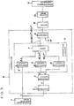
- Fig. 3 is a block diagram showing the basic arrangement of the active suspension apparatus according to the present invention.
- a controller II of the active suspension apparatus comprises: a differentiator 1 for differentiating the relative displacement x detected by a displacement detecting means I and for generating the corresponding change rate x in unit time; a selecting circuit 2 for extracting a component x corresponding to the expanded hydropneumatic spring and a component ⁇ - corresponding to the compressed hydropneumatic spring from the change rate x generated from the differentiator 1; an operation circuit 3 for multiplying the respective coefficients with the relative displacement x and the components ⁇ + and ⁇ - extracted from the selecting circuit 2 and for adding the resultant products; and a comparator 8 for comparing the signal (Ax+BCsx or Ax+BCcx) with the reference value which determines the corresponding triangular area, and for generating a road surface state signal.
- the operation circuit 3 comprises coefficient circuits 4 to 6 and an adder 7.
- the comparator 8 in the controller II supplies a signal to a driver III when a combination of the relative displacement x and its change rate x is plotted outside the triangular areas.
- the driver III amplifies the signal supplied from the comparator 8, and an amplified signal is supplied to a driving means IV.
- the driving means IV controls the opening of a throttle valve disposed between each actuator and the hydropneumatic chamber of the corresponding hydropneumatic spring in a hydropneumatic suspension V.
- the driving means is controlled to obtain a high damping force.
- Ys or Yc is smaller than Rs or Rc (i.e., when the vehicle is detected to ride on smooth and normal road surfaces)
- a low damping force is obtained.
- the characteristics of damping force of the hydropneumatic suspension are controlled in accordance with the road surface states, so that the vibrations can be effectively absorbed by a strong damping force when the vehicle rides on a rough road surface, and that a weak damping force acts to prevent degradation of riding comfort when the vehicle rides on smooth and normal road surfaces.
- vibrations can be effectively absorbed by the high characteristic of the damping force.
- the appropriate damping force acts on the hydropneumatic suspension in accordance with the given road surface state, so that riding comfort, and stability and controllability can be greatly improved.
- the active suspension apparatus basically comprises the displacement detecting means I, the controller 11, the driver III, the driving means IV and the hydropneumatic suspension V, as shown in Fig. 3.
- the displacement detecting means I comprises four bar type potentiometers 10a, 10b, 10c and 10d between the vehicle body, trailing arms and lower arms for rotatably supporting the front and rear axles of the front and rear wheels.
- the displacement detecting means I detects the relative displacements between the axles and the vehicle body while the vehicle is travelling.
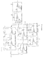
- the controller II comprises a full wave linear detecting circuit 11 connected to the potentiometer 10c as the output stage of the displacement detecting means I, a differentiator 12 connected to the displacement detecting means I, a first half wave linear detecting circuit 13 connected to the differentiator 12, a reversing circuit 14, a second half wave linear detecting circuit 15 connected to the reversing circuit 14, an operation circuit 16 connected to outputs of the respective detecting circuits 11, 13 and 15, and a comparator 17 for comparing an output generated from the operation circuit 16 with a reference value.
- the full wave linear detecting circuit 11 comprises a half wave rectifier constituted by an operational amplifier OP1, resistors R1 and R2 and diodes D1 and D2 so as to invert and amplify a positive half cycle, and an inverting adder constituted by an operational amplifier OP2 and resistors R3 to R5.
- the full wave linear detecting circuit 11 generates a signal (i.e., signal Ixl corresponding to the absolute value of the relative displacement x) obtained by full-wave rectifying the relative displacement x. In this manner, the full wave linear detecting circuit 11 always generates an absolute value signal irrespective of expanding and compression of the hydropneumatic spring.
- the differentiator 12 comprises a conventional differentiator constituted by an operational amplifier OP3, a capacitor C and a resistor R6.
- the differentiator 12 generates a signal -x obtained by differentiating the relative displacement x and inverting the differentiated signal.
- a circuit constituted by the reversing circuit 14 and the first and second half wave linear detecting circuits 13 and 15 extracts components (to be referred to as ⁇ + and ⁇ - ) of the change rate x which correspond to the expanded and compressed hydropneumatic springs.
- the above circuit then generates absolute values
- the first half wave linear detecting circuit 13 comprises an operational amplifier OP4, resistors R7 and R8 and diodes D3 and D4 and linearly detects the half wave so as to extract the component k + , i.e., the negative component (positive component of the change rate signal x corresponding to the expanded hydropneumatic spring) of the output signal -x from the differentiator 12.
- the first half wave linear detecting circuit 13 then generates the output signal k + .
- the reversing circuit 14 comprises an operational amplifier OP5 and resistors R9 and R10 and inverts the output signal -x generated from the differentiator 12. In other words, the positive component is inverted to the negative component and vice versa, thereby generating the change rate signal x.
- the second half wave linear detecting circuit 15 comprises an operational amplifier OP6, resistors R11 and R12, and diodes D5 and D6, and extracts the negative component (i.e., the component ⁇ - corresponding to the compressed hydropneumatic spring) of the output signal x generated from the reversing circuit 14.
- the second half wave linear detecting circuit 15 then performs linear detection so as to generate the extracted component as the absolute value signal
- the operation circuit 16 comprises resistors R13 to R16 and an operational amplifier OP7.
- the operation circuit 16 multiplies with the corresponding coefficients the output signals IxI, Ix+ ⁇ and lx-I respectively generated from the full wave linear detecting circuit 11 and the first and second half wave linear detecting circuits 13 and 15, and performs reverse addition.
- the resistances of the resistors R13 to R16 are selected to give the coefficients A, BCs and BCc of equations (1) and (2) above.
- the resistances of the resistors R13, R14 and R15 are set to be R16/A, R16/BCs and R16/BCc.
- the operation circuit 16 when the hydropneumatic spring is compressed, the operation circuit 16 generates an output A
- the comparator 17 comprises a resistor R17, an operational amplifier OP8 and a reference power supply -E.
- the comparator 17 comprises the output signal generated from the operation circuit 16 with the reference voltage. When the output signal is higher than the reference voltage, the comparator 17 generates a signal.
- the driver III (illustrated only in Fig. 3) is connected to the comparator 17 of the controller II and amplifiers the output signal generated from the comparator 17 so as to drive the driving means IV.
- the hydropneumatic suspension V of the apparatus of this embodiment is a trailing arm type suspension for the rear axle and comprises an actuator disposed between an independently movable arm and the vehicle body, a damping force generating throttle device with orifices, a hydropneumatic spring and a rubber bushing of nonlinear spring characteristics.
- the driving means IV constitutes a magnetic valve for changing the throttle valve so as to control the damping force generating throttle device with orifices in response to the signal generated from the driver III.
- Throttle devices 20 and 21 are disposed to communicate with hydraulic actuators 22 and 23 and further with accumulators of hydropneumatic springs 24 and 25, respectively.
- Magnetic valves 26 and 27 for changing the corresponding throttle valves serves as the driving means IV driven by the driver III and are mounted on the throttle devices 20 and 21, respectively.
- Each of the throttle devices 20 and 21 has flow paths 20-1 and 20-2 as major flow paths which extend through first and second orifices 28 and 29 as throttle valves, respectively, as shown in Fig. 7 (only the device 20 is shown in Fig. 7).
- the flow path 20-1 is a straight path extending through the device 20.
- the flow path 20-2 flows in the magnetic valve 26 and returns through an of/off pipe.
- the magnetic valve 26 for changing the throttle valve is controlled such that the fluid flows through only the first orifice 28 or that the fluid flows through both the first and second orifices 28 and 29. In this manner, the opening of the throttle- valve is controlled to adjust the damping force.
- the magnetic valve 26 is controlled to cause the fluid to flow through the first and second orifices to weaken the damping forces of the hydropneumatic suspension 24.
- the magnetic valve 26 is driven to close the second orifice 29, while the first orifice 29 is kept opened, thereby increasing the damping force.
- the fluid compressed by a hydraulic pump 30 has a predetermined pressure.
- the compressed fluid is stored in a hydropneumatic accumulator 31.
- magnetic valves 33a and 33b are turned on/off, and the pump is started/stopped.
- the compressed fluid is supplied to the actuators 22 and 23 through the magnetic valves 33a and 33b, respectively, thereby performing height control of the vehicle under the control of the electrical circuit 32.
- the active suspension comprises the actuators 22 and 23, the damping force throttle devices 20 and 21 with the orifices 28 and 29, the magnetic valves 26 and 27 for changing the corresponding throttle valves, rubber bushings 40 and 41 (Fig. 8) of nonlinear spring characteristics, and the hydropneumatic springs 24 and 25.
- the active suspension is installed between a trailing arm 42 and a vehicle body 43, as shown in Fig. 8.
- the installation of the actuator of the active suspension and the rubber bushing of nonlinear spring characteristics will now be described in more detail with reference to Fig. 8. For illustrative convenience, only the unit for the rear left wheel is exemplified.
- the trailing arm 42 of the suspension system which holds the corresponding wheel is held through a rear suspension member 44.
- an actuator mounting cylinder 45 is welded on the vehicle body.
- an actuator mounting portion 46 is welded to the trailing arm 42.
- the boot column of the active suspension is mounted on and fixed to the mounting portion 46 of the boot column.
- the actuator is fixed to the actuator mounting cylinder 45 through a set screw 45a so as to compensate for the working force between the vehicle body 43 and the suspension system.
- the actuator mounting cylinder 45 is mounted on the vehicle body in such a reinforced manner that abutment plates 47 and 48 are respectively welded to the upper and lower surfaces of the body 43. In this case, when hard rubber buffer rings 49 and 50 are inserted between the body 43 and the mounting cylinder 45, vibrations and noise can be greatly decreased.
- the installation of the rubber bushings 40 and 41 of nonlinear spring characteristics will be described.
- the rubber bushings 40 and 41 are fixed by bush holding bolts 53 on bush holding arms 52 and 51, respectively. End portions of the bush holding arms 51 and 52 are supported on the suspension member 44.
- the shape of the rubber bushings may be an irregular pyramid having a top point offset from the center thereof as shown in Figs. 9A and 9B or an irregular elliptic cone having a top point offset from the center thereof as shown in Figs. 9C and 9D, since the rotational displacement of the arm is increased in accordance with an increase in radius of the arm rotation.
- the distortions of the bushings 40 and 41 are increased in accordance with an increase in radius of rotation ofthe trailing arm 42. Therefore, when the shape of the rubber bushings 40 and 41 is formed such that a center of deformation is gradually shifted toward a large radius direction, the center of the load is smoothly and stably shifted, thereby obtaining smooth nonlinear characteristics of the relationship between the displacement as a result of contact between the rubber bushings40 and 41 and the trailing arm 42 and the resultant spring force.
- the nonlinear spring characteristics are given as a change in spring force Fk as a function of the relative displacement x, as shown in Fig. 10.
- a curve nom is a characteristic curve obtained by only the gas spring force;
- a curve qs shows a characteristic curve obtained by only the rubber bushing 41 at the contraction stroke; and
- a curve pr is a characteristic curve obtained by only the rubber bushing 40 at the expanding stroke.
- the overall spring characteristics have a hysteresis indicated by the solid lines which is divided into three regions (a), (b) and (c).
- region (a) only the hydropneumatic spring is operated since neither rubber bushing abuts against the trailing arm 42.
- both the hydropneumatic spring and the corresponding rubber bushing are operated.
- region (c) mainly the corresponding rubber bushing is operated. Control according to the present invention covers various travel conditions in accordance with these nonlinear characteristics.
- the active suspension apparatus of this embodiment comprises a height control mechanism.
- the principle of the height control mechanism will be described with reference to Figs. 6 and 11.
- the hydropneumatic pressure for height control of the vehicle is accumulated by the accumulator 31, as shown in Fig. 6.
- Inflow magnetic valves 60 and 61 and outflow magnetic valves 62 and 63 are turned on/off to control the level of the axles.
- a height control range ⁇ a is preset in an allowance preset circuit 64.
- Signals from front axle right and left height control sensors 65 are supplied to an averaging circuit 69 through a low-pass filter 67.
- the averaging circuit 69 generates a target value x,.
- signals from the rear axle right and left height control sensors 66 are supplied to an averaging circuit 70 through a low-pass filter 68.
- the averaging circuit 70 generates a mean value y l .
- a discriminator 71 compares sums (x l ⁇ a) of the allowable value +a and the target value x, with the mean value y, and generates a discrimination signal through a valve control signal generator 72 to turn on/off the magnetic valves 60 and 61 and the magnetic valves 62 and 63. More particularly, the discriminator 71 causes the magnetic valves to turn on when y 1 ⁇ x 1 - ⁇ and y 1 > x 1 - ⁇ and to turn off when x 1 -a ⁇ y 1 ⁇ x 1 +a.
- height control can be performed such that the relative displacements between the front axle and the vehicle body and between the rear axle and the vehicle body fall within the predetermined range so as to maintain the vehicle body at a constant level, even if passengers ride on the rear seat or luggage or the like is loaded in the trunk.
- the active suspension apparatus can obtain an optimal travel state signal in accordance with the sum of a product obtained by multiplying the relative displacement x with a predetermined coefficient and a product obtained by multiplying the change rate x with another predetermined coefficient, so that riding comfort and stability and controllability are greatly improved.
- the optimal travel state signal is used to control the characteristics of damping force of each hydropneumatic suspension. Therefore, the riding comfort, and stablity and controllability can be improved in every driving condition.
- the deformation of the rubber bushing disposed parallel to the hydropneumatic spring is incorporated to obtain progressive type characteristics of the spring of the suspension system.
- the stability and controllability of the vehicle are thus further improved.
- the rubber bushing serves as a secondary damper or a bounce stopper to dampen the excessive external force.
- the apparatus of the present invention has hydropneumatic devices, so that a predetermined hydropneumatic fluid is worked by using a pneumatic accumulator and a magnetic valve, thereby arbitrarily performing vehicle height control.
- the vehicle posture can be kept constant irrespective of the load of the vehicle so as to contribute to safe driving.
- the stroke margin of the wheels can be small, so that the vehicle height can be lowered.
- secondary effects such as high hydrodynamic efficiency, good road holding of the vehicle and low fuel consumption can be obtained.
Landscapes
- Engineering & Computer Science (AREA)
- Mechanical Engineering (AREA)
- Vehicle Body Suspensions (AREA)
Claims (10)
Applications Claiming Priority (2)
| Application Number | Priority Date | Filing Date | Title |
|---|---|---|---|
| JP58087672A JPS59213510A (ja) | 1983-05-20 | 1983-05-20 | アクテイブ・サスペンシヨン装置 |
| JP87672/83 | 1983-05-20 |
Publications (3)
| Publication Number | Publication Date |
|---|---|
| EP0127094A2 EP0127094A2 (fr) | 1984-12-05 |
| EP0127094A3 EP0127094A3 (en) | 1985-11-27 |
| EP0127094B1 true EP0127094B1 (fr) | 1988-03-09 |
Family
ID=13921431
Family Applications (1)
| Application Number | Title | Priority Date | Filing Date |
|---|---|---|---|
| EP84105705A Expired EP0127094B1 (fr) | 1983-05-20 | 1984-05-18 | Dispositif de suspension active |
Country Status (4)
| Country | Link |
|---|---|
| US (1) | US4579366A (fr) |
| EP (1) | EP0127094B1 (fr) |
| JP (1) | JPS59213510A (fr) |
| DE (1) | DE3469703D1 (fr) |
Families Citing this family (43)
| Publication number | Priority date | Publication date | Assignee | Title |
|---|---|---|---|---|
| JPS61155010A (ja) * | 1984-10-24 | 1986-07-14 | Nissan Motor Co Ltd | 車両におけるサスペンシヨン制御装置 |
| US4715616A (en) * | 1984-12-25 | 1987-12-29 | Toyota Jidosha Kabushiki Kaisha | Rear suspension controller |
| JPS61150806A (ja) * | 1984-12-25 | 1986-07-09 | Toyota Motor Corp | サスペンシヨン制御装置 |
| USRE33626E (en) * | 1985-01-16 | 1991-07-02 | Toyota Jidosha Kabushiki Kaisha | Rear suspension controller |
| JPS61178212A (ja) * | 1985-02-04 | 1986-08-09 | Nippon Denso Co Ltd | 車高制御装置 |
| JPS61202913A (ja) * | 1985-03-06 | 1986-09-08 | Toyota Motor Corp | 後輪の車高制御装置 |
| JP2532059B2 (ja) * | 1985-09-13 | 1996-09-11 | 日産自動車株式会社 | 車両のサスペンシヨン制御装置 |
| JPH0811484B2 (ja) * | 1985-09-27 | 1996-02-07 | 日産自動車株式会社 | 車両のサスペンシヨン制御装置 |
| JP2681772B2 (ja) * | 1985-11-07 | 1997-11-26 | 株式会社豊田中央研究所 | 振動制御装置 |
| JPH0737203B2 (ja) * | 1986-05-08 | 1995-04-26 | 日産自動車株式会社 | 車高制御装置 |
| JPH0799488B2 (ja) * | 1986-10-31 | 1995-10-25 | 株式会社豊田中央研究所 | 振動制御装置 |
| JPS63263117A (ja) * | 1987-04-17 | 1988-10-31 | Fuji Heavy Ind Ltd | 自動車用アクテイブサスペンシヨン装置の制御方法 |
| JPS63275413A (ja) * | 1987-05-01 | 1988-11-14 | Fuji Heavy Ind Ltd | 自動車のアクティブサスペンション装置 |
| US5358305A (en) * | 1987-08-13 | 1994-10-25 | Nissan Motor Co., Ltd. | Suspension system for automotive vehicle or the like |
| JPS6467407A (en) * | 1987-09-04 | 1989-03-14 | Nippon Denso Co | Shock absorber control device |
| JP2509257B2 (ja) * | 1987-11-05 | 1996-06-19 | 日産自動車株式会社 | 能動型サスペンション装置 |
| US5053671A (en) * | 1987-11-16 | 1991-10-01 | Nissan Motor Company, Limited | Piezoelectric sensor for monitoring kinetic momentum |
| US4804203A (en) * | 1987-11-27 | 1989-02-14 | Ford Motor Company | Control system and method for operating adjustable vehicular suspension unit over undulating road surfaces |
| US4838574A (en) * | 1987-12-14 | 1989-06-13 | Ford Motor Company | Hybrid suspension position and body velocity sensing system for automotive suspension control system |
| US4953089A (en) * | 1988-05-09 | 1990-08-28 | Lord Corporation | Hybrid analog digital control method and apparatus for estimation of absolute velocity in active suspension systems |
| US4978135A (en) * | 1988-09-08 | 1990-12-18 | Mazda Motor Corporation | Vehicle suspension system |
| US5097916A (en) * | 1988-09-30 | 1992-03-24 | Cadillac Gage Textron Inc. | Active hydropneumatic suspension system |
| JP2752668B2 (ja) * | 1988-11-18 | 1998-05-18 | 株式会社ユニシアジェックス | サスペンションシステム |
| JPH02225118A (ja) * | 1989-02-27 | 1990-09-07 | Mitsubishi Electric Corp | サスペンション又はスタビライザの制御装置 |
| GB8909073D0 (en) * | 1989-04-21 | 1989-06-07 | Lotus Group Plc | Vehicle suspension system |
| GB8910274D0 (en) * | 1989-05-04 | 1989-06-21 | Lotus Group Plc | Land vehicle suspension control system |
| US5276621A (en) * | 1991-05-20 | 1994-01-04 | General Motors Corporation | Quarter car variable force suspension system control |
| US5475596A (en) * | 1991-05-20 | 1995-12-12 | General Motors Corporation | Full car semi-active suspension control based on quarter car control |
| US5434782A (en) * | 1991-05-20 | 1995-07-18 | General Motors Corporation | Suspension system state observer |
| US5235512A (en) * | 1991-06-24 | 1993-08-10 | Ford Motor Company | Self-tuning speed control for a vehicle |
| DE4133238C2 (de) * | 1991-10-05 | 2001-09-27 | Bosch Gmbh Robert | System zur Erlangung eines die Fahrbahnoberfläche repräsentierenden Signals |
| US5276623A (en) * | 1991-11-27 | 1994-01-04 | Lord Corporation | System for controlling suspension deflection |
| US5367459A (en) * | 1992-02-10 | 1994-11-22 | Trw Inc. | Apparatus for controlling dampers in a vehicle suspension system |
| US5255191A (en) * | 1992-03-26 | 1993-10-19 | General Motors Corporation | Vehicle suspension control with relative suspension position sensor and differentiator |
| JP2962046B2 (ja) * | 1992-05-15 | 1999-10-12 | 日産自動車株式会社 | サスペンションの振動入力推定装置 |
| US6058340A (en) * | 1993-12-28 | 2000-05-02 | Tokico Ltd. | Suspension control apparatus |
| US5559700A (en) * | 1995-03-27 | 1996-09-24 | General Motors Corporation | Continuously variable damping system |
| US5606503A (en) * | 1995-03-27 | 1997-02-25 | General Motors Corporation | Suspension system control responsive to ambient temperature |
| US5570289A (en) * | 1995-03-27 | 1996-10-29 | General Motors Corporation | Vehicle suspension control with wheel and body demand force phase determination |
| US5570288A (en) * | 1995-03-27 | 1996-10-29 | General Motors Corporation | Vehicle suspension control using a scaled wheel demand force |
| BR9909537A (pt) | 1998-04-07 | 2000-12-12 | P Dennis Mcneely | Suporte ajustável para suportar uma carga dinâmica em relação a uma fundação e processo para suportar uma carga dinâmica que pode se deslocar em relação a uma fundação |
| DE102004015352B4 (de) * | 2004-03-30 | 2018-07-05 | Man Truck & Bus Ag | Vorrichtung und Verfahren zur Erfassung von Beanspruchungen eines Fahrzeugfahrwerks |
| US9365089B2 (en) * | 2013-12-16 | 2016-06-14 | GM Global Technology Operations LLC | Method and apparatus for active suspension damping including negative stiffness |
Family Cites Families (10)
| Publication number | Priority date | Publication date | Assignee | Title |
|---|---|---|---|---|
| DE2043526A1 (de) * | 1970-09-02 | 1972-03-09 | Daimler-Benz Ag, 7000 Stuttgart | Hydropneumatische Federung |
| DE2124542A1 (de) * | 1971-05-18 | 1972-11-30 | Hoesch Ag, 4600 Dortmund | Steuerelektronik für Niveauregeleinrichtungen, insbesondere für Kraftfahrzeuge |
| IT939885B (it) * | 1971-09-25 | 1973-02-10 | Fiat Spa | Sistema di comando per sospensio ni indipendenti di autoveicoli |
| US3995883A (en) * | 1973-11-21 | 1976-12-07 | Lucas Aerospace Limited | Land vehicle wheel suspension arrangements |
| US4164664A (en) * | 1977-12-13 | 1979-08-14 | Kasiewicz Stanley Joseph | Control circuit for load-leveling shock absorbers |
| GB1604416A (en) * | 1978-05-30 | 1981-12-09 | Lucas Industries Ltd | Vehicle suspension system |
| SU793823A1 (ru) * | 1979-01-04 | 1981-01-07 | Рижское Высшее Военно-Политическоекраснознаменное Училище Именимаршала Советского Союзабирюзова C.C. | Активна подвеска транспортногоСРЕдСТВА |
| DE2943486C2 (de) * | 1979-10-27 | 1986-07-17 | Messerschmitt-Boelkow-Blohm Gmbh, 8012 Ottobrunn | Einrichtung zur Stoß- und Schwingungsdämpfung für Fahrzeuge |
| JPS5858243B2 (ja) * | 1980-01-17 | 1983-12-24 | 本田技研工業株式会社 | 車高調整装置の制御回路 |
| US4468050A (en) * | 1983-08-15 | 1984-08-28 | Woods Lonnie K | Computer optimized adaptive suspension system |
-
1983
- 1983-05-20 JP JP58087672A patent/JPS59213510A/ja active Pending
-
1984
- 1984-05-18 DE DE8484105705T patent/DE3469703D1/de not_active Expired
- 1984-05-18 EP EP84105705A patent/EP0127094B1/fr not_active Expired
- 1984-05-21 US US06/612,558 patent/US4579366A/en not_active Expired - Fee Related
Also Published As
| Publication number | Publication date |
|---|---|
| US4579366A (en) | 1986-04-01 |
| EP0127094A3 (en) | 1985-11-27 |
| DE3469703D1 (en) | 1988-04-14 |
| JPS59213510A (ja) | 1984-12-03 |
| EP0127094A2 (fr) | 1984-12-05 |
Similar Documents
| Publication | Publication Date | Title |
|---|---|---|
| EP0127094B1 (fr) | Dispositif de suspension active | |
| US4700971A (en) | Adjustable hydropneumatic active suspension apparatus | |
| US4787650A (en) | Active suspension apparatus | |
| JP3053644B2 (ja) | 車両の車台制御方法および装置 | |
| US6259982B1 (en) | Method and apparatus for controlling an active suspension system | |
| EP0469051B1 (fr) | Systeme de suspension de vehicule | |
| EP0133589B1 (fr) | Système de suspension à régulation optimale par ordinateur | |
| US4872701A (en) | Acitively controlled automotive suspension system with adjustable response characteristics in pitching-suppressive control | |
| US5732370A (en) | Method for controlling motion using a two-stage adjustable damper | |
| US6311110B1 (en) | Adaptive off-state control method | |
| EP0739766B1 (fr) | Procédé de contrôle d'un mouvement utilisant un amortisseur réglable | |
| EP0255720B1 (fr) | Suspension pour véhicule | |
| JPH0696363B2 (ja) | 能動型サスペンシヨン | |
| JPH01115717A (ja) | 能動型サスペンション装置 | |
| EP1562765B1 (fr) | Unite de reglage de la rigidite d'un ressort pneumatique | |
| JPS5914365B2 (ja) | 車輌用車高制御装置 | |
| Darling et al. | A theoretical investigation of a prototype active roll control system | |
| US5706196A (en) | Method and apparatus for determining the velocity of a vehicle body | |
| JP3185566B2 (ja) | サスペンション制御装置 | |
| ROTH et al. | A lateral semi-active damping system for trains | |
| JP3180581B2 (ja) | サスペンション制御装置 | |
| JPH02208108A (ja) | 能動型サスペンション | |
| JPH08332824A (ja) | サスペンション制御装置 | |
| JPS60261716A (ja) | アクテイブサスペンシヨン装置 | |
| JP2551785B2 (ja) | 減衰力可変式サスペンション制御装置 |
Legal Events
| Date | Code | Title | Description |
|---|---|---|---|
| PUAI | Public reference made under article 153(3) epc to a published international application that has entered the european phase |
Free format text: ORIGINAL CODE: 0009012 |
|
| AK | Designated contracting states |
Designated state(s): DE FR GB |
|
| PUAL | Search report despatched |
Free format text: ORIGINAL CODE: 0009013 |
|
| AK | Designated contracting states |
Designated state(s): DE FR GB |
|
| 17P | Request for examination filed |
Effective date: 19851105 |
|
| 17Q | First examination report despatched |
Effective date: 19860903 |
|
| GRAA | (expected) grant |
Free format text: ORIGINAL CODE: 0009210 |
|
| AK | Designated contracting states |
Kind code of ref document: B1 Designated state(s): DE FR GB |
|
| REF | Corresponds to: |
Ref document number: 3469703 Country of ref document: DE Date of ref document: 19880414 |
|
| ET | Fr: translation filed | ||
| PLBE | No opposition filed within time limit |
Free format text: ORIGINAL CODE: 0009261 |
|
| STAA | Information on the status of an ep patent application or granted ep patent |
Free format text: STATUS: NO OPPOSITION FILED WITHIN TIME LIMIT |
|
| 26N | No opposition filed | ||
| REG | Reference to a national code |
Ref country code: GB Ref legal event code: 746 |
|
| PGFP | Annual fee paid to national office [announced via postgrant information from national office to epo] |
Ref country code: GB Payment date: 19930507 Year of fee payment: 10 |
|
| PGFP | Annual fee paid to national office [announced via postgrant information from national office to epo] |
Ref country code: FR Payment date: 19930510 Year of fee payment: 10 |
|
| PGFP | Annual fee paid to national office [announced via postgrant information from national office to epo] |
Ref country code: DE Payment date: 19930602 Year of fee payment: 10 |
|
| REG | Reference to a national code |
Ref country code: FR Ref legal event code: DL |
|
| PG25 | Lapsed in a contracting state [announced via postgrant information from national office to epo] |
Ref country code: GB Effective date: 19940518 |
|
| GBPC | Gb: european patent ceased through non-payment of renewal fee |
Effective date: 19940518 |
|
| PG25 | Lapsed in a contracting state [announced via postgrant information from national office to epo] |
Ref country code: FR Effective date: 19950131 |
|
| PG25 | Lapsed in a contracting state [announced via postgrant information from national office to epo] |
Ref country code: DE Effective date: 19950201 |
|
| REG | Reference to a national code |
Ref country code: FR Ref legal event code: ST |