EP0127144A2 - Papierstreifenvorschub- und Antriebsmechanismus - Google Patents
Papierstreifenvorschub- und Antriebsmechanismus Download PDFInfo
- Publication number
- EP0127144A2 EP0127144A2 EP84105949A EP84105949A EP0127144A2 EP 0127144 A2 EP0127144 A2 EP 0127144A2 EP 84105949 A EP84105949 A EP 84105949A EP 84105949 A EP84105949 A EP 84105949A EP 0127144 A2 EP0127144 A2 EP 0127144A2
- Authority
- EP
- European Patent Office
- Prior art keywords
- arms
- platen
- roll
- paper tape
- pressure roll
- Prior art date
- Legal status (The legal status is an assumption and is not a legal conclusion. Google has not performed a legal analysis and makes no representation as to the accuracy of the status listed.)
- Withdrawn
Links
Images

Classifications
-
- B—PERFORMING OPERATIONS; TRANSPORTING
- B41—PRINTING; LINING MACHINES; TYPEWRITERS; STAMPS
- B41J—TYPEWRITERS; SELECTIVE PRINTING MECHANISMS, i.e. MECHANISMS PRINTING OTHERWISE THAN FROM A FORME; CORRECTION OF TYPOGRAPHICAL ERRORS
- B41J15/00—Devices or arrangements of selective printing mechanisms, e.g. ink-jet printers or thermal printers, specially adapted for supporting or handling copy material in continuous form, e.g. webs
- B41J15/04—Supporting, feeding, or guiding devices; Mountings for web rolls or spindles
Definitions
- the invention relates to a paper tape feed and drive mechanism used in a high speed printer in point-of-sale applications.
- High speed printers particularly those associated with recording retail sales, are normally required to record transactions in more than one form. In some instances, three records are made for each sale, a printed customer receipt, a journal record for the store, and a separate slip imprinted for charge transactions.
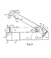
- a feed and drive mechanism generally referred to by the reference numeral 10.
- the mechanism supports paper supply rolls 12 and 14.
- the supply roll 12 holds strip paper for receipts, as in a cash register.
- the supply roll 14 holds strip paper for a permanent journal record, as in a cash register, and is fed to a take-up reel 16 for permanent storage. Paper from each of these rolls 12 and 14 is fed to the line of contact or nip 17 formed between a drive roll 18 rotatively supported by pivots 19 and a pressure roll 20.
- the drive roll 18 and the pressure roll 20 may he each a single unit for the entire drive mechanism or longitudinally split so as to provide a separate drive and pressure roll for each of the paper tapes 12 and 14.
- journal roll 18 and pressure roll 20 When certain information which is printed on the receipt paper is omitted from the journal roll, such as the store name and address, it becomes desirable to drive each tape separately, accounting for the fewer lines appearing on the journal tape.
- the amount of paper feed per transaction is optimized.
- the drive roll and pressure roll, the platen, and the inked ribbon are all secured or guided relative to the frame at fixed locations. Inserting a new paper tape into such machines requires guiding the paper tape into the nip between the drive roll and pressure roll and causing the rolls to rotate in order to draw the paper tape therethrough.
- a narrow gap of typically .020 inch exists between the inked ribbon and the platen through which the paper tape must be threaded. The task is further complicated by the fact that the .020 inch gap is often situated in the machine mechanism so as to be obscured from normal view.
- the pressure rolls 20 are carried on arms 22 which are mounted to the machine by pivots 38.
- a printing platen 26 is also attached to the arms 22 and provides a flat print area 28 on its lower surface.
- a saw tooth tear bar 32 is attached to the frame 31 and a backing plate 30 attached to the platen 26 is spaced from the tear bar 32 to form a tear bar slot 33.
- the pivots 38 by which the arms 22 are rotatively attached to the machine frame are located in elongated slots 40.
- the arms 22 are biased in a raised position by tension springs 44. In this raised position, the pressure roll 20 is spaced from the drive roll 18 to create a gap therebetween, the print area 28 of the platen is spaced from the inked ribbon 46, and the backing plate 30 is removed from behind the tear bar 32.
- Hold-down clips 34 are mounted on the ends of the arm 22 and are selectively engagable with a hold-down rod 36 to position the pressure roll 20 and the printing platen 26 in operative position, and to create the tear bar slot 33.
- the tension springs 44 draw the pivots 38 to the bottom of the elongated slots 40 and rotate the arms 22 and the platen 26 to a raised position.
- the pressure roll 20 is spaced from the drive roll 18 creating a large opening through which the paper tape is easily passed.
- a large non-printable gap 50 is formed between the inked ribbon 46 and the print area 28 of the printing platen 26. This gap allows the paper tape to be placed on top of the inked ribbon and separately threaded into position relative to the saw-toothed cutter 32, or the top surface of the platen 26, as the case may be.
- the tear bar slot 33 is opened up whereby the paper tape may be laid across the top of the tear bar 32.
- the lowered arms 22 also position the print area 28 of the platen the required .020 inch from the inked ribbon 46 so that printing may take place, and the placement of the backing plate 30 behind the tear bar 32 creates the tear bar slot 33 in which the paper tape is automatically captured.
Landscapes
- Handling Of Sheets (AREA)
- Handling Of Continuous Sheets Of Paper (AREA)
- Advancing Webs (AREA)
- Replacement Of Web Rolls (AREA)
Applications Claiming Priority (2)
| Application Number | Priority Date | Filing Date | Title |
|---|---|---|---|
| US06/498,400 US4507003A (en) | 1983-05-26 | 1983-05-26 | Paper tape feed and drive mechanism |
| US498400 | 1983-05-26 |
Publications (1)
| Publication Number | Publication Date |
|---|---|
| EP0127144A2 true EP0127144A2 (de) | 1984-12-05 |
Family
ID=23980932
Family Applications (1)
| Application Number | Title | Priority Date | Filing Date |
|---|---|---|---|
| EP84105949A Withdrawn EP0127144A2 (de) | 1983-05-26 | 1984-05-24 | Papierstreifenvorschub- und Antriebsmechanismus |
Country Status (3)
| Country | Link |
|---|---|
| US (1) | US4507003A (de) |
| EP (1) | EP0127144A2 (de) |
| JP (1) | JPS602556A (de) |
Cited By (5)
| Publication number | Priority date | Publication date | Assignee | Title |
|---|---|---|---|---|
| EP0189124A1 (de) * | 1985-01-25 | 1986-07-30 | Siemens Aktiengesellschaft | Belegverarbeitungseinrichtung für aus einer querperforierten Endlospapierbahn abtrennbare Einzelbelege |
| WO1990012374A1 (de) * | 1989-04-05 | 1990-10-18 | Siemens Nixdorf Informationssysteme Aktiengesellschaft | Teilbare papierteilereinrichtung für vorgefaltetes endlospapier in einer nichtmechanischen druckeinrichtung |
| WO2002026505A1 (de) * | 2000-09-29 | 2002-04-04 | Wincor Nixdorf Gmbh & Co. Kg | Journaldrucker mit schwenkbarer aufwickelanordnung |
| CN104015221A (zh) * | 2014-05-16 | 2014-09-03 | 夏云美 | 一种餐巾纸切纸机的纸卷的引导装置 |
| CN112408044A (zh) * | 2020-10-19 | 2021-02-26 | 浙江雨濠智能设备有限公司 | 一种烫片机 |
Families Citing this family (6)
| Publication number | Priority date | Publication date | Assignee | Title |
|---|---|---|---|---|
| JPH082676B2 (ja) * | 1985-10-23 | 1996-01-17 | 株式会社日立製作所 | プリンタ |
| US5030025A (en) * | 1989-02-01 | 1991-07-09 | Texas Instruments Incorporated | Printer having disengageable idler roller assembly |
| JPH04101187U (ja) * | 1991-02-07 | 1992-09-01 | 株式会社オリムピツク | 宅配物収納ロツカー用受領紙発行機 |
| FR2720331B1 (fr) * | 1994-05-27 | 1996-09-06 | Ier | Imprimerie à guide mobile pour le support à imprimer. |
| FR2723548B1 (fr) * | 1994-08-12 | 1996-10-18 | Axiohm | Dispositif d'impression d'un support en bande issu d'un rouleau |
| JP6534588B2 (ja) * | 2015-09-10 | 2019-06-26 | 富士通コンポーネント株式会社 | プリンタ装置 |
Family Cites Families (7)
| Publication number | Priority date | Publication date | Assignee | Title |
|---|---|---|---|---|
| US3151546A (en) * | 1964-10-06 | Calculating machine | ||
| US579676A (en) * | 1897-03-30 | graham | ||
| GB704952A (en) * | 1950-06-06 | 1954-03-03 | Powers Samas Account Mach Ltd | Improvements in or relating to apparatus for feeding webs of paper to statistical machines |
| US3421612A (en) * | 1965-08-30 | 1969-01-14 | Sperry Rand Corp | Lister attachment for high speed web printers |
| US3822773A (en) * | 1972-12-08 | 1974-07-09 | Avery Products Corp | Embossing tool with controlled spacing |
| US3837461A (en) * | 1973-03-13 | 1974-09-24 | Singer Co | Print station for a matrix printer |
| DE3266349D1 (en) * | 1981-06-19 | 1985-10-24 | Tokyo Electric Co Ltd | Paper feeding device, e.g. for an electronic cash register |
-
1983
- 1983-05-26 US US06/498,400 patent/US4507003A/en not_active Expired - Fee Related
-
1984
- 1984-05-21 JP JP59100711A patent/JPS602556A/ja active Pending
- 1984-05-24 EP EP84105949A patent/EP0127144A2/de not_active Withdrawn
Cited By (8)
| Publication number | Priority date | Publication date | Assignee | Title |
|---|---|---|---|---|
| EP0189124A1 (de) * | 1985-01-25 | 1986-07-30 | Siemens Aktiengesellschaft | Belegverarbeitungseinrichtung für aus einer querperforierten Endlospapierbahn abtrennbare Einzelbelege |
| US4729681A (en) * | 1985-01-25 | 1988-03-08 | Siemens Aktiengesellschaft | Document processing device for single documents separable from a cross-perforated continuous form web |
| WO1990012374A1 (de) * | 1989-04-05 | 1990-10-18 | Siemens Nixdorf Informationssysteme Aktiengesellschaft | Teilbare papierteilereinrichtung für vorgefaltetes endlospapier in einer nichtmechanischen druckeinrichtung |
| US5358346A (en) * | 1989-04-05 | 1994-10-25 | Siemens Nixdorf Informationssysteme Ag | Paper-separating device for prefolded continuous paper in a printing device |
| WO2002026505A1 (de) * | 2000-09-29 | 2002-04-04 | Wincor Nixdorf Gmbh & Co. Kg | Journaldrucker mit schwenkbarer aufwickelanordnung |
| CN104015221A (zh) * | 2014-05-16 | 2014-09-03 | 夏云美 | 一种餐巾纸切纸机的纸卷的引导装置 |
| CN112408044A (zh) * | 2020-10-19 | 2021-02-26 | 浙江雨濠智能设备有限公司 | 一种烫片机 |
| CN112408044B (zh) * | 2020-10-19 | 2022-06-17 | 浙江雨濠智能设备有限公司 | 一种烫片机 |
Also Published As
| Publication number | Publication date |
|---|---|
| JPS602556A (ja) | 1985-01-08 |
| US4507003A (en) | 1985-03-26 |
Similar Documents
| Publication | Publication Date | Title |
|---|---|---|
| US4229113A (en) | Shared document feed station | |
| US6296405B1 (en) | Duplex check printer using a print mechanism pivoted between document paths | |
| US4227819A (en) | Printer platen | |
| US4507003A (en) | Paper tape feed and drive mechanism | |
| US5943085A (en) | Image recording device having detachable web roll cassette | |
| US4589784A (en) | Point of sale printer | |
| US4439051A (en) | Single printing station, multiple record member feeding mechanism | |
| US5000598A (en) | Guide mechanism for dot matrix printer | |
| US4496256A (en) | Impact printing apparatus | |
| US4149458A (en) | Receipt printer for cash registers and the like | |
| US4141660A (en) | Printer for data-processing machine having single operator station | |
| US5672015A (en) | Apparatus and method for printing | |
| EP0127145A1 (de) | Doppelkopf-Dreistationendrucker | |
| US2246969A (en) | Typewriting machine | |
| US4961657A (en) | Record media drive mechanism for dot matrix printer | |
| JPH0393570A (ja) | 両面印字装置 | |
| JPS60264274A (ja) | タイプライタ等のインクリボンカセツト | |
| JP4009364B2 (ja) | 金銭登録機 | |
| JPH0318197Y2 (de) | ||
| JPH10138584A (ja) | プリンタ | |
| JPH056135Y2 (de) | ||
| JP3031494B2 (ja) | 預金通帳記帳用プリンタ | |
| JPS6353075A (ja) | 紙送り装置 | |
| JPH07178990A (ja) | 通帳記帳方法 | |
| JPS646033B2 (de) |
Legal Events
| Date | Code | Title | Description |
|---|---|---|---|
| PUAI | Public reference made under article 153(3) epc to a published international application that has entered the european phase |
Free format text: ORIGINAL CODE: 0009012 |
|
| AK | Designated contracting states |
Designated state(s): DE FR SE |
|
| STAA | Information on the status of an ep patent application or granted ep patent |
Free format text: STATUS: THE APPLICATION HAS BEEN WITHDRAWN |
|
| 18W | Application withdrawn |
Withdrawal date: 19850228 |
|
| RIN1 | Information on inventor provided before grant (corrected) |
Inventor name: WINCENT, KARL TOMMY |