EP0189124A1 - Belegverarbeitungseinrichtung für aus einer querperforierten Endlospapierbahn abtrennbare Einzelbelege - Google Patents
Belegverarbeitungseinrichtung für aus einer querperforierten Endlospapierbahn abtrennbare Einzelbelege Download PDFInfo
- Publication number
- EP0189124A1 EP0189124A1 EP86100518A EP86100518A EP0189124A1 EP 0189124 A1 EP0189124 A1 EP 0189124A1 EP 86100518 A EP86100518 A EP 86100518A EP 86100518 A EP86100518 A EP 86100518A EP 0189124 A1 EP0189124 A1 EP 0189124A1
- Authority
- EP
- European Patent Office
- Prior art keywords
- paper
- processing device
- document processing
- frame
- frame part
- Prior art date
- Legal status (The legal status is an assumption and is not a legal conclusion. Google has not performed a legal analysis and makes no representation as to the accuracy of the status listed.)
- Granted
Links
- 238000013475 authorization Methods 0.000 claims description 3
- 230000006835 compression Effects 0.000 claims description 2
- 238000007906 compression Methods 0.000 claims description 2
- 230000004888 barrier function Effects 0.000 description 4
- 239000011324 bead Substances 0.000 description 4
- 238000012423 maintenance Methods 0.000 description 3
- 230000000903 blocking effect Effects 0.000 description 2
- 238000011161 development Methods 0.000 description 1
- 230000018109 developmental process Effects 0.000 description 1
- 230000005484 gravity Effects 0.000 description 1
- 230000002093 peripheral effect Effects 0.000 description 1
- 238000000926 separation method Methods 0.000 description 1
- 238000011179 visual inspection Methods 0.000 description 1
Images
Classifications
-
- B—PERFORMING OPERATIONS; TRANSPORTING
- B41—PRINTING; LINING MACHINES; TYPEWRITERS; STAMPS
- B41J—TYPEWRITERS; SELECTIVE PRINTING MECHANISMS, i.e. MECHANISMS PRINTING OTHERWISE THAN FROM A FORME; CORRECTION OF TYPOGRAPHICAL ERRORS
- B41J29/00—Details of, or accessories for, typewriters or selective printing mechanisms not otherwise provided for
- B41J29/12—Guards, shields or dust excluders
- B41J29/13—Cases or covers
-
- B—PERFORMING OPERATIONS; TRANSPORTING
- B41—PRINTING; LINING MACHINES; TYPEWRITERS; STAMPS
- B41J—TYPEWRITERS; SELECTIVE PRINTING MECHANISMS, i.e. MECHANISMS PRINTING OTHERWISE THAN FROM A FORME; CORRECTION OF TYPOGRAPHICAL ERRORS
- B41J11/00—Devices or arrangements of selective printing mechanisms, e.g. ink-jet printers or thermal printers, for supporting or handling copy material in sheet or web form
- B41J11/58—Supply holders for sheets or fan-folded webs, e.g. shelves, tables, scrolls, pile holders
-
- B—PERFORMING OPERATIONS; TRANSPORTING
- B41—PRINTING; LINING MACHINES; TYPEWRITERS; STAMPS
- B41J—TYPEWRITERS; SELECTIVE PRINTING MECHANISMS, i.e. MECHANISMS PRINTING OTHERWISE THAN FROM A FORME; CORRECTION OF TYPOGRAPHICAL ERRORS
- B41J15/00—Devices or arrangements of selective printing mechanisms, e.g. ink-jet printers or thermal printers, specially adapted for supporting or handling copy material in continuous form, e.g. webs
- B41J15/04—Supporting, feeding, or guiding devices; Mountings for web rolls or spindles
Definitions
- the invention relates to a document processing device according to the preamble of patent claim 1.
- Such document processing devices are used, for example, in banks and savings banks as so-called account statement printers. They are self-service devices that the respective user, provided he has an authorization card, e.g. a magnetic stripe-coded check card is an opportunity to have the latest account movements and thus the current account balance printed out on one or more receipts. These devices should be placed as close as possible to the wall in the switch hall and fastened there, but as a result they will not be easily accessible from the rear.
- an authorization card e.g. a magnetic stripe-coded check card
- the present invention has for its object to provide a document processing device of the type mentioned that not only the operation by customers but also the maintenance of the device, such as refilling paper, inserting the paper web in the feed device, changing the ribbon or the ink cartridge, and how to troubleshoot a paper jam problem from the front.
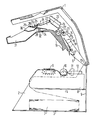
- the device shown in the figure in a sectional view consists of a frame with several functional modules and a housing. From the housing, only the housing cover 1 is visible, while the rear wall and two side walls are not shown for reasons of clarity.
- the frame is made up of two parts and consists of a lower frame part 2 with base 3, intermediate base 4, two side walls (not shown) and a rear housing wall 5 and a pivotable upper frame part 6. Between the base 3 and the intermediate base 4 there is a paper supply space for a continuous paper stack 7 intended. From this paper supply space, which is open towards the front, the paper web runs to a printing device 8 attached to the intermediate floor 4.
- This printing device 8 essentially consists of a feed device, for example, feed caterpillars 9 for the paper web provided with edge perforation, from a platen roller 1 0, a print head 11 and an ink ribbon cassette 12 or an ink cartridge and associated drives and controls.
- On the upper side of the upper frame part 6 there is also an identification reader 14 for a customer-related authorization, credit card or the like, a keyboard 15 for entering a customer-specific code number and a display (not shown).
- Such a device which can be used, for example, as an account statement printer, offers the advantage in terms of maintenance that the paper supply space, the paper guide for the printing device 8 and the feed device with the feed beads 9 are accessible from the front of the device.
- the paper web coming out of the paper supply space initially runs over the horizontally attached feed beads 9, which enable easy paper loading, in the direction of the frame rear wall 5 and after deflection on the platen roller 10 again in the opposite direction back to the output compartment on the front of the device.
- the upper part of the paper guide in the area of the feed caterpillars 9 and the feed channel into the platen roller 10 consists of guide profiles 16 provided on the underside of the pivotable frame upper part 6. In this way, the paper web to be clamped in can be easily carried out without having to be inserted through any guide slots be placed on the feed caterpillars 9 from above.
- the frame upper part 6 and the housing cover 1 fastened to the same pivot axis 13 are folded down and locked with the frame lower part 2.
- the housing cover 1 which is held by a locking mechanism, the function of the device can be checked and any paper jam that may be present can be eliminated will.
- the upper frame part 6 must also be swung up. This is done after releasing a lock with the aid of a compression spring clamped between lower frame part 2 and upper frame part 6, for example a gas spring (not shown).
- the frame upper part 6 is folded down again against the pressure of the gas spring and the housing document 1.
- the device can now be started, the paper automatically being fed to the platen roller 10 and is labeled using printhead 11 and ribbon.
- a light barrier 17 provided after the platen roller 10 scans the leading edge of the paper and thus serves for the automatic adjustment of the printed image.
- the platen 1 0 is drivingly coupled to the paper feed mechanism and pushes the paper over the intended in the frame upper part 6 separator 18 with associated paper guide 19 to a tear roller pair 20, 21.
- the distance between the separator 18 and tear roller pair 20, 21 corresponding to the Receipt or form catches which is predetermined by the respective transverse perforations in the continuous paper web.
- the peripheral speed of the pair of tearing rollers 20, 21 is chosen to be greater than that of the platen roller 10, so that the paper web, as soon as it gets between the pair of tearing rollers 20, 2 1 , due to the counterhold by the platen roller 10 and feed caterpillar 9 a tensile force is exerted.
- This tensile force, supported by the separating device 18, causes the paper web to tear at the transverse perforation.
- a double cone is provided as the separating device 18 or tear aid, which projects with its largest diameter into the center of the paper web and consequently tears the perforation from the center towards both sides
- the resulting single document is then transported by the pair of tearing rollers 20, 21 into a collecting compartment 22.
- One of the two upper paper guide elements 23, 24 provided in the collecting compartment 22 can be opened and thus gives the possibility of eliminating a possible paper jam.
- two blocking fingers 25 are provided which prevent the individual receipts from slipping out into a subsequent output compartment 26 until all the individual receipts intended for the respective user, for example account statements, have been printed and stacked in the collecting compartment 22.
- the light barrier 27 controls the transport through the tear rollers 20, 21 and the separation or separating the documents or forms.
- the pivoting of the rocker is blocked by the toggle lever extended in the delivery position. This prevents the rocker from swinging back from the outside and thus prevents access to the storage compartment.
- the toggle lever is held in an extended position by a return spring and a stop attached to the upper frame part 6. With the help of an electromagnet, it is finally pivoted back into its original position.
- the light barrier 3 4 provided below the rocker on the upper frame part 6 is directed at the paper guide immediately in front of the feed beads 9 and reports a possible end of the paper web to the control of the device.
Landscapes
- Handling Of Sheets (AREA)
- Exposure Or Original Feeding In Electrophotography (AREA)
- Accessory Devices And Overall Control Thereof (AREA)
- Preliminary Treatment Of Fibers (AREA)
- Folding Of Thin Sheet-Like Materials, Special Discharging Devices, And Others (AREA)
- Handling Of Continuous Sheets Of Paper (AREA)
Abstract
Description
- Die Erfindung betrifft eine Belegverarbeitungseinrichtung nach dem Oberbegriff des Patentanspruchs 1.
- Derartige Belegverarbeitungseinrichtungen werden beispielsweise bei Banken und Sparkassen als sogenannte Kontoauszugsdrucker verwendet. Es sind Selbstbedienungsgeräte, die dem jeweiligen Benutzer, sofern er in Besitz einer Berechtigungskarte, z.B. einer magnetstreifencodierten Scheckkarte ist, die Gelegenheit geben, sich die letzten Kontobewegungen und damit den jeweils aktuellen Kontostand auf einem oder mehreren Belegen ausdrucken zu lassen. Diese Geräte sollen in der Schalterhalle möglichst dicht an der Wand aufgestellt und dort befestigt werden, was jedoch zur Folge hat, daß sie dann von der Rückseite aus nicht ohne weiteres zugänglich sind.
- Der vorliegenden Erfindung liegt die Aufgabe zugrunde, eine Belegverarbeitungseinrichtung der eingangs genannten Art so auszubilden, daß nicht nur die Bedienung durch Kunden sondern auch die Wartung des Gerätes, beispielsweise das Nachfüllen von Papier, das Einlegen der Papierbahn in die Vorschubeinrichtung, das Auswechseln des Farbbandes oder der Tintenpatrone sowie die Beseitigung einer durch einen Papierstau verursachten Betriebsstörung von der Vorderseite aus erfolgen kann.
- Die Lösung dieser Aufgabe ergibt sich erfindungsgemäß durch die kenzeichnenden Merkmale des Patentanspruchs 1
- Vorteilhafte Weiterbildungen der Erfindung ergeben sich aus den Merkmalen der Unteransprüche.
- Im folgenden wird ein Ausführungsbeispiel der Erfindung anhand der Zeichnung näher enäutert.
- Das in der Figur in einem Schnittbild dargestellte Gerät besteht aus einem Gestell mit mehreren Funktionsbaugruppen und einem Gehäuse. Vom Gehäuse ist nur der Gehäusedeckel 1 sichtbar, während die Rückwand und zwei Seitenwände aus Gründen der Übersichtlichkeit nicht dargestellt sind. Das Gestell ist zweiteilig ausgebildet und besteht aus einem Gestellunterteil 2 mit Boden 3, Zwischenboden 4, zwei Seitenwänden (nicht dargestellt) und einer Gehäuserückwand 5 sowie aus einem schwenkbaren Gestelloberteil 6. Zwischen dem Boden 3 und dem Zwischenboden 4 ist ein Papiervorratsraum für einen Endlospapierstapel 7 vorgesehen. Von diesem Papiervorratsraum, der zur Vorderseite hin offen ist, verfäuft die Papierbahn zu einer auf dem Zwischenboden 4 befestigten Druckvorrichtung 8. Diese Druckvorrichtung 8 besteht im wesentlichen aus einer Vorschubeinrichtung, beispielsweise aus Vorschubraupen 9 für die mit einer Randlochung versehene Papierbahn, aus einer Schreibwalze 10, einem Druckkopf 11 und einer Farbbandkassette 12 bzw.einer Tintenpatrone sowie dazugehörigen Antrieben und Steuerungen. Das über eine Schwenkachse 13 an der Gestellrückwand 5 hochklappbare Gestelloberteil 6 enthält die der Druckvorrichtung 8 nachgeschalteten Papierverarbeitungsstationen, wie Trennvorrichtung, Sammel-, Ausgabe- und Ablagefach. An der Oberseite des Gestelloberteiles 6 sind ferner ein Ausweisleser 14 für einen kundenbezogenen Berechtigungsausweis, Scheckkarte oder dergleichen, eine Tastatur 15 zur Eingabe einer kundenspezifischen Kodenummer sowie ein nicht dargestelltes Display befestigt.
- Ein derartiges, beispielsweise als Kontoauszugsdrucker verwendbares Gerät bietet in Bezug auf die Wartung den Vorteil, daß der Papiervorratsraum, die Papierführung für die Druckeinrichtung 8 und die Vorschubeinrichtung mit den Vorschubraupen 9 von der Gerätevorderseite zugänglich sind. Die aus dem Papiervorratsraum kommende Papierbahn verläuft zunächst über die waagrecht angebrachten Vorschubraupen 9, die ein bequemes Papiereinlegen ermöglichen, in Richtung Gestellrückwand 5 und nach Umlenkung an der Schreibwalze 10 wieder in entgegengesetzter Richtung zurück zum Ausgabefach an der Vorderseite des Gerätes. Der obere Teil der Papierführung im Bereich der Vorschubraupen 9 und des Einschleuskanals in die Schreibwalze 10 besteht aus an der Unterseite des - schwenkbaren Gestelloberteiles 6 vorgesehenen Führungsprofilen 16. Auf diese Weise kann die einzuspannende Papierbahn, ohne daß sie durch irgendwelche Führungsschlitze gesteckt werden müßte, bequem von oben auf die Vorschubraupen 9 aufgelegt werden.
- Für den Betrieb des Gerätes sind das Gestelloberteil 6 und der an derselben Schwenkachse 13 befestigte Gehäusedeckel 1 heruntergeklappt und mit dem Gestellunterteil 2 verriegelt Durch Hochklappen des Gehäusedeckels 1, der durch einen Rastmechanismus gehalten wird, kann die Funktion des Gerätes überprüft und ein eventuell vorhandener Papierstau beseitigt werden. Zum Einlegen des Papiers und zum Farbbandwechsel muß auch das Gestelloberteil 6 hochgeschwenkt werden. Dies geschieht nach Lösen einer Verriegelung mit Hilfe einer zwischen Gestelluntereil 2 und Gestelloberteil 6 eingespannten Druckfeder, beispielsweise einer Gasfeder (nicht dargestellt).
- Sobald ein Endlospapierstapel 7 in den Papiervorratsraum und der Papieranfang mit der Randlochung in die Vorschubraupen 9 eingelegt sind, wird das Gestelloberteil 6 gegen den Druck der Gasfeder sowie der Gehäusedeokel 1 wieder heruntergeklappt Das Gerät kann nun gestartet werden, wobei das Papier automatisch der Schreibwalze 10 zugeführt und mittels Druckkopf 11 und Farbband beschriftet wird. Eine nach der Schreibwalze 10 vorgesehene Lichtschranke 17 tastet die Papiervorderkante ab und dient somit zur selbsttätigen Justierung des Druckbildes. Die Schreibwalze 10 ist antriebsmäßig mit der Papiervorschubeinrichtung gekoppelt und schiebt das Papier über die im Gestelloberteil 6 vorgesehene Trennvorrichtung 18 mit zugehöriger Papierführung 19 zu einem Reißwalzenpaar 20, 21. Der Abstand zwischen Trennvorrichtung 18 und Reißwalzenpaar 20, 21 entspricht der Beleg- bzw. Formularfänge, die durch die jeweiligen Querperforationen in der Endlospapierbahn vorgegeben ist Außerdem ist die Umfangsgeschwindigkeit des Reißwalzenpaares 20, 21 größer gewählt als die der Schreibwalze 10, so daß auf die Papierbahn, sobald sie zwischen das Reißwalzenpaar 20, 21 gelangt, aufgrund der Gegenhaltung durch Schreibwalze 10 und Vorschubraupe 9 eine Zugkraft ausgeübt wird. Diese Zugkraft bewirkt, unterstützt durch die Trennvorrichtung 18 ein Reißen der Papierbahn an der Querperforation. Als Trennvorrichtung 18 oder Reißhilfe ist ein Doppelkegel vorgesehen, der mit seinem größten Durchmesser in die Mitte der Papierbahn hineinragt und demzufolge die Perforation von der Mitte aus nach beiden Seiten hin aufreißt
- Der so entstandene Einzelbeleg wird nun vom Reißwalzenpaar 20, 21 in ein Sammelfach 22 transportiert. Eine der beiden im Sammelfach 22 vorgesehenen oberen Papierführungselemente 23, 24 ist aufklappbar und gibt damit die Möglichkeit, einen eventuellen Papierstau zu beseitigen. Im Sammelfach 22 sind zwei Sperrfinger 25 vorgesehen, die das Herausrutschen der Einzelbelege in ein nachfolgendes Ausgabefach 26 so lange verhindern, bis alle für den jeweiligen Benutzer bestimmten Einzelbelege, beispielsweise Kontoauszüge gedruckt und im Sammetfach 22 gestapelt sind. Die Lichtschranke 27 kontrolliert den Transport durch die Reißwalzen 20, 21 und das Trennen bzw. Vereinzeln der Belege bzw. Formulare. Nach Hochschwenken der Sperrfinger 25 rutschen alle im Sammelfach 22 vorhandenen Belege, beispielsweise Kontoauszüge auf einer als Wippe gelagerten Auflagefläche 28 in das Ausgabefach 26 und werden dort durch zwei Bremsfedem 29 am Herausfallen gehindert. Für die Entnahme durch die Hand des Benutzers ist die Wippe mit einer Griffmulde 30 versehen und das Ausgabefach mit einem Gehäusedurchbruch vergrößert Letzterer ermöglicht auch eine Sichtkontrolle auf das Ausgabefach 26.
- Bei der Entnahme werden die Belege bzw. Kontoauszüge gegen den Widerstand der Bremsfedem 29 von Hand aus dem Ausgabefach 26 gezogen. Für den Fall, daß die Belege nicht rechtzeitig entnommen werden, erfolgt aus Gründen des Datenschutzes ein Weitertransport in ein von außen nicht zugängliches Ablagefach 31. Zu diesem Zweck wird die Wippe über einen Kniehebelmechanismus um die Drehachse 32 geschwenkt, wobei die Belege nach Freigabe durch die Bremsfedern 29 aufgrund der Schwerkraft in das darunterliegende Ablagefach 31 fallen. Von dort können sie nach Öffnen des Gehäusedeckels 1 durch das Wartungspersonal entnommen werden.
- Über die im Ausgabefach 26 vorgesehene Lichtschranke 33 wird das Herausrutschen der Belege in das Ausgabefach 26 nach dem Öffnen der Sperrfinger 25, ferner das Entnehmen der Belege durch den Kunden und - schließlich der Zustand kontrolliert, ob nach Abschwenken der Wippe und Rückkehr in die Ausgangsstellung das Ausgabefach frei von Papier ist.
- Durch den in der Ausgabestellung gestreckten Kniehebel wird das Schwenken der Wippe blockiert. Damit wird das Zurückschwenken der Wippe von außen und damit ein Zugriff in das Ablagefach verhindert. Der Kniehebel wird durch eine Rückholfeder und einen am Gestelloberteil 6 befestigten Anschlag in einer gestreckten Lage gehalten. Mit Hilfe eines Elektromagneten wird er schließlich wieder in seine Ausgangslage zurückgeschwenkt. Die unterhalb der Wippe am Gestelloberteil 6 vorgesehene Lichtschranke 34 ist auf die Papierführung unmittelbar vor den Vorschubraupen 9 gerichtet und meldet ein eventuelles Ende der Papierbahn an die Steuerung des Gerätes.
Claims (7)
Priority Applications (1)
| Application Number | Priority Date | Filing Date | Title |
|---|---|---|---|
| AT86100518T ATE39090T1 (de) | 1985-01-25 | 1986-01-16 | Belegverarbeitungseinrichtung fuer aus einer querperforierten endlospapierbahn abtrennbare einzelbelege. |
Applications Claiming Priority (2)
| Application Number | Priority Date | Filing Date | Title |
|---|---|---|---|
| DE3502529 | 1985-01-25 | ||
| DE3502529 | 1985-01-25 |
Publications (2)
| Publication Number | Publication Date |
|---|---|
| EP0189124A1 true EP0189124A1 (de) | 1986-07-30 |
| EP0189124B1 EP0189124B1 (de) | 1988-12-07 |
Family
ID=6260795
Family Applications (1)
| Application Number | Title | Priority Date | Filing Date |
|---|---|---|---|
| EP86100518A Expired EP0189124B1 (de) | 1985-01-25 | 1986-01-16 | Belegverarbeitungseinrichtung für aus einer querperforierten Endlospapierbahn abtrennbare Einzelbelege |
Country Status (6)
| Country | Link |
|---|---|
| US (1) | US4729681A (de) |
| EP (1) | EP0189124B1 (de) |
| JP (1) | JPS61172765A (de) |
| AT (1) | ATE39090T1 (de) |
| CA (1) | CA1265542A (de) |
| DE (1) | DE3661345D1 (de) |
Cited By (8)
| Publication number | Priority date | Publication date | Assignee | Title |
|---|---|---|---|---|
| EP0238802A1 (de) * | 1986-03-11 | 1987-09-30 | Siemens Nixdorf Informationssysteme Aktiengesellschaft | Schallschutzgehäuse für Drucker |
| US4806036A (en) * | 1985-11-12 | 1989-02-21 | Genicom Corporation | Printer mechanism carried by upper portion of hinged housing |
| WO1990012374A1 (de) * | 1989-04-05 | 1990-10-18 | Siemens Nixdorf Informationssysteme Aktiengesellschaft | Teilbare papierteilereinrichtung für vorgefaltetes endlospapier in einer nichtmechanischen druckeinrichtung |
| EP0433063A1 (de) * | 1989-12-14 | 1991-06-19 | Kabushiki Kaisha Shinsei Industries | Etikettendruckgerät |
| EP0282207B1 (de) * | 1987-03-11 | 1992-05-06 | Hewlett-Packard Company | Staubschutzschild für einen Drucker |
| US5137385A (en) * | 1989-05-15 | 1992-08-11 | Brother Kyogo Kabushiki Kaisha | Printer for use with electronic cash register |
| EP0526803A3 (en) * | 1991-08-03 | 1993-07-28 | Alcatel Sel Aktiengesellschaft | Printer/cutter unit |
| US5492423A (en) * | 1984-04-03 | 1996-02-20 | Traveler's Express Company, Inc. | Method and apparatus for dispensing money orders including means to detect money orders |
Families Citing this family (11)
| Publication number | Priority date | Publication date | Assignee | Title |
|---|---|---|---|---|
| JPH0732066Y2 (ja) * | 1989-03-10 | 1995-07-26 | シチズン時計株式会社 | プリンタの用紙ガイド機構 |
| JPH02286361A (ja) * | 1989-04-28 | 1990-11-26 | Laurel Bank Mach Co Ltd | 手形小切手等の印字装置 |
| US5238317A (en) * | 1989-10-13 | 1993-08-24 | Siemens Aktiengesellschaft | Printer providing a freely accessible printer frame |
| US5028154A (en) * | 1990-06-15 | 1991-07-02 | Mead Data Central, Inc. | Reversible printing station |
| DE4205773C2 (de) * | 1991-10-08 | 2000-05-25 | Tally Computerdrucker Gmbh | Drucker, insbesondere Reisebürodrucker |
| US5516219A (en) * | 1994-08-01 | 1996-05-14 | Lasermaster Corporation | High resolution combination donor/direct thermal printer |
| WO1998043820A1 (en) * | 1997-04-02 | 1998-10-08 | Seiko Epson Corporation | Paper roll loading mechanism for printers |
| ES2260356T3 (es) | 2001-06-25 | 2006-11-01 | Seiko Epson Corporation | Impresora. |
| US7914218B2 (en) | 2006-06-29 | 2011-03-29 | Toshiba Tec Kabushiki Kaisha | Thermal printer and printing device |
| JP2009083447A (ja) * | 2007-10-03 | 2009-04-23 | Seiko Instruments Inc | プリンタおよび発行装置 |
| KR102890856B1 (ko) * | 2025-07-24 | 2025-11-26 | (주)워프비전 | 분리형 차별화 가이드 기반 유연 기판 편집 시스템 |
Citations (4)
| Publication number | Priority date | Publication date | Assignee | Title |
|---|---|---|---|---|
| FR1402910A (fr) * | 1964-03-19 | 1965-06-18 | Bull Sa Machines | Perfectionnements aux dispositions concernant le ruban d'impression dans les machines imprimantes |
| US4348125A (en) * | 1979-08-10 | 1982-09-07 | Copal Company Limited | Paper guide mechanism of printer |
| DE3333537A1 (de) * | 1982-09-16 | 1984-03-22 | Ricoh Co., Ltd., Tokyo | Aufzeichnungseinrichtung |
| EP0127144A2 (de) * | 1983-05-26 | 1984-12-05 | Litton Systems, Inc | Papierstreifenvorschub- und Antriebsmechanismus |
Family Cites Families (12)
| Publication number | Priority date | Publication date | Assignee | Title |
|---|---|---|---|---|
| US3656602A (en) * | 1970-09-09 | 1972-04-18 | Data Printer Corp | Paper hold down and penetration control construction for high speed printers |
| US3937925A (en) * | 1974-06-25 | 1976-02-10 | Ibm Corporation | Modular transaction terminal with microprocessor control |
| JPS57109455A (en) * | 1980-12-26 | 1982-07-07 | Toshiba Corp | Recording device |
| JPS5810276A (ja) * | 1981-07-10 | 1983-01-20 | Toshiba Corp | 伝票発行装置 |
| IT1144422B (it) * | 1981-07-23 | 1986-10-29 | Olivetti & Co Spa | Dispositivo per schermare circuiti elettrici |
| JPS5954587A (ja) * | 1982-09-22 | 1984-03-29 | Canon Inc | 印字装置付き電子機器 |
| US4615280A (en) * | 1983-11-02 | 1986-10-07 | Diebold Incorporated | High security support and enclosure structure for electronic equipment |
| DE3400894C2 (de) * | 1984-01-10 | 1987-01-22 | Mannesmann AG, 4000 Düsseldorf | Formularabtrenneinrichtung für randgelochte Endlosformulare mit Abreißperforation |
| DE3410774C1 (de) * | 1984-03-23 | 1985-04-11 | Hermann 7742 St Georgen Stockburger | Kopiergeraet mit einer Einrichtung zum Registrieren seiner Benutzung |
| JPH0643224B2 (ja) * | 1984-06-20 | 1994-06-08 | 株式会社東芝 | 記録装置 |
| NL8403057A (nl) * | 1984-10-08 | 1986-05-01 | Hadewe Bv | Gecombineerde separatie-, scheidings- en sorteerinrichting voor een meervoudige kettingformulierenbaan. |
| GB2177068A (en) * | 1985-06-26 | 1987-01-14 | Ncr Co | Burster apparatus for continuous forms |
-
1986
- 1986-01-16 DE DE8686100518T patent/DE3661345D1/de not_active Expired
- 1986-01-16 EP EP86100518A patent/EP0189124B1/de not_active Expired
- 1986-01-16 AT AT86100518T patent/ATE39090T1/de active
- 1986-01-22 US US06/820,804 patent/US4729681A/en not_active Expired - Fee Related
- 1986-01-22 JP JP61011807A patent/JPS61172765A/ja active Pending
- 1986-01-23 CA CA000500152A patent/CA1265542A/en not_active Expired - Lifetime
Patent Citations (4)
| Publication number | Priority date | Publication date | Assignee | Title |
|---|---|---|---|---|
| FR1402910A (fr) * | 1964-03-19 | 1965-06-18 | Bull Sa Machines | Perfectionnements aux dispositions concernant le ruban d'impression dans les machines imprimantes |
| US4348125A (en) * | 1979-08-10 | 1982-09-07 | Copal Company Limited | Paper guide mechanism of printer |
| DE3333537A1 (de) * | 1982-09-16 | 1984-03-22 | Ricoh Co., Ltd., Tokyo | Aufzeichnungseinrichtung |
| EP0127144A2 (de) * | 1983-05-26 | 1984-12-05 | Litton Systems, Inc | Papierstreifenvorschub- und Antriebsmechanismus |
Non-Patent Citations (2)
| Title |
|---|
| IBM TECHNICAL DISCLOSURE BULLETIN, Band 17, Nr. 5, Oktober 1974, Seite 1324, Armonk, US; G.R. CHICKANOSKY et al.: "Stay arm mechanism" * |
| PATENTS ABSTRACTS OF JAPAN, Band 8, Nr. 158 (M-311) [1595], 21. Juli 1984; & JP - A - 59 54 587 (CANON K.K.) 29.03.1984 * |
Cited By (12)
| Publication number | Priority date | Publication date | Assignee | Title |
|---|---|---|---|---|
| US5492423A (en) * | 1984-04-03 | 1996-02-20 | Traveler's Express Company, Inc. | Method and apparatus for dispensing money orders including means to detect money orders |
| US5570960A (en) * | 1984-04-03 | 1996-11-05 | Travelers Express Company, Inc. | Apparatus for dispensing money orders |
| US5647677A (en) * | 1984-04-03 | 1997-07-15 | Travelers Express Company, Inc. | Apparatus for dispensing documents having monetary value |
| US5667315A (en) * | 1984-04-03 | 1997-09-16 | Travelers Express Company, Inc. | Method and apparatus for dispensing money orders |
| US5678937A (en) * | 1984-04-03 | 1997-10-21 | Travelers Express Company, Inc. | Apparatus for dispensing a document having monetary value |
| US4806036A (en) * | 1985-11-12 | 1989-02-21 | Genicom Corporation | Printer mechanism carried by upper portion of hinged housing |
| EP0238802A1 (de) * | 1986-03-11 | 1987-09-30 | Siemens Nixdorf Informationssysteme Aktiengesellschaft | Schallschutzgehäuse für Drucker |
| EP0282207B1 (de) * | 1987-03-11 | 1992-05-06 | Hewlett-Packard Company | Staubschutzschild für einen Drucker |
| WO1990012374A1 (de) * | 1989-04-05 | 1990-10-18 | Siemens Nixdorf Informationssysteme Aktiengesellschaft | Teilbare papierteilereinrichtung für vorgefaltetes endlospapier in einer nichtmechanischen druckeinrichtung |
| US5137385A (en) * | 1989-05-15 | 1992-08-11 | Brother Kyogo Kabushiki Kaisha | Printer for use with electronic cash register |
| EP0433063A1 (de) * | 1989-12-14 | 1991-06-19 | Kabushiki Kaisha Shinsei Industries | Etikettendruckgerät |
| EP0526803A3 (en) * | 1991-08-03 | 1993-07-28 | Alcatel Sel Aktiengesellschaft | Printer/cutter unit |
Also Published As
| Publication number | Publication date |
|---|---|
| EP0189124B1 (de) | 1988-12-07 |
| DE3661345D1 (en) | 1989-01-12 |
| US4729681A (en) | 1988-03-08 |
| JPS61172765A (ja) | 1986-08-04 |
| ATE39090T1 (de) | 1988-12-15 |
| CA1265542A (en) | 1990-02-06 |
Similar Documents
| Publication | Publication Date | Title |
|---|---|---|
| EP0189124B1 (de) | Belegverarbeitungseinrichtung für aus einer querperforierten Endlospapierbahn abtrennbare Einzelbelege | |
| DE69528053T2 (de) | Druckmechanismus für bankautomat | |
| EP0009676B1 (de) | Transportvorrichtung für Aufzeichnungsträger in Druckern | |
| DE69017605T2 (de) | Ablagevorrichtung für Briefumschläge und Einzelblätter. | |
| DE60019872T2 (de) | Drucker | |
| DE69530664T2 (de) | Frankiermaschine mit Tintenstrahldrucker | |
| DE69812841T2 (de) | Druckerschneidegerät | |
| DE3118687C2 (de) | ||
| DE69511762T2 (de) | Schneidmechanismus und zugehöriges Druckgerät | |
| DE69534401T2 (de) | Abzugzufördervorrichtung für geldautomaten | |
| DE69511308T2 (de) | Druckvorrichtung und Steuerungsverfahren dafür | |
| US6386445B2 (en) | Medium issuing apparatus using paper roll medium and automatic teller machine using the apparatus | |
| DE69827905T2 (de) | Vorrichtung zum Vereinzeln und Transportieren von Bögen | |
| EP0189105B1 (de) | Ausgabefach für eine Belegverarbeitungseinrichtung | |
| EP0090401A2 (de) | Gehäuseabdeckung für wahlweise mit Endlos- und Einzelpapier betriebene Druckeinrichtungen | |
| DE8501985U1 (de) | Belegverarbeitungseinrichtung für aus einer querperforierten Endlospapierbahn abtrennbare Einzelbelege | |
| EP0472673B1 (de) | Behälter zur aufnahme von wertscheinen in einem wertscheinausgabegerät | |
| DE3545912A1 (de) | Aufzeichnungsgeraet | |
| JP7660450B2 (ja) | プリンタ | |
| EP0199083A2 (de) | Wertscheingeber | |
| JP7551541B2 (ja) | プリンタ | |
| EP0192941B1 (de) | Papierablagevorrichtung für Drucker od. dgl. | |
| DE69904434T2 (de) | Automatische Druckträgerhandhabung | |
| EP0961236A2 (de) | Vorrichtung zum Bedrucken von Postgut | |
| DE69819830T2 (de) | Druckgerät, Verfahren zu seiner Steuerung und Datenspeichermedium |
Legal Events
| Date | Code | Title | Description |
|---|---|---|---|
| PUAI | Public reference made under article 153(3) epc to a published international application that has entered the european phase |
Free format text: ORIGINAL CODE: 0009012 |
|
| AK | Designated contracting states |
Kind code of ref document: A1 Designated state(s): AT BE CH DE FR GB IT LI NL SE |
|
| 17P | Request for examination filed |
Effective date: 19860826 |
|
| 17Q | First examination report despatched |
Effective date: 19880115 |
|
| GRAA | (expected) grant |
Free format text: ORIGINAL CODE: 0009210 |
|
| AK | Designated contracting states |
Kind code of ref document: B1 Designated state(s): AT BE CH DE FR GB IT LI NL SE |
|
| REF | Corresponds to: |
Ref document number: 39090 Country of ref document: AT Date of ref document: 19881215 Kind code of ref document: T |
|
| REF | Corresponds to: |
Ref document number: 3661345 Country of ref document: DE Date of ref document: 19890112 |
|
| ET | Fr: translation filed | ||
| ITF | It: translation for a ep patent filed | ||
| GBT | Gb: translation of ep patent filed (gb section 77(6)(a)/1977) | ||
| PLBE | No opposition filed within time limit |
Free format text: ORIGINAL CODE: 0009261 |
|
| STAA | Information on the status of an ep patent application or granted ep patent |
Free format text: STATUS: NO OPPOSITION FILED WITHIN TIME LIMIT |
|
| 26N | No opposition filed | ||
| ITTA | It: last paid annual fee | ||
| PGFP | Annual fee paid to national office [announced via postgrant information from national office to epo] |
Ref country code: GB Payment date: 19911217 Year of fee payment: 7 |
|
| PGFP | Annual fee paid to national office [announced via postgrant information from national office to epo] |
Ref country code: AT Payment date: 19911231 Year of fee payment: 7 |
|
| PGFP | Annual fee paid to national office [announced via postgrant information from national office to epo] |
Ref country code: FR Payment date: 19920122 Year of fee payment: 7 Ref country code: BE Payment date: 19920122 Year of fee payment: 7 |
|
| PGFP | Annual fee paid to national office [announced via postgrant information from national office to epo] |
Ref country code: SE Payment date: 19920127 Year of fee payment: 7 |
|
| PGFP | Annual fee paid to national office [announced via postgrant information from national office to epo] |
Ref country code: NL Payment date: 19920131 Year of fee payment: 7 |
|
| PGFP | Annual fee paid to national office [announced via postgrant information from national office to epo] |
Ref country code: DE Payment date: 19920325 Year of fee payment: 7 |
|
| PGFP | Annual fee paid to national office [announced via postgrant information from national office to epo] |
Ref country code: CH Payment date: 19920422 Year of fee payment: 7 |
|
| PG25 | Lapsed in a contracting state [announced via postgrant information from national office to epo] |
Ref country code: GB Effective date: 19930116 Ref country code: AT Effective date: 19930116 |
|
| PG25 | Lapsed in a contracting state [announced via postgrant information from national office to epo] |
Ref country code: SE Effective date: 19930117 |
|
| PG25 | Lapsed in a contracting state [announced via postgrant information from national office to epo] |
Ref country code: LI Effective date: 19930131 Ref country code: CH Effective date: 19930131 Ref country code: BE Effective date: 19930131 |
|
| BERE | Be: lapsed |
Owner name: SIEMENS A.G. BERLIN UND MUNCHEN Effective date: 19930131 |
|
| PG25 | Lapsed in a contracting state [announced via postgrant information from national office to epo] |
Ref country code: NL Effective date: 19930801 |
|
| GBPC | Gb: european patent ceased through non-payment of renewal fee |
Effective date: 19930116 |
|
| NLV4 | Nl: lapsed or anulled due to non-payment of the annual fee | ||
| PG25 | Lapsed in a contracting state [announced via postgrant information from national office to epo] |
Ref country code: FR Effective date: 19930930 |
|
| REG | Reference to a national code |
Ref country code: CH Ref legal event code: PL |
|
| PG25 | Lapsed in a contracting state [announced via postgrant information from national office to epo] |
Ref country code: DE Effective date: 19931001 |
|
| REG | Reference to a national code |
Ref country code: FR Ref legal event code: ST |
|
| EUG | Se: european patent has lapsed |
Ref document number: 86100518.9 Effective date: 19930810 |
|
| PG25 | Lapsed in a contracting state [announced via postgrant information from national office to epo] |
Ref country code: IT Free format text: LAPSE BECAUSE OF NON-PAYMENT OF DUE FEES;WARNING: LAPSES OF ITALIAN PATENTS WITH EFFECTIVE DATE BEFORE 2007 MAY HAVE OCCURRED AT ANY TIME BEFORE 2007. THE CORRECT EFFECTIVE DATE MAY BE DIFFERENT FROM THE ONE RECORDED. Effective date: 20050116 |