EP0127806A2 - Dispositif pour la perforation des bandes - Google Patents
Dispositif pour la perforation des bandes Download PDFInfo
- Publication number
- EP0127806A2 EP0127806A2 EP84105398A EP84105398A EP0127806A2 EP 0127806 A2 EP0127806 A2 EP 0127806A2 EP 84105398 A EP84105398 A EP 84105398A EP 84105398 A EP84105398 A EP 84105398A EP 0127806 A2 EP0127806 A2 EP 0127806A2
- Authority
- EP
- European Patent Office
- Prior art keywords
- hollow cylinder
- carrier
- male
- tools
- male tool
- Prior art date
- Legal status (The legal status is an assumption and is not a legal conclusion. Google has not performed a legal analysis and makes no representation as to the accuracy of the status listed.)
- Withdrawn
Links
Images


Classifications
-
- B—PERFORMING OPERATIONS; TRANSPORTING
- B26—HAND CUTTING TOOLS; CUTTING; SEVERING
- B26F—PERFORATING; PUNCHING; CUTTING-OUT; STAMPING-OUT; SEVERING BY MEANS OTHER THAN CUTTING
- B26F1/00—Perforating; Punching; Cutting-out; Stamping-out; Apparatus therefor
- B26F1/02—Perforating by punching, e.g. with relatively-reciprocating punch and bed
- B26F1/06—Perforating by punching, e.g. with relatively-reciprocating punch and bed with punching tools moving with the work
- B26F1/10—Roller type punches
-
- B—PERFORMING OPERATIONS; TRANSPORTING
- B26—HAND CUTTING TOOLS; CUTTING; SEVERING
- B26D—CUTTING; DETAILS COMMON TO MACHINES FOR PERFORATING, PUNCHING, CUTTING-OUT, STAMPING-OUT OR SEVERING
- B26D7/00—Details of apparatus for cutting, cutting-out, stamping-out, punching, perforating, or severing by means other than cutting
- B26D7/26—Means for mounting or adjusting the cutting member; Means for adjusting the stroke of the cutting member
- B26D7/2614—Means for mounting the cutting member
-
- B—PERFORMING OPERATIONS; TRANSPORTING
- B26—HAND CUTTING TOOLS; CUTTING; SEVERING
- B26F—PERFORATING; PUNCHING; CUTTING-OUT; STAMPING-OUT; SEVERING BY MEANS OTHER THAN CUTTING
- B26F1/00—Perforating; Punching; Cutting-out; Stamping-out; Apparatus therefor
- B26F1/02—Perforating by punching, e.g. with relatively-reciprocating punch and bed
- B26F1/14—Punching tools; Punching dies
-
- Y—GENERAL TAGGING OF NEW TECHNOLOGICAL DEVELOPMENTS; GENERAL TAGGING OF CROSS-SECTIONAL TECHNOLOGIES SPANNING OVER SEVERAL SECTIONS OF THE IPC; TECHNICAL SUBJECTS COVERED BY FORMER USPC CROSS-REFERENCE ART COLLECTIONS [XRACs] AND DIGESTS
- Y10—TECHNICAL SUBJECTS COVERED BY FORMER USPC
- Y10T—TECHNICAL SUBJECTS COVERED BY FORMER US CLASSIFICATION
- Y10T83/00—Cutting
- Y10T83/465—Cutting motion of tool has component in direction of moving work
- Y10T83/4766—Orbital motion of cutting blade
- Y10T83/4795—Rotary tool
- Y10T83/483—With cooperating rotary cutter or backup
- Y10T83/4836—With radial overlap of the cutting members
-
- Y—GENERAL TAGGING OF NEW TECHNOLOGICAL DEVELOPMENTS; GENERAL TAGGING OF CROSS-SECTIONAL TECHNOLOGIES SPANNING OVER SEVERAL SECTIONS OF THE IPC; TECHNICAL SUBJECTS COVERED BY FORMER USPC CROSS-REFERENCE ART COLLECTIONS [XRACs] AND DIGESTS
- Y10—TECHNICAL SUBJECTS COVERED BY FORMER USPC
- Y10T—TECHNICAL SUBJECTS COVERED BY FORMER US CLASSIFICATION
- Y10T83/00—Cutting
- Y10T83/929—Tool or tool with support
- Y10T83/9372—Rotatable type
- Y10T83/9387—Punching tool
- Y10T83/9389—Shear type
-
- Y—GENERAL TAGGING OF NEW TECHNOLOGICAL DEVELOPMENTS; GENERAL TAGGING OF CROSS-SECTIONAL TECHNOLOGIES SPANNING OVER SEVERAL SECTIONS OF THE IPC; TECHNICAL SUBJECTS COVERED BY FORMER USPC CROSS-REFERENCE ART COLLECTIONS [XRACs] AND DIGESTS
- Y10—TECHNICAL SUBJECTS COVERED BY FORMER USPC
- Y10T—TECHNICAL SUBJECTS COVERED BY FORMER US CLASSIFICATION
- Y10T83/00—Cutting
- Y10T83/929—Tool or tool with support
- Y10T83/9411—Cutting couple type
- Y10T83/9423—Punching tool
- Y10T83/9428—Shear-type male tool
-
- Y—GENERAL TAGGING OF NEW TECHNOLOGICAL DEVELOPMENTS; GENERAL TAGGING OF CROSS-SECTIONAL TECHNOLOGIES SPANNING OVER SEVERAL SECTIONS OF THE IPC; TECHNICAL SUBJECTS COVERED BY FORMER USPC CROSS-REFERENCE ART COLLECTIONS [XRACs] AND DIGESTS
- Y10—TECHNICAL SUBJECTS COVERED BY FORMER USPC
- Y10T—TECHNICAL SUBJECTS COVERED BY FORMER US CLASSIFICATION
- Y10T83/00—Cutting
- Y10T83/929—Tool or tool with support
- Y10T83/9411—Cutting couple type
- Y10T83/9423—Punching tool
- Y10T83/9437—Shear-type female tool
-
- Y—GENERAL TAGGING OF NEW TECHNOLOGICAL DEVELOPMENTS; GENERAL TAGGING OF CROSS-SECTIONAL TECHNOLOGIES SPANNING OVER SEVERAL SECTIONS OF THE IPC; TECHNICAL SUBJECTS COVERED BY FORMER USPC CROSS-REFERENCE ART COLLECTIONS [XRACs] AND DIGESTS
- Y10—TECHNICAL SUBJECTS COVERED BY FORMER USPC
- Y10T—TECHNICAL SUBJECTS COVERED BY FORMER US CLASSIFICATION
- Y10T83/00—Cutting
- Y10T83/929—Tool or tool with support
- Y10T83/9457—Joint or connection
- Y10T83/9464—For rotary tool
Definitions
- the proposed device relates to the perforation of paper, plastic, metal, fabric or the like.
- the openings are used, for example, to lead the materials in question through processing machines.
- edge perforations for form webs with round perforations located at the edges of the web are produced in order to pass these webs through fast printers or the like in a later processing operation.
- Other perforations such as filing perforations, are worked into the material to be processed in other places; these perforations can also be circular.
- they have a different shape, since this shape depends, for example, on the later filing of the finished product in a file folder or the like. Beyond that other applications are conceivable for which sheet-like or sheet-like materials with openings of any shape can be produced.
- DE-PS 20 29 863 it is also known from DE-PS 20 29 863 to interchangeably store male tools in a corresponding carrier.
- this carrier is designed in such a way that only male tools with the same geometric dimensions can be exchanged for one another.
- the intermediate holder for each male tool consists of an essentially smooth hollow cylinder on the inside and outside, wherein this hollow cylinder has a radial gap extending through its entire axial extent.
- the end of the hollow cylinder when it is mounted radially on the inside on the carrier, be provided on its outer circumference with an annular groove running over the entire circumference or a part of its outer circumference with a flattened portion.
- a clamping spring into the hat and an essentially cylindrical male tool into the hollow cylinder.
- the hollow cylinder can also be fastened to the carrier with a clamping screw, which clamping screw can come to rest against the flattening of the outer circumference of the hollow cylinder and / or can penetrate a slot worked obliquely into the carrier.
- the proposed solution makes it possible to use perforating tools with a wide variety of geometrical shapes, in terms of both the size of the male parts and the design of the cutting edges, in one and the same carrier.
- a wide variety of perforations with a wide variety of shapes can thus be produced using the same rotating, preferably essentially disk-shaped support.
- the constructive solution is simple and cheap, because it consists essentially of simple turned parts, which can be produced inexpensively on a lathe. This is particularly cost-effective in that these parts, at least for the most part, are also manufactured in a continuous process can.
- blunt blades can be quickly replaced with unused ones.
- a shaft 1 is rotatably supported in a known manner in a machine frame, not shown. At least one carrier 2 is fastened on this shaft 1 and rotates with the shaft 1. The shaft 1 is driven for this purpose. On the carrier 2 there are male tools 3 for perforating sheet or sheet materials 4. For this purpose the male tools 3 work together with female tools 5.
- the die tools are fastened on die carriers 6, which in turn are mounted on a shaft 7 are.
- One or more patrices or matrices can be fastened to the carrier 2 and to the die carrier 6 in mutually equal or unequal intervals distributed over the circumference. 1, for example, eight positions for tools are indicated by dash-dotted lines. However, four or twelve or any other number of tools can also be present, for example.
- the shaft 7 rotates like the shaft 1 and rotates synchronously with it. This can be achieved in that gears are fixed on the shafts 1 and 7, which mesh with each other.
- the Patrizenwerkmaschinee 3 are provided either at one end with a cutting edge '8 or at its two ends with cutting edges. 8 and 9 Each of the cutting edges is offset by a throat 10 in front of the body 11 of the male tool. Apart from the throat 10 and possibly the cutting edges, the body 11 has a cylindrical shape and is smooth on its surface.
- the body 11 of the male tool 3 is inserted into an intermediate holder 12.
- the intermediate bracket 12 has the configuration of a thick-walled hollow cylinder with smooth inner and outer lateral surfaces.
- the hollow cylinder 13 is provided with a gap 14 over its entire axial extent. This gap preferably runs in the radial direction of the hollow cylinder 13 and passes through the hollow cylinder 13 over its entire axial extent.
- an annular groove 15 running around its outer circumference is machined at its radially inner end in the assembled state.
- the carrier 2 contains over its circumference at certain intervals arranged holes 16 which the Push the outer ring 17 of the carrier 2 completely in the radial direction.
- obliquely extending slots 18 are penetrated therethrough in such a way that each slot 18 opens into the bore 16 assigned to it.
- Each slot 18 is also assigned a screw 19 which engages in a thread 20 located in the carrier 2. With the help of the screw 19, the width of the slot 18 can be changed and, if necessary, limited by means of a washer or the like inserted into the slot 18.
- a clamping spring 21 made of bent wire can be inserted into the groove 15. As can be seen from FIGS.
- the axial lengths of the male tool 3 and the hollow cylinder 13 are matched to the recesses located on the carrier 2 in such a way that the radially inner end can in each case be supported on one recess.
- this can either be the body 11 of the male tool itself or the second cutting edge 9 located on the male tool.
- the hollow cylinder 13 is pressed against the carrier 2 by means of the spring 21 and is fixed in the radial direction, in particular with respect to centrifugal forces.
- a new male tool 3 is inserted into the carrier 2 in a simple manner in that a suitable hollow cylinder 13 with a gap 14 is first radially inserted into each bore 16 from the outside.
- This hollow cylinder is fixed in its axial position with respect to the carrier 2 by inserting a clamping spring 21 into the groove 15, ie in the radial direction to the carrier 2.
- a suitable male tool 2 is then inserted into the hollow cylinder 13 from the outside in the radial direction until its radially inner end abuts the carrier 2. Then the screw 19 tightened, reducing both the slot 18 and the gap 14. In this way, the male tool 3 is held in the carrier 2 with a strength sufficient for practical use.
- the male tools are simple turned parts, which can be manufactured essentially in a continuous process.
- the intermediate brackets 12, each of which represents a hollow cylinder 13 are essentially turned parts, which, like the male tools 3, can at least for the most part be produced in a continuous process.
- these intermediate brackets 12 with the most varied inner diameters can be used in the same outer diameter.
- These intermediate brackets are very cheap replacement parts due to their construction, so that due to the variability male tools 3 with the most varied outer diameters of the body 11 can be inserted into the bore 16, as long as it is ensured that the outer diameter of the male tool corresponds to the inner diameter of the hollow cylinder 13. It is conceivable that the wall thickness of the hollow cylinder 13 also become zero and thus a suitably designed male tool 3 can be inserted directly into the bore 16.
- the cutting edges 8 can also have other geometric shapes, which of course has the consequence that the individual male tool becomes more expensive than if it were a circular one Has cutting edge.
- the carrier 2 remains same, which means a significant cost saving for the operation of the entire facility. For example, in the event of a change in the machine's production program, the carrier does not have to be removed from the machine in a time-consuming and costly manner and replaced with a new, different type.
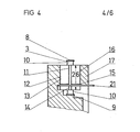
- a flattening 22 is provided on the outer circumference of the hollow cylinder 13 instead of the groove 15.
- a screw 23 can come into contact, which passes through a thread 24 located in the outer ring 17 of the carrier 2.
- the flattened portion 22 extends over the largest possible area 25 of the axial length 26 of the hollow cylinder 13, so that the screw 23 comes to rest against the hollow cylinder 13 radially as far as possible in the assembled state of the device with respect to the carrier 2.
- the screw 23 can clamp the intermediate bracket 12 both in the radial direction with respect to the carrier 2, that is to say press it on one of the recesses of the carrier 2 appearing in steps in FIGS. 4 and 5, and also narrow the gap 14 of the hollow cylindrical intermediate holder 12 and thus the male tool 3 tighten in the intermediate support 12 and thus of the carrier 2 and in the whole perforating device such ⁇ d ß the screw 19 and the slot may be omitted 18th In this case too, only one or both ends of the male tool 3 can be provided with cutting edges.
Landscapes
- Life Sciences & Earth Sciences (AREA)
- Forests & Forestry (AREA)
- Engineering & Computer Science (AREA)
- Mechanical Engineering (AREA)
- Perforating, Stamping-Out Or Severing By Means Other Than Cutting (AREA)
- Folding Of Thin Sheet-Like Materials, Special Discharging Devices, And Others (AREA)
- Moulds For Moulding Plastics Or The Like (AREA)
Applications Claiming Priority (2)
| Application Number | Priority Date | Filing Date | Title |
|---|---|---|---|
| DE3319512A DE3319512C2 (de) | 1983-05-28 | 1983-05-28 | Einrichtung zum Perforieren von bahn- oder bogenförmigen Materialien |
| DE3319512 | 1983-05-28 |
Publications (2)
| Publication Number | Publication Date |
|---|---|
| EP0127806A2 true EP0127806A2 (fr) | 1984-12-12 |
| EP0127806A3 EP0127806A3 (fr) | 1986-08-20 |
Family
ID=6200200
Family Applications (1)
| Application Number | Title | Priority Date | Filing Date |
|---|---|---|---|
| EP84105398A Withdrawn EP0127806A3 (fr) | 1983-05-28 | 1984-05-12 | Dispositif pour la perforation des bandes |
Country Status (3)
| Country | Link |
|---|---|
| US (1) | US4548113A (fr) |
| EP (1) | EP0127806A3 (fr) |
| DE (1) | DE3319512C2 (fr) |
Cited By (2)
| Publication number | Priority date | Publication date | Assignee | Title |
|---|---|---|---|---|
| EP0212846A1 (fr) * | 1985-08-16 | 1987-03-04 | Am International Incorporated | Tambour perforateur pour utilisation dans un perforateur rotatif |
| WO1994008765A1 (fr) * | 1992-10-09 | 1994-04-28 | Maschinenfabrik Goebel Gmbh | Dispositif permettant de perforer des materiaux |
Families Citing this family (10)
| Publication number | Priority date | Publication date | Assignee | Title |
|---|---|---|---|---|
| AU556497B1 (en) * | 1985-07-05 | 1986-11-06 | Mitsubishi Jukogyo Kabushiki Kaisha | Mounting means for stamping device |
| DE8817030U1 (de) * | 1988-08-10 | 1991-12-12 | Schober GmbH Werkzeug- und Maschinenbau, 7147 Eberdingen | Rotationsstanzmaschine |
| US4949449A (en) * | 1989-02-23 | 1990-08-21 | Wilson Manufacturing Company | Quick release rotary punch |
| US5386950A (en) * | 1992-06-08 | 1995-02-07 | Abt; Richard | Apparatus and method for preparing individual wound rolls from a slitted web of material |
| US5429573A (en) * | 1993-10-12 | 1995-07-04 | Economy Machine & Tool Company | Die lift tool for rotary punch machine |
| US7249551B1 (en) * | 2004-09-17 | 2007-07-31 | Ray Daniel W | Gasket cutter with changeable and reversible dies and punches |
| CN101745938A (zh) * | 2008-12-12 | 2010-06-23 | 富准精密工业(深圳)有限公司 | 切孔刀模 |
| JP5421087B2 (ja) * | 2009-12-10 | 2014-02-19 | 大同工業株式会社 | パンチユニット |
| WO2012164612A1 (fr) * | 2011-05-31 | 2012-12-06 | パナソニック株式会社 | Procédé de fabrication d'un corps joint, et corps joint |
| JP6300321B2 (ja) * | 2012-08-07 | 2018-03-28 | 株式会社Joled | 接合体の製造方法及び接合体 |
Family Cites Families (20)
| Publication number | Priority date | Publication date | Assignee | Title |
|---|---|---|---|---|
| DE388697C (de) * | 1922-07-02 | 1924-01-29 | Mueller & Montag G M B H | Einspannfutter fuer Fraeser |
| US1649635A (en) * | 1925-08-28 | 1927-11-15 | Rotary Printing Company | Perforating device |
| US2116391A (en) * | 1936-01-04 | 1938-05-03 | Egry Register Co | Quick-setting adjustable punching apparatus |
| US2264134A (en) * | 1940-09-30 | 1941-11-25 | John F Hawley | Punching equipment |
| US2378806A (en) * | 1944-03-06 | 1945-06-19 | Domnic V Stellin | Interchangeable punch and die and retainer for same |
| US2522154A (en) * | 1947-02-24 | 1950-09-12 | Marathon Corp | Method and means for cutting, punching, blanking, and the like |
| US2844378A (en) * | 1957-07-05 | 1958-07-22 | Lawrence V Whistler | Detachable tool fastening means |
| US3106859A (en) * | 1962-08-22 | 1963-10-15 | Hamilton Tool Co | Apparatus for rotarily punching webs of paper |
| US3192810A (en) * | 1962-10-30 | 1965-07-06 | Arvey Corp | Punching mechanism with tool smoothing means |
| US3194095A (en) * | 1962-12-31 | 1965-07-13 | Lloyd P Buck | Punch confett remover |
| GB994539A (en) * | 1963-08-29 | 1965-06-10 | Allegheny Ludlum Steel | Improvements in or relating to die assemblies |
| US3602080A (en) * | 1969-08-06 | 1971-08-31 | Farrell L Sickel | Chad removal means |
| DE2029863C3 (de) * | 1970-06-18 | 1973-10-25 | Maschinenfabrik Goebel Gmbh, 6100 Darmstadt | Perforierwerk zum gleichzeitigen Langs und Querperforieren von Bogen oder Bahnen |
| US3828632A (en) * | 1972-10-24 | 1974-08-13 | Tools And Prod Inc | Rotary punch |
| SE398981B (sv) * | 1976-05-11 | 1978-01-30 | Malmberg Sven Kurt B | Forfarande vid fastsettning och centrering av stansverktyg och anordning for genomforande av forfarandet |
| US4094185A (en) * | 1977-07-05 | 1978-06-13 | Procor Limited | Double-ended heading punch |
| DE7738194U1 (de) * | 1977-12-15 | 1978-04-27 | Maschinenfabrik Goebel Gmbh, 6100 Darmstadt | Perforiereinrichtung |
| DE7826026U1 (de) * | 1978-09-01 | 1980-02-14 | Upat Gmbh & Co, 7830 Emmendingen | Verlege-hilfswerkzeug |
| US4273015A (en) * | 1979-06-04 | 1981-06-16 | Johnson Donald R | Dome head punch |
| US4434690A (en) * | 1982-01-15 | 1984-03-06 | Rapid Ring Co., Inc. | Rotary press punch ring and method of changing punches carried thereby |
-
1983
- 1983-05-28 DE DE3319512A patent/DE3319512C2/de not_active Expired
-
1984
- 1984-05-12 EP EP84105398A patent/EP0127806A3/fr not_active Withdrawn
- 1984-05-29 US US06/614,562 patent/US4548113A/en not_active Expired - Fee Related
Cited By (2)
| Publication number | Priority date | Publication date | Assignee | Title |
|---|---|---|---|---|
| EP0212846A1 (fr) * | 1985-08-16 | 1987-03-04 | Am International Incorporated | Tambour perforateur pour utilisation dans un perforateur rotatif |
| WO1994008765A1 (fr) * | 1992-10-09 | 1994-04-28 | Maschinenfabrik Goebel Gmbh | Dispositif permettant de perforer des materiaux |
Also Published As
| Publication number | Publication date |
|---|---|
| EP0127806A3 (fr) | 1986-08-20 |
| DE3319512A1 (de) | 1984-11-29 |
| DE3319512C2 (de) | 1985-07-25 |
| US4548113A (en) | 1985-10-22 |
Similar Documents
| Publication | Publication Date | Title |
|---|---|---|
| DE3685910T2 (de) | Rotierende schneidvorrichtung fuer papier. | |
| EP0115783B1 (fr) | Cylindre à couteaux pour couper des bandes | |
| DE2461308A1 (de) | Etikettvorratsband und vorrichtung zur herstellung desselben sowie verfahren zur herstellung von hierfuer benoetigten werkzeugen | |
| DE3319512C2 (de) | Einrichtung zum Perforieren von bahn- oder bogenförmigen Materialien | |
| DE2304092A1 (de) | Einrichtung zum laengsschneiden schmaler streifen | |
| DE1453328B2 (fr) | ||
| DE3711824C2 (fr) | ||
| EP0496741B1 (fr) | Cylindre de coupe | |
| EP0196688B1 (fr) | Cylindre à couteaux pour traiter des matériaux en bandes | |
| DE3510276C1 (de) | Perforiermesser | |
| EP0707930B1 (fr) | Barre d'appui pour la lame d'un dispositif de perforation | |
| DE10261968B4 (de) | Verfahren zur Herstellung eines Mitnehmerelements für einen Spanndorn | |
| DE2112092A1 (de) | Werkzeughalter | |
| DE69914949T2 (de) | Verfahren und vorrichtung zum schneiden von fasern in stücke | |
| EP0507916B1 (fr) | Dispositif de support | |
| DE10254332A1 (de) | Falzzylinder | |
| DE3738196C2 (fr) | ||
| DE8315777U1 (de) | Einrichtung zum perforieren von bahn- oder bogenfoermigen materialien | |
| DE711704C (de) | Schneidwalze fuer Rollenschneidmaschinen | |
| DE9213614U1 (de) | Einrichtung zum Perforieren von Material | |
| DE69902005T2 (de) | Abfallausbrechvorrichtung für gestanzte kartonagen | |
| DE9311792U1 (de) | Einrichtung zum Perforieren von Substraten | |
| DE3120382C2 (de) | Einrichtung zum Einarbeiten von Linien in Bahnen | |
| EP0695710A2 (fr) | Arrangement de moyens adhésifs pour des bobines de remplacement en bande de papier | |
| DE2444104C3 (de) | Spannsatz zum kraftschlüssigen Verbinden einer Welle mit einem dazu konzentrisch angeordneten Bauteil |
Legal Events
| Date | Code | Title | Description |
|---|---|---|---|
| PUAI | Public reference made under article 153(3) epc to a published international application that has entered the european phase |
Free format text: ORIGINAL CODE: 0009012 |
|
| AK | Designated contracting states |
Designated state(s): BE CH FR GB IT LI NL |
|
| ITCL | It: translation for ep claims filed |
Representative=s name: BARZANO' E ZANARDO MILANO S.P.A. |
|
| EL | Fr: translation of claims filed | ||
| TCNL | Nl: translation of patent claims filed | ||
| PUAL | Search report despatched |
Free format text: ORIGINAL CODE: 0009013 |
|
| AK | Designated contracting states |
Kind code of ref document: A3 Designated state(s): BE CH FR GB IT LI NL |
|
| STAA | Information on the status of an ep patent application or granted ep patent |
Free format text: STATUS: THE APPLICATION HAS BEEN WITHDRAWN |
|
| 18W | Application withdrawn |
Withdrawal date: 19860909 |
|
| RIN1 | Information on inventor provided before grant (corrected) |
Inventor name: TOEPPERWIEN, BERND, DIPL. ING. Inventor name: KRAUSE, LOTHAR |