EP0496741B1 - Cylindre de coupe - Google Patents
Cylindre de coupe Download PDFInfo
- Publication number
- EP0496741B1 EP0496741B1 EP90914133A EP90914133A EP0496741B1 EP 0496741 B1 EP0496741 B1 EP 0496741B1 EP 90914133 A EP90914133 A EP 90914133A EP 90914133 A EP90914133 A EP 90914133A EP 0496741 B1 EP0496741 B1 EP 0496741B1
- Authority
- EP
- European Patent Office
- Prior art keywords
- cylinder
- cutter
- groove
- pressurized medium
- knife
- Prior art date
- Legal status (The legal status is an assumption and is not a legal conclusion. Google has not performed a legal analysis and makes no representation as to the accuracy of the status listed.)
- Expired - Lifetime
Links
- 238000005520 cutting process Methods 0.000 title abstract description 15
- 239000002184 metal Substances 0.000 claims description 6
- 239000000463 material Substances 0.000 claims description 4
- 239000004744 fabric Substances 0.000 claims description 3
- 239000011888 foil Substances 0.000 claims description 3
- 230000002093 peripheral effect Effects 0.000 claims 1
- 238000004519 manufacturing process Methods 0.000 description 3
- 230000006835 compression Effects 0.000 description 2
- 238000007906 compression Methods 0.000 description 2
- 239000004033 plastic Substances 0.000 description 2
- 206010067482 No adverse event Diseases 0.000 description 1
- 230000004323 axial length Effects 0.000 description 1
- 210000000078 claw Anatomy 0.000 description 1
- 230000001427 coherent effect Effects 0.000 description 1
- 238000010276 construction Methods 0.000 description 1
- 238000006073 displacement reaction Methods 0.000 description 1
- 238000005553 drilling Methods 0.000 description 1
- 235000021189 garnishes Nutrition 0.000 description 1
- 238000000034 method Methods 0.000 description 1
- 239000000123 paper Substances 0.000 description 1
- 238000003825 pressing Methods 0.000 description 1
- 238000007789 sealing Methods 0.000 description 1
Images


Classifications
-
- B—PERFORMING OPERATIONS; TRANSPORTING
- B26—HAND CUTTING TOOLS; CUTTING; SEVERING
- B26D—CUTTING; DETAILS COMMON TO MACHINES FOR PERFORATING, PUNCHING, CUTTING-OUT, STAMPING-OUT OR SEVERING
- B26D7/00—Details of apparatus for cutting, cutting-out, stamping-out, punching, perforating, or severing by means other than cutting
- B26D7/26—Means for mounting or adjusting the cutting member; Means for adjusting the stroke of the cutting member
- B26D7/2614—Means for mounting the cutting member
-
- B—PERFORMING OPERATIONS; TRANSPORTING
- B27—WORKING OR PRESERVING WOOD OR SIMILAR MATERIAL; NAILING OR STAPLING MACHINES IN GENERAL
- B27L—REMOVING BARK OR VESTIGES OF BRANCHES; SPLITTING WOOD; MANUFACTURE OF VENEER, WOODEN STICKS, WOOD SHAVINGS, WOOD FIBRES OR WOOD POWDER
- B27L11/00—Manufacture of wood shavings, chips, powder, or the like; Tools therefor
- B27L11/005—Tools therefor
-
- Y—GENERAL TAGGING OF NEW TECHNOLOGICAL DEVELOPMENTS; GENERAL TAGGING OF CROSS-SECTIONAL TECHNOLOGIES SPANNING OVER SEVERAL SECTIONS OF THE IPC; TECHNICAL SUBJECTS COVERED BY FORMER USPC CROSS-REFERENCE ART COLLECTIONS [XRACs] AND DIGESTS
- Y10—TECHNICAL SUBJECTS COVERED BY FORMER USPC
- Y10T—TECHNICAL SUBJECTS COVERED BY FORMER US CLASSIFICATION
- Y10T83/00—Cutting
- Y10T83/465—Cutting motion of tool has component in direction of moving work
- Y10T83/4766—Orbital motion of cutting blade
- Y10T83/4795—Rotary tool
- Y10T83/483—With cooperating rotary cutter or backup
- Y10T83/4838—With anvil backup
-
- Y—GENERAL TAGGING OF NEW TECHNOLOGICAL DEVELOPMENTS; GENERAL TAGGING OF CROSS-SECTIONAL TECHNOLOGIES SPANNING OVER SEVERAL SECTIONS OF THE IPC; TECHNICAL SUBJECTS COVERED BY FORMER USPC CROSS-REFERENCE ART COLLECTIONS [XRACs] AND DIGESTS
- Y10—TECHNICAL SUBJECTS COVERED BY FORMER USPC
- Y10T—TECHNICAL SUBJECTS COVERED BY FORMER US CLASSIFICATION
- Y10T83/00—Cutting
- Y10T83/929—Tool or tool with support
- Y10T83/9372—Rotatable type
- Y10T83/9396—Shear type
- Y10T83/9399—Cutting edge wholly parallel to axis of rotation
-
- Y—GENERAL TAGGING OF NEW TECHNOLOGICAL DEVELOPMENTS; GENERAL TAGGING OF CROSS-SECTIONAL TECHNOLOGIES SPANNING OVER SEVERAL SECTIONS OF THE IPC; TECHNICAL SUBJECTS COVERED BY FORMER USPC CROSS-REFERENCE ART COLLECTIONS [XRACs] AND DIGESTS
- Y10—TECHNICAL SUBJECTS COVERED BY FORMER USPC
- Y10T—TECHNICAL SUBJECTS COVERED BY FORMER US CLASSIFICATION
- Y10T83/00—Cutting
- Y10T83/929—Tool or tool with support
- Y10T83/9457—Joint or connection
- Y10T83/9464—For rotary tool
Definitions
- the proposed device relates to a knife cylinder for processing paper, plastic or metal foils, fabric or the like.
- Existing web-like material with at least one provided for receiving and fastening a knife arranged essentially parallel to the axis of rotation of the knife cylinder, also parallel to the axis of rotation of the knife cylinder on its circumference, incorporated in the knife cylinder and distributed over the length of each knife arranged pressure points for clamping the respective knife against the knife cylinder by means of several, distributed over the length of each knife, pressing the respective knife against the knife cylinder Pressure medium cylinder and with a channel system rotating with the knife cylinder, connected to the pressure medium cylinders, and for each knife at least one insert arranged between this knife and a pressure medium cylinder assigned to it, wherein the pressure medium cylinders assigned to each groove are arranged both within the groove and essentially in the circumferential direction of the knife cylinder and the pressure medium cylinders are preferably bellows cylinders made of metal.
- Knife cylinders of the type mentioned are used in machines to make incisions in sheet-like materials. These incisions can be made with knives that do not have a continuous cutting edge, so that a Perforation is generated. The knives can also have a continuous cutting edge. This makes it possible to cut sheets of a certain length from an endless web or to lay them down in zigzag-folded stacks.
- the cutting or cutting lines incorporated into the webs are usually directed transversely to the running direction of the web to be processed.
- the knives required for this are usually inserted into a revolving knife cylinder in such a way that knives that have become blunt can be replaced without the entire cylinder having to be removed from the respective processing machine, for example a form printing machine.
- At least one knife is attached to each knife cylinder.
- a plurality of knives for example two, three, six or eight knives, can be arranged in a regularly or irregularly distributed manner on the circumference of the knife cylinder.
- the knives can be effective in the desired manner, they have to be set in relation to the web to be processed or a pressure cylinder interacting with the knife cylinder.
- the knives are usually non-positively attached to the knife cylinders or within the knife cylinders. If the knives have become dull in the course of their use, then they must be exchanged for new knives will.
- an exchange of the knives generally means that both the cutting device, in which the respective knife is installed, and a further machine, for example a form printing machine, possibly cooperating with the cutting device, must be stopped. Stopping the machine inevitably means a loss of production that is as large as the time in which the machine must be stopped. Efforts are therefore made to replace the knives with as little time as possible.
- a device of the aforementioned type has become known, for example, from EP-A 0 196 688, which is why reference is made to this prior publication at this point to support the description of the present patent application.
- the device described here can be structurally simplified even further, resulting in the task for the present patent application of improving the previously known construction in such a way that its handling is further simplified.
- a web 1 made of paper, plastic, metal, foil, fabric or the like runs past a printing cylinder 2 and partially wraps around it. At the same time, the web 1 passes through a nip which is formed by the pressure cylinder 2 and the knife cylinder 3.
- the pressure cylinder 2 and the knife cylinder 3 are rotatably supported in a machine frame 5 with the aid of corresponding bearings 4. At least one of the two cylinders 2 or 3 is driven, but it is also possible for the two cylinders to be connected to one another by gearwheels, toothed belts or the like, so that they can rotate in a fixed phase relative to one another.
- Knives or knife positions 6, 7, 8, 9, 10 and 11 are provided on the knife cylinder 3.
- the knives located at positions 6 to 11 extend essentially in the direction of the geometric axis of the knife cylinder 3 and are fastened in the knife cylinder 3 parallel or slightly inclined to this axis.
- the associated knives can have a continuous cutting edge or a cutting edge interrupted by transverse grooves. In the case in which the knives have a continuous cutting edge, the web 1 is passed through the through the Cylinder 2 and 3 formed nip cut into individual sheets across.
- the knives are divided into several individual cutting edges by grooves running transversely to their cutting edge, then the web 1 is not cut completely transverse to its running direction. Rather, there is a multitude of incisions in the web 1, a bridge-like web remaining between two incisions. In this way, the web 1 is perforated transversely to the direction indicated by the arrow 12. Because of this perforation, it is possible to tear off individual sheets from the web 1 in a later operation. However, it is also possible, for example, for those points at which the web 1 is weakened by transverse perforations to form articulation points in which the web 1 can be folded transversely to its running direction during a later zigzag folding process.
- Fig. 1 shows an example of a knife cylinder 3, on the circumference of six knives are arranged evenly distributed.
- the knife cylinder 3 it is also possible to design the knife cylinder 3 in such a way that one, two, three, four, five, seven, eight or ten knives or another number of knives or even another number of knives are fastened evenly or evenly distributed from one another on its circumference can.
- the number and positions of the knives provided there is also the number of grooves used for fastening the knives in the knife cylinder for each knife.
- each of the grooves contains a side wall 26 which, within the cylinder 3, represents a surface which extends essentially radially to the latter.
- each groove runs perpendicular to the first side wall 26 and the second side wall 27. Each groove thus contains the three surfaces 26, 27 and 28. Each groove is open towards the outside of the knife cylinder 3.
- An insert 29 is inserted into each groove such that the base 30 of the insert 29 bears against the part 28a of the base of the groove.
- Each insert 29 contains at least one bore 31 through which a screw 32 is inserted.
- the bore 31 of the insert 29 preferably has a larger diameter than the outside diameter of the screw 32.
- the screw 32 is screwed into a thread 33, which is incorporated into the knife cylinder 3 such that the geometric axis of the screw 32 is perpendicular to the geometric axes of the pressure medium cylinders 34, 35, 36 and 37, ie also to the base surface 28 of the groove 20 .
- the pressure medium cylinders are preferably bellows cylinders made of metal.
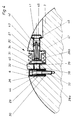
- the knife 6 (groove 20) located in the knife position 6 is pressed against the side wall 26 of the groove 20, for example with the aid of the pressure medium cylinder 34 with the interposition of the insert 29 and a strong, rigid plunger 38.
- the plunger 38 is guided in an opening 39 which is incorporated in a strip-like web 40 fastened in the groove 20.
- This strip-like web can for example be screwed to the base of the groove 20 with the knife cylinder 3 and thus bear against the base surface 28 of the groove 20.
- the web 40 preferably consists of the same component as the knife cylinder 3, ie it is made of the material of the knife cylinder 3 worked out.
- the fact that the pressure medium cylinder 34 is supplied with pressure medium from the channels 41, 42 and 43 creates a force which moves the plunger 38 to the left in FIG. 4, thereby displacing the insert 29 with respect to the screw 32 as far as the difference in the diameter of the Allows bore 31 and outer diameter of the screw 32 and presses the knife 6 from the right in Figure 4 against the knife cylinder 3 and clamped with this non-positively.
- a movement of the insert 29 with respect to the screw 32 is further favored in that a compression spring 44 is inserted between the head of the screw 32 and the insert 29.
- the channels 42 and 43 are incorporated in a screw 45, which in turn is provided with a seal 46.
- the pressure medium cylinder 34 is also provided with a seal 47.
- the web 40 limits the stroke of the cylinder 34 with a corresponding choice of all dimensions, but this has no adverse effects on the tensioning of the knife 6, since the plunger 38 is interposed between the cylinder 34 and the knife 6, which is slightly longer than that in Figure 4 visible width of the web 40, so that enough freedom of movement remains for the pressure medium cylinder to tension or loosen the knife 6.
- the pressure medium cylinder 34 also applies in an analogous manner to all other pressure medium cylinders used in the knife cylinder 3, for example to the other pressure medium cylinders 35, 36 and 37, which are distributed over the length of the knife 6 and the length of all further knives are.
- the pressure medium cylinders 34 and 35 maintain, for example, the distance 48 from one another, the pressure medium cylinders 35 and 36 maintain the distance 49 and the pressure medium cylinders 36 and 37 keep the distance 50.
- the corresponding openings as indicated, for example, by the opening 39, keep distances 51, 52 and 53, such that each opening is arranged concentrically with the respective pressure cylinder.
- the respective plunger, such as the plunger 38, lies in the same line of action.
- each plunger is guided through the strip-like web 40, since each plunger is located in a corresponding recess in this web and is surrounded by the web with sufficient play for its displacement becomes.
- Web 40 thus divides the groove 20 into two partial grooves with the base areas 28a and 28b, the web 40 preferably passing through the entire axial length of the cylinder 3. Its surfaces, shown in FIG. 4 as vertically running edges, run parallel to the side walls 26 and 27 of the groove 20. The same applies analogously to all other grooves of the knife cylinder 3 provided for holding knives.
- the channel 41 is parallel to the respective groove in the knife cylinder 3 incorporated.
Landscapes
- Engineering & Computer Science (AREA)
- Life Sciences & Earth Sciences (AREA)
- Mechanical Engineering (AREA)
- Forests & Forestry (AREA)
- Manufacturing & Machinery (AREA)
- Wood Science & Technology (AREA)
- Perforating, Stamping-Out Or Severing By Means Other Than Cutting (AREA)
- Details Of Cutting Devices (AREA)
- Processing Of Stones Or Stones Resemblance Materials (AREA)
- Polishing Bodies And Polishing Tools (AREA)
Abstract
Claims (6)
- Cylindre de coupe (3) pour le façonnage de produit en bande (1), constitué de papier, de feuilles de matière plastique ou de métal, de tissus ou similaires, comportant au moins une rainure (20 - 25) usinée dans le cylindre porte-couteau (3), située sur la périphérie du cylindre porte-couteau (3) parallèlement à son axe de rotation, et prévue chacune pour recevoir et fixer un couteau (6 - 11) disposé, de même, essentiellement parallèlement à l'axe de rotation du cylindre porte-couteau (3), et comportant des points de mise en pression, répartis sur la longueur de chaque couteau (6 - 11), pour le serrage du couteau correspondant (6) contre le cylindre porte-couteau (3), au moyen de plusieurs vérins à fluide de pression (34 - 37), répartis sur la longueur de chaque couteau (6 - 11) et mettant en serrage chaque couteau (6 - 11) concerné contre le cylindre porte-couteau (3), et comportant un système de canaux (41 - 43) raccordé aux vérins à fluide de pression (34 - 37) et tournant avec le cylindre porte-couteau (3), et comportant, pour chaque couteau (6 - 11), au moins une garniture de calage (29) disposée entre ce couteau (6) et un vérin à fluide de pression (34) qui lui est associé, étant entendu que les vérins à fluide de pression (34 - 37), associés à chaque rainure (20 - 25), sont disposés, d'une part, à l'intérieur de la rainure (20 - 25) et, d'autre part, essentiellement suivant la direction périphérique du cylindre porte-couteau (3) et étant entendu que les vérins à fluide de pression (34 - 37), sont, de préférence, des vérins à soufflets en métal, caractérisé par un dispositif (40) pour limiter la course de chacun des vérins à fluide de pression (34 - 37), sous la forme d'un barreau (40), du genre réglette, fixé à l'intérieur de chaque rainure concernée (20 - 25), et présentant au moins un percement (39), étant entendu que, dans chaque percement (39), entre chaque vérin à fluide de pression (34 - 37) et la garniture (29) de chaque couteau (6 - 11) concerné, un coulisseau (38) est installé et est guidé par le barreau (40) en forme de réglette.
- Dispositif suivant la revendication 1, caractérisé en ce que le barreau (40) en forme de réglette et le cylindre porte-couteau (3) sont réalisés à partir du même constituant.
- Dispositif suivant la revendication 1, caractérisé en ce que les distances réciproques (51 - 53) des percements (39) correspondent aux distances réciproques (48 - 50) de chacun des vérins à fluide de pression (34 - 37) concernés.
- Dispositif suivant la revendication 1, caractérisé en ce que chaque garniture de calage (29) comporte au moins un alésage (31) dirigé perpendiculairement à la surface du fond (28) de chaque rainure (20 - 25).
- Dispositif suivant la revendication 1 et la revendication 4, caractérisé en ce que l'alésage (31) a un diamètre intérieur plus grand que le diamètre extérieur d'une vis (32) qui le traverse.
- Dispositif suivant la revendication 1, caractérisé en ce que l'alimentation en liquide sous pression de chaque vérin à fluide de pression (34 - 37) se fait chaque fois par un canal (41) usiné dans le cylindre porte-couteau (3), parallèlement à chaque rainure (20 - 25) concernée.
Applications Claiming Priority (3)
| Application Number | Priority Date | Filing Date | Title |
|---|---|---|---|
| DE3934525A DE3934525A1 (de) | 1989-10-17 | 1989-10-17 | Messerzylinder |
| DE3934525 | 1989-10-17 | ||
| PCT/DE1990/000760 WO1991005641A1 (fr) | 1989-10-17 | 1990-10-08 | Cylindre de coupe |
Publications (2)
| Publication Number | Publication Date |
|---|---|
| EP0496741A1 EP0496741A1 (fr) | 1992-08-05 |
| EP0496741B1 true EP0496741B1 (fr) | 1994-04-27 |
Family
ID=6391581
Family Applications (1)
| Application Number | Title | Priority Date | Filing Date |
|---|---|---|---|
| EP90914133A Expired - Lifetime EP0496741B1 (fr) | 1989-10-17 | 1990-10-08 | Cylindre de coupe |
Country Status (7)
| Country | Link |
|---|---|
| US (1) | US5159868A (fr) |
| EP (1) | EP0496741B1 (fr) |
| JP (1) | JP2550221B2 (fr) |
| CA (1) | CA2069307C (fr) |
| DE (2) | DE3934525A1 (fr) |
| ES (1) | ES2029987T3 (fr) |
| WO (1) | WO1991005641A1 (fr) |
Families Citing this family (16)
| Publication number | Priority date | Publication date | Assignee | Title |
|---|---|---|---|---|
| DE4139137A1 (de) * | 1991-11-28 | 1993-06-03 | Will E C H Gmbh & Co | Verfahren und vorrichtung zum einstellen der messer eines formatschneiders |
| DE19526507C2 (de) * | 1995-07-20 | 1999-04-08 | Wifag Maschf | Messerzylinder mit verstellbarem Messerbalken |
| US5890410A (en) * | 1997-03-19 | 1999-04-06 | Hinojosa; Domingo | Holding assembly for cutting blade |
| US6244151B1 (en) * | 1998-06-11 | 2001-06-12 | Tamarack Products Inc. | Apparatus for adjusting cutting bar |
| JP2000317885A (ja) * | 1999-05-06 | 2000-11-21 | Sanwa Kako Co Ltd | 合成樹脂発泡体の矩形状の加工方法及び装置 |
| US7454753B2 (en) * | 2001-06-27 | 2008-11-18 | International Business Machines Corporation | Semaphore management subsystem for use with multi-thread processor systems |
| US7007580B2 (en) * | 2002-04-11 | 2006-03-07 | Goss International Americas, Inc. | Apparatus for removably securing a cutting component |
| ATE461795T1 (de) * | 2004-10-08 | 2010-04-15 | Western Printing Mach Co | Matrizenhaltevorrichtung für drehschneidesystem |
| DE102007058816A1 (de) * | 2007-12-05 | 2009-06-10 | Krones Ag | Schneidwerkzeug zum Schneiden von Etiketten |
| DE102007058819A1 (de) * | 2007-12-05 | 2009-06-10 | Krones Ag | Vorrichtung zum Schneiden von Etiketten |
| US10328493B2 (en) | 2013-01-09 | 2019-06-25 | Illinois Tool Works Inc. | Pipe machining apparatuses and methods of operating the same |
| US9399306B2 (en) * | 2013-01-09 | 2016-07-26 | Illinois Tool Works Inc. | Pipe machining apparatuses and methods of operating the same |
| US9278417B2 (en) | 2013-01-09 | 2016-03-08 | Illinois Tool Works Inc. | Pipe machining apparatuses and methods of operating the same |
| US9610636B2 (en) | 2013-01-09 | 2017-04-04 | Illinois Tool Works Inc. | Pipe machining apparatuses and methods of operating the same |
| US10203030B2 (en) | 2015-07-02 | 2019-02-12 | Illinois Tool Works Inc. | Gearing arrangement |
| MX392061B (es) | 2015-08-12 | 2025-03-21 | Illinois Tool Works | Desplazamiento resistente a las fallas para un aparato para maquinar tubos. |
Family Cites Families (6)
| Publication number | Priority date | Publication date | Assignee | Title |
|---|---|---|---|---|
| US3769868A (en) * | 1971-04-19 | 1973-11-06 | Strucker O Kg | Transverse cutting machine |
| US4131047A (en) * | 1977-03-28 | 1978-12-26 | Harris Corporation | Rotary knife mounting |
| DE3303628A1 (de) * | 1983-02-03 | 1984-08-09 | Maschinenfabrik Goebel Gmbh, 6100 Darmstadt | Messerzylinder zum bearbeiten von bahnfoermigem gut |
| DE3507929A1 (de) * | 1985-03-06 | 1986-09-11 | Maschinenfabrik Goebel Gmbh, 6100 Darmstadt | Messerzylinder zum bearbeiten von bahnfoermigem gut |
| US4715250A (en) * | 1986-06-27 | 1987-12-29 | Rosemann Thomas J | Rotary cutting cylinder and method of making same |
| DE8712804U1 (de) * | 1987-09-23 | 1987-12-03 | Kilper, Karl, 7255 Rutesheim | Vorrichtung zur Befestigung von Perforierlinien an Zylindern bei Druckmaschinen |
-
1989
- 1989-10-17 DE DE3934525A patent/DE3934525A1/de not_active Withdrawn
-
1990
- 1990-10-08 DE DE59005554T patent/DE59005554D1/de not_active Expired - Lifetime
- 1990-10-08 CA CA002069307A patent/CA2069307C/fr not_active Expired - Fee Related
- 1990-10-08 JP JP2513234A patent/JP2550221B2/ja not_active Expired - Lifetime
- 1990-10-08 ES ES90914133T patent/ES2029987T3/es not_active Expired - Lifetime
- 1990-10-08 EP EP90914133A patent/EP0496741B1/fr not_active Expired - Lifetime
- 1990-10-08 WO PCT/DE1990/000760 patent/WO1991005641A1/fr not_active Ceased
- 1990-10-08 US US07/689,823 patent/US5159868A/en not_active Expired - Fee Related
Also Published As
| Publication number | Publication date |
|---|---|
| JP2550221B2 (ja) | 1996-11-06 |
| ES2029987T1 (es) | 1992-10-16 |
| DE3934525A1 (de) | 1991-04-18 |
| WO1991005641A1 (fr) | 1991-05-02 |
| US5159868A (en) | 1992-11-03 |
| CA2069307C (fr) | 1995-01-24 |
| EP0496741A1 (fr) | 1992-08-05 |
| DE59005554D1 (de) | 1994-06-01 |
| ES2029987T3 (es) | 1994-07-16 |
| JPH03505555A (ja) | 1991-12-05 |
Similar Documents
| Publication | Publication Date | Title |
|---|---|---|
| EP0496741B1 (fr) | Cylindre de coupe | |
| DE69909978T2 (de) | Perforiervorrichtung mit messerwelle mit ungleichmässig verteilten perforiermessern | |
| DE60018953T2 (de) | Vakuum-unterstützte walzenvorrichtung und verfahren | |
| EP0115783B1 (fr) | Cylindre à couteaux pour couper des bandes | |
| EP0802277A2 (fr) | Machine pour la fabrication d'une bande de matériau | |
| EP2353810A1 (fr) | Dispositif destiné au traitement d'une bande de matériau | |
| EP0196688B1 (fr) | Cylindre à couteaux pour traiter des matériaux en bandes | |
| DE2513461A1 (de) | Verriegelungseinrichtung fuer schneidkoepfe von papierbearbeitungsmaschinen | |
| DE2301586A1 (de) | Anordnung zur herstellung mehrschichtiger abreissbloecke | |
| EP0802026B1 (fr) | Dispositif pour perforer des films, spécialement des pellicules plastiques | |
| EP0707930B1 (fr) | Barre d'appui pour la lame d'un dispositif de perforation | |
| DE3738196C2 (fr) | ||
| EP0255626B1 (fr) | Paire d'arbres équipés de lames pour le découpage de matériaux en bandes, spécialement du carton ondulé | |
| DE8912316U1 (de) | Messerzylinder | |
| DE69525611T2 (de) | Haltevorrichtung für parallele freitragende Wellen | |
| EP1567342B1 (fr) | Racle a reservoir d'encre | |
| EP0695710A2 (fr) | Arrangement de moyens adhésifs pour des bobines de remplacement en bande de papier | |
| DE69927393T2 (de) | Stanzstempeleinheit | |
| DE3526248A1 (de) | Einrichtung zum rotierenden stanzen von bahnen | |
| DE4034796A1 (de) | Einrichtung fuer zylinder | |
| DE102017129367A1 (de) | Trägerelement zur Aufnahme von Stanzlinien, das Trägerelement umfassende Stanzform und Verfahren zur Herstellung der Stanzform | |
| DE2300635C2 (de) | Vorrichtung zum Stanzen und Rillen und/oder Prägen von Papier, Karton oder ähnlichen Werkstoffen | |
| DE69615779T2 (de) | Rotationsschneidvorrichtung | |
| DE9401009U1 (de) | Einrichtung zum Entfernen | |
| DE9311792U1 (de) | Einrichtung zum Perforieren von Substraten |
Legal Events
| Date | Code | Title | Description |
|---|---|---|---|
| PUAI | Public reference made under article 153(3) epc to a published international application that has entered the european phase |
Free format text: ORIGINAL CODE: 0009012 |
|
| 17P | Request for examination filed |
Effective date: 19910617 |
|
| AK | Designated contracting states |
Kind code of ref document: A1 Designated state(s): CH DE ES FR GB IT LI NL |
|
| ITCL | It: translation for ep claims filed |
Representative=s name: BARZANO' E ZANARDO MILANO S.P.A. |
|
| TCNL | Nl: translation of patent claims filed | ||
| 17Q | First examination report despatched |
Effective date: 19931011 |
|
| GRAA | (expected) grant |
Free format text: ORIGINAL CODE: 0009210 |
|
| ITF | It: translation for a ep patent filed | ||
| AK | Designated contracting states |
Kind code of ref document: B1 Designated state(s): CH DE ES FR GB IT LI NL |
|
| REF | Corresponds to: |
Ref document number: 59005554 Country of ref document: DE Date of ref document: 19940601 |
|
| GBT | Gb: translation of ep patent filed (gb section 77(6)(a)/1977) |
Effective date: 19940511 |
|
| ET | Fr: translation filed | ||
| REG | Reference to a national code |
Ref country code: ES Ref legal event code: FG2A Ref document number: 2029987 Country of ref document: ES Kind code of ref document: T3 |
|
| PLBE | No opposition filed within time limit |
Free format text: ORIGINAL CODE: 0009261 |
|
| STAA | Information on the status of an ep patent application or granted ep patent |
Free format text: STATUS: NO OPPOSITION FILED WITHIN TIME LIMIT |
|
| 26N | No opposition filed | ||
| PGFP | Annual fee paid to national office [announced via postgrant information from national office to epo] |
Ref country code: FR Payment date: 19960930 Year of fee payment: 7 Ref country code: DE Payment date: 19960930 Year of fee payment: 7 |
|
| PGFP | Annual fee paid to national office [announced via postgrant information from national office to epo] |
Ref country code: ES Payment date: 19961007 Year of fee payment: 7 |
|
| PGFP | Annual fee paid to national office [announced via postgrant information from national office to epo] |
Ref country code: NL Payment date: 19961031 Year of fee payment: 7 |
|
| PGFP | Annual fee paid to national office [announced via postgrant information from national office to epo] |
Ref country code: GB Payment date: 19961112 Year of fee payment: 7 |
|
| PGFP | Annual fee paid to national office [announced via postgrant information from national office to epo] |
Ref country code: CH Payment date: 19961114 Year of fee payment: 7 |
|
| PG25 | Lapsed in a contracting state [announced via postgrant information from national office to epo] |
Ref country code: DE Effective date: 19970910 |
|
| PG25 | Lapsed in a contracting state [announced via postgrant information from national office to epo] |
Ref country code: GB Free format text: LAPSE BECAUSE OF NON-PAYMENT OF DUE FEES Effective date: 19971008 |
|
| PG25 | Lapsed in a contracting state [announced via postgrant information from national office to epo] |
Ref country code: ES Free format text: LAPSE BECAUSE OF EXPIRATION OF PROTECTION Effective date: 19971009 |
|
| PG25 | Lapsed in a contracting state [announced via postgrant information from national office to epo] |
Ref country code: LI Free format text: LAPSE BECAUSE OF NON-PAYMENT OF DUE FEES Effective date: 19971031 Ref country code: FR Free format text: THE PATENT HAS BEEN ANNULLED BY A DECISION OF A NATIONAL AUTHORITY Effective date: 19971031 Ref country code: CH Free format text: LAPSE BECAUSE OF NON-PAYMENT OF DUE FEES Effective date: 19971031 |
|
| PG25 | Lapsed in a contracting state [announced via postgrant information from national office to epo] |
Ref country code: NL Free format text: LAPSE BECAUSE OF NON-PAYMENT OF DUE FEES Effective date: 19980501 |
|
| GBPC | Gb: european patent ceased through non-payment of renewal fee |
Effective date: 19971008 |
|
| REG | Reference to a national code |
Ref country code: CH Ref legal event code: PL |
|
| NLV4 | Nl: lapsed or anulled due to non-payment of the annual fee |
Effective date: 19980501 |
|
| REG | Reference to a national code |
Ref country code: FR Ref legal event code: ST |
|
| REG | Reference to a national code |
Ref country code: ES Ref legal event code: FD2A Effective date: 20010201 |
|
| PG25 | Lapsed in a contracting state [announced via postgrant information from national office to epo] |
Ref country code: IT Free format text: LAPSE BECAUSE OF NON-PAYMENT OF DUE FEES;WARNING: LAPSES OF ITALIAN PATENTS WITH EFFECTIVE DATE BEFORE 2007 MAY HAVE OCCURRED AT ANY TIME BEFORE 2007. THE CORRECT EFFECTIVE DATE MAY BE DIFFERENT FROM THE ONE RECORDED. Effective date: 20051008 |