EP0128452A1 - Modular-Röhrenbündel für Dampfkondensator und Dampfkondensator mit einem solchen Bündel - Google Patents
Modular-Röhrenbündel für Dampfkondensator und Dampfkondensator mit einem solchen Bündel Download PDFInfo
- Publication number
- EP0128452A1 EP0128452A1 EP84106106A EP84106106A EP0128452A1 EP 0128452 A1 EP0128452 A1 EP 0128452A1 EP 84106106 A EP84106106 A EP 84106106A EP 84106106 A EP84106106 A EP 84106106A EP 0128452 A1 EP0128452 A1 EP 0128452A1
- Authority
- EP
- European Patent Office
- Prior art keywords
- tubular
- flange
- plates
- bundle
- condenser
- Prior art date
- Legal status (The legal status is an assumption and is not a legal conclusion. Google has not performed a legal analysis and makes no representation as to the accuracy of the status listed.)
- Granted
Links
Images



Classifications
-
- F—MECHANICAL ENGINEERING; LIGHTING; HEATING; WEAPONS; BLASTING
- F28—HEAT EXCHANGE IN GENERAL
- F28F—DETAILS OF HEAT-EXCHANGE AND HEAT-TRANSFER APPARATUS, OF GENERAL APPLICATION
- F28F9/00—Casings; Header boxes; Auxiliary supports for elements; Auxiliary members within casings
- F28F9/02—Header boxes; End plates
- F28F9/0219—Arrangements for sealing end plates into casing or header box; Header box sub-elements
-
- F—MECHANICAL ENGINEERING; LIGHTING; HEATING; WEAPONS; BLASTING
- F28—HEAT EXCHANGE IN GENERAL
- F28B—STEAM OR VAPOUR CONDENSERS
- F28B1/00—Condensers in which the steam or vapour is separate from the cooling medium by walls, e.g. surface condenser
- F28B1/02—Condensers in which the steam or vapour is separate from the cooling medium by walls, e.g. surface condenser using water or other liquid as the cooling medium
-
- F—MECHANICAL ENGINEERING; LIGHTING; HEATING; WEAPONS; BLASTING
- F28—HEAT EXCHANGE IN GENERAL
- F28D—HEAT-EXCHANGE APPARATUS, NOT PROVIDED FOR IN ANOTHER SUBCLASS, IN WHICH THE HEAT-EXCHANGE MEDIA DO NOT COME INTO DIRECT CONTACT
- F28D7/00—Heat-exchange apparatus having stationary tubular conduit assemblies for both heat-exchange media, the media being in contact with different sides of a conduit wall
- F28D7/16—Heat-exchange apparatus having stationary tubular conduit assemblies for both heat-exchange media, the media being in contact with different sides of a conduit wall the conduits being arranged in parallel spaced relation
-
- F—MECHANICAL ENGINEERING; LIGHTING; HEATING; WEAPONS; BLASTING
- F28—HEAT EXCHANGE IN GENERAL
- F28F—DETAILS OF HEAT-EXCHANGE AND HEAT-TRANSFER APPARATUS, OF GENERAL APPLICATION
- F28F9/00—Casings; Header boxes; Auxiliary supports for elements; Auxiliary members within casings
- F28F9/007—Auxiliary supports for elements
- F28F9/013—Auxiliary supports for elements for tubes or tube-assemblies
- F28F9/0131—Auxiliary supports for elements for tubes or tube-assemblies formed by plates
-
- F—MECHANICAL ENGINEERING; LIGHTING; HEATING; WEAPONS; BLASTING
- F28—HEAT EXCHANGE IN GENERAL
- F28F—DETAILS OF HEAT-EXCHANGE AND HEAT-TRANSFER APPARATUS, OF GENERAL APPLICATION
- F28F2275/00—Fastening; Joining
- F28F2275/20—Fastening; Joining with threaded elements
-
- F—MECHANICAL ENGINEERING; LIGHTING; HEATING; WEAPONS; BLASTING
- F28—HEAT EXCHANGE IN GENERAL
- F28F—DETAILS OF HEAT-EXCHANGE AND HEAT-TRANSFER APPARATUS, OF GENERAL APPLICATION
- F28F2275/00—Fastening; Joining
- F28F2275/20—Fastening; Joining with threaded elements
- F28F2275/205—Fastening; Joining with threaded elements with of tie-rods
-
- Y—GENERAL TAGGING OF NEW TECHNOLOGICAL DEVELOPMENTS; GENERAL TAGGING OF CROSS-SECTIONAL TECHNOLOGIES SPANNING OVER SEVERAL SECTIONS OF THE IPC; TECHNICAL SUBJECTS COVERED BY FORMER USPC CROSS-REFERENCE ART COLLECTIONS [XRACs] AND DIGESTS
- Y10—TECHNICAL SUBJECTS COVERED BY FORMER USPC
- Y10S—TECHNICAL SUBJECTS COVERED BY FORMER USPC CROSS-REFERENCE ART COLLECTIONS [XRACs] AND DIGESTS
- Y10S165/00—Heat exchange
- Y10S165/906—Reinforcement
Definitions
- the present invention relates to steam condensers. It is known that a steam condenser for a power plant is constituted by a set of tubes joined at each of their ends by a tubular plate, the assembly being placed in a condenser body joined to the exhaust of the turbines and a box water being attached to each tube plate.
- Figures 1 and 2 thus show a known embodiment, produced at the San Onofré power plant in the United States in California, of a steam condenser in which the tube bundle, comprising tubes 1 and two tube plates 2 and 3 , is produced in the factory and then assembled, on site, to the condenser body 4.
- the tube bundle is made up of four modules assembled at the time of assembly.
- the body On site, before the arrival of the four modules, the body ends on the right with parts 5 and 6.
- the known part 4 with four windows shows it in FIG. 2 and is used for assembling the modules.
- the body On the left, the body ends at 7.
- the tubular plate 3 of each module is connected to a frame 8 by means of screws 9; to each frame 8 are welded parts 10 and 11 on the appropriate faces so as to close the condenser body.
- the water box 12 on the left ends with a plate 13, the shape of which is also shown in FIG. 2. This plate is used to assemble the four tubular plates 3.
- each module comprises on the right only the tube plate 2 and on the left, in addition to the tube plate 3, the parts 8, 10 and 11.
- the module thus composed is introduced from the right towards the left through one of the four windows of room 6 until the tube plate 2 comes into abutment against the part 6, by means of a seal 18.
- the assembly is then fixed by means of screws 15 and the weld 17 is made which connects the plates 11 to the body 4.
- the water box 12 is fixed, 13 by means of screws 16.
- Seals 18 and 19 are placed respectively between the tube plate 2 and the part 6 and between the tube plate 3 and the frames 8, and a seal 14 is also placed between the frame 13 and the tube plate 3.
- the present invention aims to overcome these drawbacks and to provide a more satisfactory, more practical and safer solution.
- the subject of the invention is therefore a modular tubular bundle for a steam condenser comprising two tubular plates, a series of tubes connecting the two tubular plates and a set of support spacer plates distributed between the two tubular plates, characterized in that the two plates tubulars have the same dimension, each being surrounded by a thicker reinforcement frame than said tubular plate and in that tie rods, provided with means for adjusting their length, join the two tubular plates, said tie rods being fixed on said frames and distributed along the frames.
- the invention also relates to a steam condenser comprising an envelope containing a tubular bundle associated at each end with a water box, characterized in that said tubular bundle is produced by the parallel assembly of n said modular tubular bundles.
- the assembly of the n modular tubular bundles is carried out at each end of the assembly to be connected, by means of an assembly flange with n windows, bearing against the reinforcing frame of each modular bundle, on the external side with respect to the tubes and fixed to these frames, the external perimeter of the flange having an external rim extending beyond the external perimeter of the assembled tube bundle, said flange being fixed along said outer edge against a flange fixed to said casing of the condenser, the passage dimension inside said flange being identical on each side of the condenser.
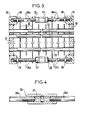
- FIG. 3 thus shows a modular tubular bundle according to the invention. It comprises two tubular plates 20 and 21, a set of tubes 22 and a set of support spacer plates 23. Each tubular plate is surrounded by a reinforcing frame: 24 for the tubular plate 20 and 25 for the tubular plate 21. These frames reinforcements are welded to their respective tube plate. Finally, a series of tie rods 26 connect the two plates and allow, by means of an adjustment of their length, shown in enlarged view in FIG. 4, to adjust the spacing of the plates exactly. The tie rods are spaced approximately 500 mm apart. At least some of the support spacer plates 23 are connected to the tie rods 26 to aeeroitre the rigidity of the assembly.
- the adjustment system comprises a sleeve 27 having a bore passing right through it and tapped on one side with a pitch to the right and on the other with a pitch to the left.
- the tie rods 26 are in two parts 26a and 26b screwing into the sleeve.
- the frames 24 and 25 and the tie rods 26 and the support spacer plates 23 provide the assembly with excellent rigidity.
- the module is symmetrical, the tubular plates having the same dimension on the right and on the left.
- FIG. 5 shows the way in which a module, such as that shown in FIG. 3, is assembled with three other identical modules, the whole being mounted in a condenser jacket.
- the condenser comprises an outer casing 29 partially shown.
- a flange 30 is welded to the casing so as to allow all of the four assembled modules to be fixed in the casing.
- This figure 5 represents only a small part but the whole is symmetrical, the assembly being identical on the right and on the left as well as above and below.
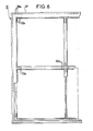
- the modules are assembled together by means of a flange 31 bearing on the four frames 25 of the four modules that we want to assemble.
- FIG. 6 shows the geometry of this flange 31.
- the fixing is carried out by means of studs 32 passing through holes 32a of the flange 31, and nuts 33.
- Two seals 34 and 35 are interposed around the periphery of each frame 25 of each module between the flange 31 and the respective frames 25.
- support bars 36 are interposed all along the flange in 500 mm sections between the nuts 33 and the flange 31.
- the external perimeter of the flange 31 carries an external extension 37 extending beyond the external perimeter of the complete tubular bundle assembled so as to fix the assembly against the flange 30 by means of threaded rods 38 passing through holes 38a of the flange, and nuts 39 and 40, fixing at the same time the water box 41 provided with an assembly flange 42.
- Two seals 43 and 44 are interposed between the outer edge 37 of the flange 31 and the flange 30 .
- a support frame 45 and a seal 46 are interposed between the flange 42 and the flange 31.
- FIG. 7 is an enlarged view of the surrounded part VII of FIG. 5.
- FIG 8 shows a variant of Figure 7 in which the seals 34, 35 are protected by a hydraulic barrier.
- each reinforcing frame 25 has a counterbore 47 over its entire periphery, this counterbore being connected by a channel 48 and 49 to a water inlet not shown at a pressure higher than the cooling water arriving in the box. water 41 ( Figure 5).
- the support plates 36 are then replaced by thick washers 50, individual. Seals 51 and 52 are interposed between the flange 31 and the washers 50 and between the washers 50 and the rods 32.
- the flange 31 is fixed to the frames 25 of the modules by screwing means, which constitutes a preferred embodiment.
- screwing means which constitutes a preferred embodiment.
Landscapes
- Engineering & Computer Science (AREA)
- Mechanical Engineering (AREA)
- General Engineering & Computer Science (AREA)
- Physics & Mathematics (AREA)
- Thermal Sciences (AREA)
- Details Of Heat-Exchange And Heat-Transfer (AREA)
- Heat-Exchange Devices With Radiators And Conduit Assemblies (AREA)
- Sorption Type Refrigeration Machines (AREA)
- Resistance Heating (AREA)
Applications Claiming Priority (2)
| Application Number | Priority Date | Filing Date | Title |
|---|---|---|---|
| FR8309229A FR2547035B1 (fr) | 1983-06-03 | 1983-06-03 | Faisceau tubulaire modulaire pour condenseur de vapeur |
| FR8309229 | 1983-06-03 |
Publications (2)
| Publication Number | Publication Date |
|---|---|
| EP0128452A1 true EP0128452A1 (de) | 1984-12-19 |
| EP0128452B1 EP0128452B1 (de) | 1986-12-03 |
Family
ID=9289455
Family Applications (1)
| Application Number | Title | Priority Date | Filing Date |
|---|---|---|---|
| EP84106106A Expired EP0128452B1 (de) | 1983-06-03 | 1984-05-29 | Modular-Röhrenbündel für Dampfkondensator und Dampfkondensator mit einem solchen Bündel |
Country Status (8)
| Country | Link |
|---|---|
| US (1) | US4559996A (de) |
| EP (1) | EP0128452B1 (de) |
| JP (1) | JPS6141885A (de) |
| KR (1) | KR930000654B1 (de) |
| CA (1) | CA1271377A (de) |
| DE (1) | DE3461562D1 (de) |
| ES (1) | ES8503121A1 (de) |
| FR (1) | FR2547035B1 (de) |
Cited By (3)
| Publication number | Priority date | Publication date | Assignee | Title |
|---|---|---|---|---|
| WO2001031277A1 (en) * | 1999-10-26 | 2001-05-03 | Tetra Laval Holdings & Finance Sa | An arrangement in a tube heat exchanger |
| EP1126227A1 (de) * | 2000-02-09 | 2001-08-22 | ALSTOM POWER (Schweiz) AG | Dampfkondensator |
| FR3044395A1 (fr) * | 2015-11-27 | 2017-06-02 | Eiffage Construction Metallique | Echangeur de chaleur a plaque tubulaire renforcee |
Families Citing this family (9)
| Publication number | Priority date | Publication date | Assignee | Title |
|---|---|---|---|---|
| US4708197A (en) * | 1985-11-01 | 1987-11-24 | Robbins R Ralph | Air to air heat exchanger |
| US4962810A (en) * | 1989-09-18 | 1990-10-16 | Rockwell International Corporation | Heat exchanger |
| EP1769740A1 (de) | 2005-10-03 | 2007-04-04 | Unomedical Limited | Biomedizinische Elektrode, ein Gel zur Verwendung mit einer biomedizinischen Elektrode und ein Verfahren zur Herstellung der biomedizinischen Elektrode |
| US8534346B1 (en) | 2006-11-16 | 2013-09-17 | Climatecraft Technologies, Inc. | Flexible heat exchanger |
| US20110024082A1 (en) * | 2009-05-09 | 2011-02-03 | Tranter, Inc. | Heat exchanger with accessible core |
| US20100314083A1 (en) * | 2009-06-12 | 2010-12-16 | George Williams | Condenser Shell and Tube Bundle Support Plate Construction |
| JP5546853B2 (ja) * | 2009-12-25 | 2014-07-09 | 株式会社東芝 | 復水器および復水器の組み立て方法 |
| JP6291886B2 (ja) * | 2014-02-12 | 2018-03-14 | 新日鐵住金株式会社 | 伝熱管の交換方法 |
| US12235052B1 (en) * | 2021-09-26 | 2025-02-25 | Leon Sanders | Heat exchanger bolt assembly |
Citations (5)
| Publication number | Priority date | Publication date | Assignee | Title |
|---|---|---|---|---|
| FR420242A (fr) * | 1909-11-17 | 1911-01-25 | Pauline Tholer | Condenseur de vapeur |
| US2237903A (en) * | 1940-01-25 | 1941-04-08 | Robert W Drake | Open type condenser |
| US2401889A (en) * | 1942-09-18 | 1946-06-11 | Rca Corp | Secret telephony |
| FR1211918A (fr) * | 1957-12-23 | 1960-03-18 | Foster Wheeler Ltd | échangeurs de chaleur perfectionnés |
| FR2126323A1 (de) * | 1971-02-23 | 1972-10-06 | Sanne Et Wendel As |
Family Cites Families (16)
| Publication number | Priority date | Publication date | Assignee | Title |
|---|---|---|---|---|
| US704454A (en) * | 1900-06-18 | 1902-07-08 | Henry A Ferguson | Feed-water heater and condenser. |
| US1842945A (en) * | 1930-12-04 | 1932-01-26 | Griscom Russell Co | Heat exchanger |
| US1918608A (en) * | 1931-03-04 | 1933-07-18 | Alco Products Inc | Apparatus for condensing hydrocarbons |
| US2059967A (en) * | 1933-08-05 | 1936-11-03 | Charles H Leach | Heat exchange apparatus |
| US2036957A (en) * | 1936-02-19 | 1936-04-07 | Griscom Russell Co | Heat exchanger |
| US2181486A (en) * | 1938-03-19 | 1939-11-28 | Andale Co | Heat exchange equipment |
| GB674652A (en) * | 1950-01-26 | 1952-06-25 | Howard Iron Works Inc | Improvements in tube bundle assembly for heat exchangers |
| US2552416A (en) * | 1945-09-26 | 1951-05-08 | American Locomotive Co | Heat exchanger |
| US2595822A (en) * | 1949-10-25 | 1952-05-06 | Young Radiator Co | Spring seal for tube and shell heat exchangers |
| US3231015A (en) * | 1963-05-01 | 1966-01-25 | Babcock & Wilcox Co | Graphite-plate heat exchange apparatus |
| US3332477A (en) * | 1965-01-05 | 1967-07-25 | Richmond Engineering Company I | Water heating apparatus |
| US3861460A (en) * | 1973-05-23 | 1975-01-21 | Laval Turbine | Condenser construction |
| US3986549A (en) * | 1975-07-14 | 1976-10-19 | Modine Manufacturing Company | Heat exchanger |
| US4253516A (en) * | 1978-06-22 | 1981-03-03 | Westinghouse Electric Corp. | Modular heat exchanger |
| US4202407A (en) * | 1978-07-24 | 1980-05-13 | Didier Engineering Gmbh | Apparatus for cooling gases from coke plants |
| JPS5664285A (en) * | 1979-10-31 | 1981-06-01 | Toshiba Corp | Condensor |
-
1983
- 1983-06-03 FR FR8309229A patent/FR2547035B1/fr not_active Expired
-
1984
- 1984-05-29 EP EP84106106A patent/EP0128452B1/de not_active Expired
- 1984-05-29 DE DE8484106106T patent/DE3461562D1/de not_active Expired
- 1984-05-30 US US06/615,188 patent/US4559996A/en not_active Expired - Lifetime
- 1984-06-01 CA CA000455675A patent/CA1271377A/fr not_active Expired - Lifetime
- 1984-06-01 KR KR1019840003050A patent/KR930000654B1/ko not_active Expired - Fee Related
- 1984-06-01 ES ES533065A patent/ES8503121A1/es not_active Expired
- 1984-06-01 JP JP11289984A patent/JPS6141885A/ja active Granted
Patent Citations (5)
| Publication number | Priority date | Publication date | Assignee | Title |
|---|---|---|---|---|
| FR420242A (fr) * | 1909-11-17 | 1911-01-25 | Pauline Tholer | Condenseur de vapeur |
| US2237903A (en) * | 1940-01-25 | 1941-04-08 | Robert W Drake | Open type condenser |
| US2401889A (en) * | 1942-09-18 | 1946-06-11 | Rca Corp | Secret telephony |
| FR1211918A (fr) * | 1957-12-23 | 1960-03-18 | Foster Wheeler Ltd | échangeurs de chaleur perfectionnés |
| FR2126323A1 (de) * | 1971-02-23 | 1972-10-06 | Sanne Et Wendel As |
Cited By (5)
| Publication number | Priority date | Publication date | Assignee | Title |
|---|---|---|---|---|
| WO2001031277A1 (en) * | 1999-10-26 | 2001-05-03 | Tetra Laval Holdings & Finance Sa | An arrangement in a tube heat exchanger |
| US8196644B1 (en) | 1999-10-26 | 2012-06-12 | Tetra Laval Holdings & Finance Sa | Arrangement in a tube heat exchanger |
| EP1126227A1 (de) * | 2000-02-09 | 2001-08-22 | ALSTOM POWER (Schweiz) AG | Dampfkondensator |
| US6360543B2 (en) | 2000-02-09 | 2002-03-26 | Alstom (Schweiz) Ag | Steam condenser |
| FR3044395A1 (fr) * | 2015-11-27 | 2017-06-02 | Eiffage Construction Metallique | Echangeur de chaleur a plaque tubulaire renforcee |
Also Published As
| Publication number | Publication date |
|---|---|
| KR930000654B1 (ko) | 1993-01-29 |
| EP0128452B1 (de) | 1986-12-03 |
| FR2547035A1 (fr) | 1984-12-07 |
| ES533065A0 (es) | 1985-02-01 |
| US4559996A (en) | 1985-12-24 |
| KR850000655A (ko) | 1985-02-28 |
| FR2547035B1 (fr) | 1987-06-26 |
| JPS6141885A (ja) | 1986-02-28 |
| JPH0228791B2 (de) | 1990-06-26 |
| DE3461562D1 (en) | 1987-01-15 |
| CA1271377A (fr) | 1990-07-10 |
| ES8503121A1 (es) | 1985-02-01 |
Similar Documents
| Publication | Publication Date | Title |
|---|---|---|
| EP0128452B1 (de) | Modular-Röhrenbündel für Dampfkondensator und Dampfkondensator mit einem solchen Bündel | |
| EP0173027B1 (de) | Abgedichtete Verbindung zwischen einem Rohr, einem Rohrknie und einem metallischen Flansch für eine thermoelektrische Anlage | |
| EP0501855A1 (de) | Rohrschlangenwärmetauscher | |
| EP0376839A1 (de) | Ausdehnungsvorrichtung zum Anbringen zwischen zwei Rohren | |
| FR2545594A1 (fr) | Echangeur de chaleur | |
| EP0544579B1 (de) | Wärmetauscher mit U-Rohren und Anti-Auftriebshalterung | |
| EP0382108A1 (de) | Laser mit Halterungsvorrichtung des aktiven Materials und Halterungsvorrichtung für den Laseraufbau | |
| US7724453B2 (en) | Vacuum cell for optical components | |
| EP0010499A1 (de) | Verbesserungen an Wärmetauschern | |
| FR2568363A1 (fr) | Echangeur de chaleur de secours pour le refroidissement du fluide primaire d'un reacteur nucleaire et procede de montage de cet echangeur de chaleur | |
| FR2642578A1 (fr) | Ligne blindee | |
| EP0095717A1 (de) | Heiztunnel | |
| FR2732081A1 (fr) | Verin support de structures lourdes et fragiles, tel un miroir de telescope | |
| EP0379115B1 (de) | Überhitzerrohrbündel für einen horizontalen Dampfabscheider-Zwischenüberhitzer | |
| CA1305430C (fr) | Module pour elements cylindriques rigides a membrane de separation, de filtration ou de transformation catalytique | |
| EP3771799B1 (de) | Rahmen im kostengünstigen set für festen, drehbaren oder schiebe-öffnungsflügel eines tors | |
| FR2554208A1 (fr) | Panneau d'obturation provisoire d'un passage a l'interieur d'une enceinte accessible seulement par un orifice de plus petites dimensions | |
| FR2473609A1 (fr) | Chassis vitre en deux parties assemblees pour portes et fenetres | |
| EP4235011B1 (de) | Behälter mit einem ausrüstungsträger, der an verschiedene einrichtungen angeschlossen sind, und verfahren zur herstellung des besagten behälters | |
| EP0601253B1 (de) | Heizkessel aus Gusseisen | |
| FR2692495A3 (fr) | Module filtrant. | |
| EP0127554A1 (de) | Bauteile für räumliche Tragkonstruktionen | |
| FR2658583A1 (fr) | Dispositif de raccordement et d'etancheite pour deux tuyaux montes bout a bout. | |
| CH679514A5 (en) | Assembly method for sealing metallic ducts - connecting duct edges have double folds which locate inside sliding square channel, with seal provided between abutting edges | |
| EP4224085A1 (de) | Schalung für eine luftbehandlungsanlage |
Legal Events
| Date | Code | Title | Description |
|---|---|---|---|
| PUAI | Public reference made under article 153(3) epc to a published international application that has entered the european phase |
Free format text: ORIGINAL CODE: 0009012 |
|
| AK | Designated contracting states |
Designated state(s): BE CH DE FR GB IT LI NL SE |
|
| 17P | Request for examination filed |
Effective date: 19850611 |
|
| GRAA | (expected) grant |
Free format text: ORIGINAL CODE: 0009210 |
|
| AK | Designated contracting states |
Kind code of ref document: B1 Designated state(s): BE CH DE FR GB IT LI NL SE |
|
| REF | Corresponds to: |
Ref document number: 3461562 Country of ref document: DE Date of ref document: 19870115 |
|
| ITF | It: translation for a ep patent filed | ||
| PLBE | No opposition filed within time limit |
Free format text: ORIGINAL CODE: 0009261 |
|
| STAA | Information on the status of an ep patent application or granted ep patent |
Free format text: STATUS: NO OPPOSITION FILED WITHIN TIME LIMIT |
|
| 26N | No opposition filed | ||
| ITTA | It: last paid annual fee | ||
| EAL | Se: european patent in force in sweden |
Ref document number: 84106106.2 |
|
| REG | Reference to a national code |
Ref country code: GB Ref legal event code: IF02 |
|
| PGFP | Annual fee paid to national office [announced via postgrant information from national office to epo] |
Ref country code: CH Payment date: 20020416 Year of fee payment: 19 |
|
| PGFP | Annual fee paid to national office [announced via postgrant information from national office to epo] |
Ref country code: NL Payment date: 20020430 Year of fee payment: 19 |
|
| PGFP | Annual fee paid to national office [announced via postgrant information from national office to epo] |
Ref country code: SE Payment date: 20020502 Year of fee payment: 19 Ref country code: GB Payment date: 20020502 Year of fee payment: 19 |
|
| PGFP | Annual fee paid to national office [announced via postgrant information from national office to epo] |
Ref country code: DE Payment date: 20020511 Year of fee payment: 19 |
|
| PGFP | Annual fee paid to national office [announced via postgrant information from national office to epo] |
Ref country code: FR Payment date: 20020513 Year of fee payment: 19 |
|
| PGFP | Annual fee paid to national office [announced via postgrant information from national office to epo] |
Ref country code: BE Payment date: 20020527 Year of fee payment: 19 |
|
| PG25 | Lapsed in a contracting state [announced via postgrant information from national office to epo] |
Ref country code: GB Free format text: LAPSE BECAUSE OF NON-PAYMENT OF DUE FEES Effective date: 20030529 |
|
| PG25 | Lapsed in a contracting state [announced via postgrant information from national office to epo] |
Ref country code: SE Free format text: LAPSE BECAUSE OF NON-PAYMENT OF DUE FEES Effective date: 20030530 |
|
| PG25 | Lapsed in a contracting state [announced via postgrant information from national office to epo] |
Ref country code: LI Free format text: LAPSE BECAUSE OF NON-PAYMENT OF DUE FEES Effective date: 20030531 Ref country code: CH Free format text: LAPSE BECAUSE OF NON-PAYMENT OF DUE FEES Effective date: 20030531 Ref country code: BE Free format text: LAPSE BECAUSE OF NON-PAYMENT OF DUE FEES Effective date: 20030531 |
|
| BERE | Be: lapsed |
Owner name: *DELAS-WEIR Effective date: 20030531 |
|
| PG25 | Lapsed in a contracting state [announced via postgrant information from national office to epo] |
Ref country code: NL Free format text: LAPSE BECAUSE OF NON-PAYMENT OF DUE FEES Effective date: 20031201 |
|
| PG25 | Lapsed in a contracting state [announced via postgrant information from national office to epo] |
Ref country code: DE Free format text: LAPSE BECAUSE OF NON-PAYMENT OF DUE FEES Effective date: 20031202 |
|
| EUG | Se: european patent has lapsed | ||
| REG | Reference to a national code |
Ref country code: CH Ref legal event code: PL |
|
| GBPC | Gb: european patent ceased through non-payment of renewal fee |
Effective date: 20030529 |
|
| PG25 | Lapsed in a contracting state [announced via postgrant information from national office to epo] |
Ref country code: FR Free format text: LAPSE BECAUSE OF NON-PAYMENT OF DUE FEES Effective date: 20040130 |
|
| NLV4 | Nl: lapsed or anulled due to non-payment of the annual fee |
Effective date: 20031201 |
|
| REG | Reference to a national code |
Ref country code: FR Ref legal event code: ST |