EP0128657B1 - Vorrichtung zum automatischen Montieren oder Demontieren einer mit einer Welle versehenen hohlen Kassettenrolle - Google Patents
Vorrichtung zum automatischen Montieren oder Demontieren einer mit einer Welle versehenen hohlen Kassettenrolle Download PDFInfo
- Publication number
- EP0128657B1 EP0128657B1 EP19840303011 EP84303011A EP0128657B1 EP 0128657 B1 EP0128657 B1 EP 0128657B1 EP 19840303011 EP19840303011 EP 19840303011 EP 84303011 A EP84303011 A EP 84303011A EP 0128657 B1 EP0128657 B1 EP 0128657B1
- Authority
- EP
- European Patent Office
- Prior art keywords
- roller
- spindles
- caps
- compressed air
- air cylinder
- Prior art date
- Legal status (The legal status is an assumption and is not a legal conclusion. Google has not performed a legal analysis and makes no representation as to the accuracy of the status listed.)
- Expired
Links
- 238000012545 processing Methods 0.000 claims description 30
- 239000007788 liquid Substances 0.000 claims description 9
- 238000007789 sealing Methods 0.000 description 8
- 230000008878 coupling Effects 0.000 description 6
- 238000010168 coupling process Methods 0.000 description 6
- 238000005859 coupling reaction Methods 0.000 description 6
- 238000007747 plating Methods 0.000 description 4
- 238000011282 treatment Methods 0.000 description 3
- 239000004020 conductor Substances 0.000 description 2
- 230000000694 effects Effects 0.000 description 2
- 238000000034 method Methods 0.000 description 2
- 239000012811 non-conductive material Substances 0.000 description 2
- 238000002203 pretreatment Methods 0.000 description 2
- 230000005540 biological transmission Effects 0.000 description 1
- 238000009713 electroplating Methods 0.000 description 1
- 238000003754 machining Methods 0.000 description 1
- 239000000463 material Substances 0.000 description 1
- 238000012986 modification Methods 0.000 description 1
- 230000004048 modification Effects 0.000 description 1
- 238000012856 packing Methods 0.000 description 1
- 230000002093 peripheral effect Effects 0.000 description 1
- 239000004033 plastic Substances 0.000 description 1
- 229920003023 plastic Polymers 0.000 description 1
Images


Classifications
-
- C—CHEMISTRY; METALLURGY
- C25—ELECTROLYTIC OR ELECTROPHORETIC PROCESSES; APPARATUS THEREFOR
- C25D—PROCESSES FOR THE ELECTROLYTIC OR ELECTROPHORETIC PRODUCTION OF COATINGS; ELECTROFORMING; APPARATUS THEREFOR
- C25D7/00—Electroplating characterised by the article coated
- C25D7/04—Tubes; Rings; Hollow bodies
Definitions
- the present invention relates to an apparatus for automatically mounting and demounting cassette-type rollers, having a shaft that can be adapted to a facility for processing the outer surfaces of rollers, to plate outer surfaces of rollers, to effect pre-treatment or after-treatment for plating, or to effect buffing. More specifically, the present invention relates to an improved apparatus for automatically mounting and demounting cassette-type rollers, having a shaft which is separate from a line facility having a plurality of required processing devices or from conveyor means suspended from the ceiling of the line, but which is suspended from the conveyer means, and which is conveyed to required processing devices in the line facility, such that the roller with both ends being chucked can be subjected to the required processings in the processing devices.
- Such apparatus forms the subject of our European Published Application No. 0032954A.
- Fig. 1 is a sectional view of the above-mentioned apparatus for automatically mounting and demounting cassette-type hollow rollers.
- the apparatus X for automatically mounting and demounting cassette-type hollow rollers comprises a lifting frame 1, a pair of rotary spindles 2, 3, facing each other at both ends of the lifting frame 1, a pair of electrically conductive support members 4, 5 which are provided on free ends of said pair of spindles 2, 3, which support the hollow roller R between the spindles, and which permit flow of electric current, a pair of leak-proof caps 6, 7 which are annularly formed on the outer sides of the electrically conductive support members 4, 5, and which come into contact with the end surfaces of the hollow roller to prevent a processing liquid from infiltrating into the interior of the hollow roller, an air cylinder device 8 which is mounted on the lifting frame to move the spindles 2, 3 at least in the axial direction, air cylinder chambers 9, 10 which are formed between the spindles and the leak-proof caps, and which drive the leak-proof caps 6, 7 toward the end surface of the roller being powered by the compressed air, and a compressed air supply means 11 which has a compressed air tank 11a and which supplies compressed air to the air
- the lifting frame 1 is formed of a pair of vertical frames 1a, 1a which are provided at both ends of the frame and face each other, and which are placed on processing devices of the line facility, and a coupling frame 1b for coupling the pair of vertical frames.
- the coupling frame is formed of a cylindrical member and has a compressed air supply port to also serve as the compressed air tank 11a.
- the spindle 3 on the right side of Fig. 1 is equipped with a sprocket 14.
- the apparatus X for automatically mounting and demounting cassette-type hollow rollers is placed on a roller R that is to be treated and that is placed on a roller mounting/demounting plate, not shown.
- the roller is moved to the right so that a tapered hole at the right end of the roller is fitted over the electrically conductive support member 5 located on the right.
- the lever of a switching valve 12 is moved from position (b) to position (a), to supply compressed air in the compressed air tank 11a into a cylinder chamber in the bottom of the air cylinder device 8, whereby a piston 8a is pushed out, and the electrically conductive support member 4 at the end of the left spindle-2 is fitted to a tapered hole formed in the left end of the roller R.
- roller R is chucked.
- the roller in the form of a cassette is then placed on the right and left frames 41, 40 of a predetermined processing device Y in the line facility as shown in Fig. 2.
- leak-prevention plates 42a, 42b, 42c, 42d each being split in two toward the right and left, operate to close the leak-proof caps 6, 7 to prevent the leakage of liquid.
- the sprocket 14 engages with a chain of a chain transmission device or with a gear of a gear device, which is not shown, so that the right spindle 3 is driven by a motor 43.
- the roller R supported by the right and left spindles 3, 2, spins and is immersed in the processing liquid in a processing vessel S, so that a predetermined processing is effected (plating, pre-treatment or after-treatment).
- a predetermined processing is effected (plating, pre-treatment or after-treatment).
- an electric current is supplied to the roller R via the right and left spindles and the electrically conductive support members 4, 5.
- the roller R is then conveyed to another processing device in the line facility and is subjected to a predetermined processing.
- the apparatus for automatically mounting and demounting cassette-type hollow rollers is conveyed to the mounting/demounting plate by a conveyer, not shown, but which is suspended from the ceiling of the line.
- the switching valve 13 is then returned to initial position (d) to release the compressed air in the air cylinder chambers 9, 10 into the atmosphere, whereby the leakproof caps 6, 7 are separated from the end surfaces of the roller.
- the switching valve 12 is then returned to initial position (b), the compressed air in the compressed air tank 11a is supplied into the cylinder chamber on the head side of the air cylinder device 8, to retract the piston 8a.
- the left electrically conductive support member 4 is then separated away from the roller R.
- roller R If pushed leftwards by hand in Fig. 2, the roller R can be taken out.
- the above-mentioned apparatus for automatically mounting and demounting cassette-type rollers can only be used with hollow rollers. Therefore, modification of the apparatus is required so that it can also be used with rollers having a shaft.
- the present invention was devised in view of the above-mentioned respects, and provides an apparatus for automatically mounting and demounting cassette-type rollers, having a shaft in which the electrically conductive support members are replaceable, depending upon the types of the rollers to be processed, the leak-proof caps are made up of movable caps which slide on the outer side of the spindles and replaceable exchange caps which are fitted to the outer periphery of shafts of the roller, and which are pressed onto the movable caps to press the end surfaces of the roller, wherein the electrically conductive support members and the exchange caps are suitably selected so as to be adapted to the roller having a shaft of any size, length or shape.
- the present invention provides an apparatus for automatically mounting and demounting cassette-type rollers, having a shaft, comprising:
- the lifting frame may be formed of a pair of vertical side frames that are provided at both ends facing each other and that are placed on a line facility, and a coupling frame which also serves as a compressed air tank for the compressed air supply means, and which couples said pair of vertical side frames as a unitary structure.
- Two compressed air tanks may be provided, one for the air cylinder device and the other for the air cylinder chambers.
- the electrically conductive support members are selected depending upon the type of roller to be treated and are fitted to the shaft portion of the roller.
- the electrically conductive support members have spindle-engaging portions that will engage with the spindles, viz: the spindle-engaging portions are secured to the spindles by bolts, or are screwed into the spindles, or are coupled with the spindles through a spline, or are simply fitted to the spindles.
- the electrically conductive support members further have shaft-engaging portions that engage with the shaft portion of the roller.
- the shaft-engaging portions are engaged with the shaft portion of the roller and are then engaged with the spindles.
- the shaft-engaging portions engage with the shaft portion of the roller after the spindle-engaging portions have engaged with the spindles.
- the electrically conductive support members should be mounted so as to be engaged with further support members which are provided at the ends of the spindles.
- the leak-proof caps comprise movable caps and replaceable exchange caps.
- the outer surfaces of the caps should be made of electrically nonconductive material. Further, the caps should be made of a heat-resistant plastics material and be of a cylindrical shape, and should have a sealing member at the ends adjacent the end surface of the roller.
- the replaceable exchange caps should have shaft-engaging portions so that they are supported in a stable manner by the shaft portion of the roller to be treated, or should have additional engaging portions so as to be supported by the movable caps.
- replaceable exchange caps having additional engaging portions are so mounted as to be added to the movable caps.
- the replaceable exchange caps are engaged with the shaft portion of the roller when they have shaft-engaging portions.
- the end surfaces of the movable caps and the replaceable exchange caps are brought into contact with each other so as to maintain the interior thereof in an air-tight manner.
- the interior is maintained in an air-tight manner by the tapered fitting, or by using a seal packing. No limitation, however, is imposed on the method of maintaining the caps air-tight.
- a single replaceable exchange cap will suffice.
- a single replaceable exchange cap may not be sufficient so as to be mounted in a stable manner on the periphery of the shaft.
- two or more replaceable exchange caps may be provided.
- each cap should be butted in series in the axial direction to maintain the interior air-tight.
- the replaceable exchange cap should have a cylindrical shape which can be mounted in a stable manner on the outer periphery of the roller to be treated, and should be butted to the movable cap to accomplish sealing.
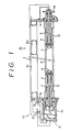
- the apparatus for automatically mounting and demounting cassette-type rollers having a shaft comprises a pair of spindles 2, 3 facing each other and provided at each end of a gate-shaped lifting frame 1, electrically conductive support members 4, 5 which are selectively replaceable, located at the ends of the spindles 2, 3 depending upon the type of roller, leak-proof caps 6, 7 located around the outer periphery of the spindles and electrically conductive support members, the leak-proof caps 6, 7 being composed of movable caps 6a, 7a and replaceable exchange caps 6b, 7b, and compressed air supply means 11 with a compressed air tank 11a.
- the compressed air is supplied to the air cylinder device 8 and to the air cylinder chambers 9, 10 to drive the spindle 2 in the axial direction.
- the movable caps 6a, 7a are moved towards the direction of the end surface of the roller to press the exchange caps 6b, 7b which are fitted to the shaft portion of the roller R that is to be treated.
- the interior of the caps is maintained air-tight, and the roller is chucked at both ends.
- the lifting frame 1 comprises a pair of vertical side frames 1a, 1a that face each other at each end and that are placed on a required processing device in the line facility, and a coupling frame 1b which couples the pair of side frames together.
- the coupling frame 1b comprises a cylindrical member and has a compressed air supply port, not shown, to also work as a compressed air tank 11a.
- the pairs of spindles 2, 3 are made of an electrically conductive material, provided on the pair of side frames 1a, 1a, facing each other in a horizontal line, and slide relative to power-feed brushes which are provided on the side of the line facility to be served with electric power.
- the spindle 2 on the left side in the drawing is rotatably supported by the cylindrical piston 8a made of an electrically nonconductive material in the air cylinder device 8 which is secured at the lower end of the side frame 1a of the lifting frame 1 on the left side in the drawing. Therefore, the spindle 2 is allowed to spin and to move in the axial direction.
- the spindle 3 on the right side of the drawing is supported by a cylindrical bearing box 15 which is provided at the lower end of the side frame 1a on the right side.
- the air cylinder chamber 9. is formed between a stepped portion of the spindle 2 and a stepped portion in the inner surface of the leak-proof cap 6. Further, the air cylinder chamber 10 is formed between a stepped portion of the spindle 3 and a stepped portion in the inner surface of the leak- proof cap 7.
- the leak-proof caps 6, 7 are brought into contact with the end surfaces of the roller by compressed air which is supplied into the air cylinder chambers 9, 10. The pressure in the compressed air tank 11a is detected by a pressure gauge, not shown. Springs 16, 17 are fitted between the leak-proof caps 6, 7 and the corresponding small-diameter portions of the spindles 2, 3 to return the leak-proof caps 6, 7.
- the pair of electrically conductive support members 4, 5 are made of an electrically conductive material, and are fitted to the support members provided at the ends of the spindles 2, 3 in the axial direction, and work to support the roller therebetween and to enable electric current to flow. According to this embodiment, the electrically conductive support members 4, 5 are selected and replaceable depending upon the size of the shaft portion of the roller R. The support members 4, 5 are engaged with the spindles 2, 3 when the roller is to be chucked, and are fitted to the shaft portion of the roller R prior to chucking the roller.
- Support members 18, 19 are attached to the ends of the spindles 2, 3 to support the electrically conductive support members 4, 5.
- the pair of leak-proof caps 6, 7 consist of movable caps 6a, 7a and replaceable exchange caps 6b, 7b.
- the movable caps 6a, 7a are slidably fitted to the outer periphery of the spindles 2, 3 so as to be driven by compressed air which is supplied into the air cylinder chambers 9, 10, and have a ring-like sealing member 20 made of rubber at the ends close to the roller to produce sealing function.
- the replaceable exchange caps 6b, 7b are annular parts which are separate from the movable caps 6a, 7a, and are selectively replaced depending upon the type of roller R that is to be treated.
- the replaceable exchange caps 6b, 7b further assume a cylindrical shape and are stably fitted to the shaft portion of the roller R that is to be treated.
- the replaceable exchange caps 6b, 7b have a ring-like sealing member 21 made of rubber at the ends close to the roller to produce sealing function.
- Bellows cylinders 22, 23 are provided between the leak-proof caps 6, 7 and the side frames 1a, 1a to cover the spindles 2, 3.
- the compressed air supply means 11 works to supply compressed air stored in the compressed air tank 11a to the air cylinder device 8 and to the air cylinder chambers 9, 10.
- the air cylinder device 8 By manipulating the switching valve 12, the air cylinder device 8 can be driven to extend or retract the piston 8a. By manipulating the switching valve 13, furthermore, the leak-proof caps 6, 7 can be actuated.
- Flange-like drain boards 35, 36 are provided at positions corresponding to an over-flow vessel of the line facility on the outer side of the leak-proof caps 6, 7.
- the apparatus X for automatically mounting and demounting cassette-type rollers having a shaft is placed on the roller R that is to be treated and that is placed on the roller mounting/demounting plate, not shown.
- the roller is then moved to the right in the drawing.
- the electrically conductive support members 4, 5 fitted to the shaft portion at the right end of the roller are then fitted to support members at the ends of the spindles 2, 3. Thus, one end of the roller is engaged.
- the lever of switching valve 12 is then shifted from position (b) to position (a) to introduce compressed air in the compressed air tank 11a into the cylinder chamber in the bottom of the air cylinder device 8 via pipe 24, switching valve 12 and pipe 25, to push out the piston 8a.
- the support member 18 at the end of the spindle 2 then engages with the support member 4 fitted to the end of the shaft portion on the left of the roller. Thus, both ends of the roller are chucked.
- the roller R to be treated is sandwiched in the axial direction by the support members 4, 5. Therefore, a heavy current is allowed to flow into the roller.
- the cassette is conveyed by a conveyer means, not shown, suspended from the ceiling of the line to a processing device in the line facility to perform a required processing.
- the apparatus X for automatically mounting and demounting cassette-type rollers having a shaft is placed on the mounting/demounting plate, and the lever of switching valve 13 is returned to position (d). Compressed air in the air cylinder chambers 9, 10 then escapes into the open air through the switching valve 13, and the movable caps 6a, 7a separate away from the replaceable exchange caps 6b, 7b and return to the initial positions being urged by the springs 16, 17.
- the spindle 3 separates away from the support member 5, whereby the roller is freed.
- the apparatus X for automatically mounting and demounting cassette-type rollers having a shaft is then suspended, and the electrically conductive support members 4, 5 and replaceable exchange caps 6b, 7b are removed from the shaft portions of the roller R.
- the support members 4, 5 and replaceable exchange caps 6b, 7b are selected to suit the roller.
- the support members 4, 5 may not be fitted to shaft portions at both ends of the roller, but may be fitted to the support members provided at the ends of the spindles 2, 3.
- the apparatus for automatically mounting and demounting cassette-type rollers having a shaft of the present invention as explained in the foregoing, at least one of the pair of spindles facing each other and provided at both ends of the lifting frame is moved in the axial direction by the air cylinder device which is driven by the compressed air supply means which has a compressed air tank.
- the electrically conductive support members, provided at the ends of the spindles can be selected and replaced depending upon the type of roller.
- the leak-proof caps fitted to the circumference of the spindles and the electrically conductive support members to maintain the interior thereof air-tight, are made up of movable caps and replaceable exchange caps.
- the movable caps form air cylinder chambers relative to the spindles and, hence, move toward the end surfaces of the roller when compressed air is introduced into the air cylinder chambers from the compressed air tank. Further, the replaceable exchange caps can be selected and replaced depending upon the type of roller.
- the apparatus described for use with hollow rollers can be improved so as to be adapted to rollers, having a shaft in addition to the rollers of the sleeve type. Further, the improvement does not restrict the apparatus to be adapted to rollers of one type only, but permits the apparatus to be adapted to rollers of any type having shafts of different sizes and lengths.
- the electrically conductive support members and replaceable exchange caps are prepared to suit for rollers of all types, they can be replaced depending upon the type of roller, i.e., the apparatus can be adapted to rollers, having any lengths or having shafts of any shapes. Further, electrically conductive support members and replaceable exchange caps can be easily replaced.
Landscapes
- Chemical & Material Sciences (AREA)
- Engineering & Computer Science (AREA)
- Chemical Kinetics & Catalysis (AREA)
- Electrochemistry (AREA)
- Materials Engineering (AREA)
- Metallurgy (AREA)
- Organic Chemistry (AREA)
- Electroplating Methods And Accessories (AREA)
- Finish Polishing, Edge Sharpening, And Grinding By Specific Grinding Devices (AREA)
- Cleaning And De-Greasing Of Metallic Materials By Chemical Methods (AREA)
Claims (1)
- Ein Gerät zum automatischen Montieren und Demontieren von Kassetten-Walzen, mit einer Welle, enthaltend:ein Hubrahmen,ein Paar gegenüberliegender, drehbar im Hubrahmen gelagerter Spindeln,ein Paar elektrisch leitender Stützorgane an den freien Enden des Paares von Spindeln, um eine-zu behandelnde Walze zwischen den Spindein zu stützen,ein Paar von ringförmigen, dichtenden Hülsen an den Aussenseiten der elektrisch leitenden Stützorgane, welche sich gegen die Stirnflächen der Walze anlegen, um eine Behandlungsflüssigkeit am Eindringen in die Seite der elektrisch leitenen Stützorgane, zu hindern,eine Luftzylindervorrichtung, welche auf dem Hubrahmen montiert ist und mindestens eine der Spindeln in axialer Richtung antreibt,Luftzylinderkammern, welche zwischen den Spindeln und den dichtenden Hülsen gebildet sind welche die dichtenden Hülsen mittels Druckluft gegen die Stirnflächen der Walze Druckluft anlegen, undDruckluftspeisemittel mit einem Druckluftbehälter um Druckluft an die Luftzylindervorrichtung und an die Luftzylinderkammern zu liefern,dadurch gekennzeichnet, dass die elektrisch leitenden Stützorgane (4, 5) ersetzbar und in Abhängigkeit der Art der Walze (R) gewählt sind, und dass sie wellenangreifenden Teile aufweisen, die mit der Welle der Walze angreifen und diese stützen, und spindelangreifenden Teile, die mit den Spindeln (2, 3) im eingriff stehen und diese stützen, wobeidie dichtenden Hülsen abnehmbare Hülsen (6a, 7a) aufweisen, die an die Aussenseiten der Spindeln (2, 3) angebracht sind und durch Druckluft, welche an den Luftzylinderkammern (9, 10) geliefert ist, angetrieben werden, und ersetzbare Hülsen (6b, 7b), die in Abhängigkeit der Art der Walze gewählt sind und welche Luftundurchlässigkeit am Umfang der Spindeln zwischen den abnehmbaren Hülsen (6a, 7a) und die Stirnflächen der Walze (R) aufrechtrerhalten, wenn die Walze montiert werden muss.
Applications Claiming Priority (2)
| Application Number | Priority Date | Filing Date | Title |
|---|---|---|---|
| JP80981/83 | 1983-05-11 | ||
| JP8098183A JPS59208099A (ja) | 1983-05-11 | 1983-05-11 | カセツト型ロ−ル自動脱着装置 |
Publications (2)
| Publication Number | Publication Date |
|---|---|
| EP0128657A1 EP0128657A1 (de) | 1984-12-19 |
| EP0128657B1 true EP0128657B1 (de) | 1987-02-11 |
Family
ID=13733676
Family Applications (1)
| Application Number | Title | Priority Date | Filing Date |
|---|---|---|---|
| EP19840303011 Expired EP0128657B1 (de) | 1983-05-11 | 1984-05-04 | Vorrichtung zum automatischen Montieren oder Demontieren einer mit einer Welle versehenen hohlen Kassettenrolle |
Country Status (3)
| Country | Link |
|---|---|
| EP (1) | EP0128657B1 (de) |
| JP (1) | JPS59208099A (de) |
| DE (1) | DE3462374D1 (de) |
Families Citing this family (2)
| Publication number | Priority date | Publication date | Assignee | Title |
|---|---|---|---|---|
| WO1996001336A1 (de) * | 1994-07-01 | 1996-01-18 | Ecograph Ag | Stromzuführungs- und antriebs-adapter für druckzylinder |
| CH694861A5 (de) * | 2000-05-04 | 2005-08-15 | Ecograph Ag | Vorrichtung zum Einspannen von Druckzylindern und Drehen derselben in Galvanik-Anlagen. |
Family Cites Families (5)
| Publication number | Priority date | Publication date | Assignee | Title |
|---|---|---|---|---|
| US3462357A (en) * | 1967-03-13 | 1969-08-19 | Pamarco Inc | Plating fixture |
| US3616447A (en) * | 1969-01-21 | 1971-10-26 | Eastman Kodak Co | Apparatus for suspending a body in a corrosive solution |
| US3664944A (en) * | 1969-10-29 | 1972-05-23 | Udylite Corp | Electroplating apparatus |
| US4340450A (en) * | 1980-07-09 | 1982-07-20 | Shinku Laboratory Co., Ltd. | Method for plating rollers and apparatus for mounting rollers utilized in the method |
| US4317706A (en) * | 1980-07-09 | 1982-03-02 | Shinku Laboratory Co., Ltd. | Apparatus for plating a printing roller |
-
1983
- 1983-05-11 JP JP8098183A patent/JPS59208099A/ja active Pending
-
1984
- 1984-05-04 DE DE8484303011T patent/DE3462374D1/de not_active Expired
- 1984-05-04 EP EP19840303011 patent/EP0128657B1/de not_active Expired
Also Published As
| Publication number | Publication date |
|---|---|
| JPS59208099A (ja) | 1984-11-26 |
| EP0128657A1 (de) | 1984-12-19 |
| DE3462374D1 (en) | 1987-03-19 |
Similar Documents
| Publication | Publication Date | Title |
|---|---|---|
| KR100234539B1 (ko) | 반도체장치 제조용 식각 장치 | |
| CN115896906B (zh) | 一种水平式自动上片机 | |
| EP0032954B1 (de) | Eine automatisch arbeitende Einspann- und Ausspannvorrichtung vom Kassetten-Typ für Hohlwalzen | |
| US4519887A (en) | Apparatus for automatically attaching and detaching cassette-type rolls | |
| EP0128657B1 (de) | Vorrichtung zum automatischen Montieren oder Demontieren einer mit einer Welle versehenen hohlen Kassettenrolle | |
| CN109482384B (zh) | 轴或汽车发动机喷油管的自动喷涂装置 | |
| US4340450A (en) | Method for plating rollers and apparatus for mounting rollers utilized in the method | |
| CN109482385B (zh) | 轴或汽车发动机喷油管的自动喷涂方法 | |
| KR890000595B1 (ko) | 고속유성 선회식 배럴가공법 및 가공기 | |
| CN116475773B (zh) | 一种液压衬套自动化组装生产线 | |
| CN112354943A (zh) | 酒盖清洗装置及其方法 | |
| CN212705382U (zh) | 一种球阀的手柄用装配设备 | |
| JPH0573540B2 (de) | ||
| JP3267835B2 (ja) | 表面処理方法及びその装置 | |
| KR102048881B1 (ko) | 엔코더를 통해 샤프트에 형성된 스케일을 판독하여 위치를 검출하는 웨이퍼 이송장치 | |
| US4317706A (en) | Apparatus for plating a printing roller | |
| JP3946490B2 (ja) | 放電加工機及びその操作方法 | |
| CN220277769U (zh) | 一种新型真空等离子的表面处理机 | |
| KR20000012946U (ko) | 쵸크의 베어링 교체 및 세척장치 | |
| JP3276240B2 (ja) | ピストンマスクの自動装着装置および自動離脱装置 | |
| CN216298520U (zh) | 一种支重轮整体装配工装 | |
| CN223509129U (zh) | 电池外壳翻转输送装置 | |
| CN115463880B (zh) | 轴承内外圈的清洗转台及设备 | |
| CN213592203U (zh) | 一种新型自动锁螺丝机 | |
| JPS5810475B2 (ja) | カセツト形中空ロ−ル脱着装置 |
Legal Events
| Date | Code | Title | Description |
|---|---|---|---|
| PUAI | Public reference made under article 153(3) epc to a published international application that has entered the european phase |
Free format text: ORIGINAL CODE: 0009012 |
|
| AK | Designated contracting states |
Designated state(s): CH DE FR GB IT LI |
|
| 17P | Request for examination filed |
Effective date: 19850531 |
|
| 17Q | First examination report despatched |
Effective date: 19860123 |
|
| GRAA | (expected) grant |
Free format text: ORIGINAL CODE: 0009210 |
|
| ITF | It: translation for a ep patent filed | ||
| AK | Designated contracting states |
Kind code of ref document: B1 Designated state(s): CH DE FR GB IT LI |
|
| REF | Corresponds to: |
Ref document number: 3462374 Country of ref document: DE Date of ref document: 19870319 |
|
| ET | Fr: translation filed | ||
| PLBE | No opposition filed within time limit |
Free format text: ORIGINAL CODE: 0009261 |
|
| STAA | Information on the status of an ep patent application or granted ep patent |
Free format text: STATUS: NO OPPOSITION FILED WITHIN TIME LIMIT |
|
| 26N | No opposition filed | ||
| ITTA | It: last paid annual fee | ||
| REG | Reference to a national code |
Ref country code: GB Ref legal event code: IF02 |
|
| PGFP | Annual fee paid to national office [announced via postgrant information from national office to epo] |
Ref country code: GB Payment date: 20020514 Year of fee payment: 19 |
|
| PGFP | Annual fee paid to national office [announced via postgrant information from national office to epo] |
Ref country code: FR Payment date: 20020527 Year of fee payment: 19 |
|
| PGFP | Annual fee paid to national office [announced via postgrant information from national office to epo] |
Ref country code: CH Payment date: 20020529 Year of fee payment: 19 |
|
| PGFP | Annual fee paid to national office [announced via postgrant information from national office to epo] |
Ref country code: DE Payment date: 20020711 Year of fee payment: 19 |
|
| PG25 | Lapsed in a contracting state [announced via postgrant information from national office to epo] |
Ref country code: GB Free format text: LAPSE BECAUSE OF NON-PAYMENT OF DUE FEES Effective date: 20030504 |
|
| PG25 | Lapsed in a contracting state [announced via postgrant information from national office to epo] |
Ref country code: LI Free format text: LAPSE BECAUSE OF NON-PAYMENT OF DUE FEES Effective date: 20030531 Ref country code: CH Free format text: LAPSE BECAUSE OF NON-PAYMENT OF DUE FEES Effective date: 20030531 |
|
| PG25 | Lapsed in a contracting state [announced via postgrant information from national office to epo] |
Ref country code: DE Free format text: LAPSE BECAUSE OF NON-PAYMENT OF DUE FEES Effective date: 20031202 |
|
| GBPC | Gb: european patent ceased through non-payment of renewal fee |
Effective date: 20030504 |
|
| REG | Reference to a national code |
Ref country code: CH Ref legal event code: PL |
|
| PG25 | Lapsed in a contracting state [announced via postgrant information from national office to epo] |
Ref country code: FR Free format text: LAPSE BECAUSE OF NON-PAYMENT OF DUE FEES Effective date: 20040130 |
|
| REG | Reference to a national code |
Ref country code: FR Ref legal event code: ST |