EP0128710A2 - Procédé et dispositif pour charger un moule - Google Patents
Procédé et dispositif pour charger un moule Download PDFInfo
- Publication number
- EP0128710A2 EP0128710A2 EP84303687A EP84303687A EP0128710A2 EP 0128710 A2 EP0128710 A2 EP 0128710A2 EP 84303687 A EP84303687 A EP 84303687A EP 84303687 A EP84303687 A EP 84303687A EP 0128710 A2 EP0128710 A2 EP 0128710A2
- Authority
- EP
- European Patent Office
- Prior art keywords
- mold
- powder
- charge
- box
- charge box
- Prior art date
- Legal status (The legal status is an assumption and is not a legal conclusion. Google has not performed a legal analysis and makes no representation as to the accuracy of the status listed.)
- Granted
Links
Images



Classifications
-
- B—PERFORMING OPERATIONS; TRANSPORTING
- B29—WORKING OF PLASTICS; WORKING OF SUBSTANCES IN A PLASTIC STATE IN GENERAL
- B29C—SHAPING OR JOINING OF PLASTICS; SHAPING OF MATERIAL IN A PLASTIC STATE, NOT OTHERWISE PROVIDED FOR; AFTER-TREATMENT OF THE SHAPED PRODUCTS, e.g. REPAIRING
- B29C41/00—Shaping by coating a mould, core or other substrate, i.e. by depositing material and stripping-off the shaped article; Apparatus therefor
- B29C41/34—Component parts, details or accessories; Auxiliary operations
- B29C41/36—Feeding the material on to the mould, core or other substrate
-
- B—PERFORMING OPERATIONS; TRANSPORTING
- B29—WORKING OF PLASTICS; WORKING OF SUBSTANCES IN A PLASTIC STATE IN GENERAL
- B29C—SHAPING OR JOINING OF PLASTICS; SHAPING OF MATERIAL IN A PLASTIC STATE, NOT OTHERWISE PROVIDED FOR; AFTER-TREATMENT OF THE SHAPED PRODUCTS, e.g. REPAIRING
- B29C41/00—Shaping by coating a mould, core or other substrate, i.e. by depositing material and stripping-off the shaped article; Apparatus therefor
- B29C41/02—Shaping by coating a mould, core or other substrate, i.e. by depositing material and stripping-off the shaped article; Apparatus therefor for making articles of definite length, i.e. discrete articles
- B29C41/18—Slush casting, i.e. pouring moulding material into a hollow mould with excess material being poured off
-
- B—PERFORMING OPERATIONS; TRANSPORTING
- B29—WORKING OF PLASTICS; WORKING OF SUBSTANCES IN A PLASTIC STATE IN GENERAL
- B29L—INDEXING SCHEME ASSOCIATED WITH SUBCLASS B29C, RELATING TO PARTICULAR ARTICLES
- B29L2031/00—Other particular articles
- B29L2031/30—Vehicles, e.g. ships or aircraft, or body parts thereof
Definitions
- This invention relates to a process and apparatus for the manufacture of thin-walled articles from a powdered thermoplastic and more particularly to the manufacture of such articles by use of a re-claiming and make-up powder supply and associated method and means for uniform distribution of thermoplastic powder against a heated mold surface which causes the powder to become fused.
- An object of the present invention is to provide an improved process and apparatus for loading an open-ended heated mold with powder plastisol material by the process of releasing a pre-charge of thermoplastic powder through the major axis of a charge box for gravity flow into the mold and by the provision of means to produce such release during a pre-selected mold machine operation.
- Another object of the present invention is to provide an improved process for formation of hollow parts from thermoplastic powder material including the steps of loading an open-ended charge box with a predetermined quantity of powder; clamping the loaded open-ended charge box to an open-ended mold to form a closed system; sealing the mold from the powder content in the charge box while concurrently rotating the closed system so that the charge box is located vertically above the mold and thereafter releasing the powder from the charge box to flow evenly across the open end of the mold by gravity so as to produce a uniform thin coat build-up across heated surfaces of the mold.
- Another object of the present invention is to provide a plastics molding apparatus having a gravity fill system for flow of powder material into a heated mold to form a thin walled hollow plastic part and for return of excess powder material from the mold including a charge box having a plurality of louvers extending across an open end of the powder box, the open end having a planar extent at least equal to the planar extent of the end of an associated mold; means for coupling the powder box to the mold to define a rotatable closed system and means for operating the louvers to close communication between the powder box interior and mold interior during a pre-fill phase wherein the closed system is rotated to dispose the charge box above the mold for gravity flow of powder into the mold and said means being operable to open the louvers to produce even gravity flow of powder across the open end of the mold so as to uniformly coat heated surfaces of the material with plastic.
- a further object of the present invention is to provide a plastics molding apparatus as set forth in the preceding object wherein means are provided to invert the closed system and air blast excess unfused plastic material from the mold to gravity dump it into the powder box for use in a subsequent mold cycle.
- the mold is pivotally supported on a frame and the charge box is selectively moved beneath the mold and coupled to the mold for concurrent rotation therewith on the frame.
- the charge box has a plurality of louvers at an open end thereof selectively opened and closed to control flow of powder from the mold during rotation of the box to a vertically upper position for an even gravity flow distribution of a powder charge from the box into the mold so as to produce a uniform thin build-up of plastic particles on heated surfaces of the mold.
- the charge box further includes a longitudinal bar type air jet system operable when the charge box is in a receiver position for gravity flow return of excess powder from the mold to the charge box for use in a subsequent mold fill cycle.
- the process and apparatus of the present invention will be with reference to the production of plastic thin-walled hollow parts for a typical automotive part such as a skin for an instrument panel crash pad having a length of about 60 inches, a surface of approximately 17 square feet and a volume of about 6900 cubic inches.
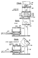
- a start and pre-heat step is shown in an automated powder molding process line which is schematically shown as including a powder charge box 20 mounted on a wheeled cart 22 driven by a hydraulic drive cylinder 24 .to the start-pre-heat step position in the process sequence.
- box 20 includes a bottom 26 supported on an elevator platform 28 supported for vertical reciprocation on guide columns 30 fixed at each corner of the cart 22.
- the platform 28 is driven between raised and lowered positions by a pneumatic bellows-type piston 32 selectively pressurized and deflated by diagramatically illustrated air supply system 34.
- the piston 32 In the start pre-heat position of Figure 1 the piston 32 is deflated and the platform 28 is in a retracted position on the cart 22 whereby the box 20 is free to move beneath a selectively heated mold 36 of the type set forth in USPN 4,217,325 August 12, 1980 issued to D. Colby. While this patent shows a slush mold system for plastisol, its mold and heating and cooling cycles are representative of those for pre-heating the mold 36 in the process sequence set forth in the start-preheat step of Figure 1.
- the box 20 further includes an upper open end 38 which is configured to cover the planar extent of a charge opening 39 to mold 36.
- the open end 38 is opened and closed by a charge control valve 40 for evenly distributing powder from box into the mold 36 during a fill or mold loading step in which mold 36 and box are disposed as shown in Figure 3.
- Valve 40 more particularly, includes a plurality of louvers 42, shown in Figure 9, each carried by a rotatable shaft 44.
- Each louver 42 extends across the length of box 20 and is of a width sufficient to overlap an adjacent louver 42 when the valve 40 is closed.
- Each louver 42 includes an edge seal 46 which engages the underside of an adjacent louver when closed.
- the outer louvers 42 have a pair of such seals to seal against the box as well as an adjacent louver 42.
- Each shaft 44 extends through opposite end walls 48, 50 of the box 20 to rotatably support the louvers 42 on the box 20.
- One end of each shaft as viewed in Figure 11 is connected tc a sprocket 52.
- a drive chain loop 54 across the sprockets 52 is operated by a suitable drive cylinder 56 connected to loop 54 by link 58.
- Cylinder 56 is operated by known controls to open and close the louvers.
- the box 20 further includes a clamp assembly 60 including spaced clamp plates 62 movably reciprocated on bo y 20 by a drive cylinder 64. Each plate has a tapered slot 6E that selectively captures or releases a pair of spaced pins 68 on mold 36.
- the clamp assembly 60 is closed when the powder charge box 20 is elevated by piston 32 as shown in Figures 2 and 7. At this step of the process the cylinder 64 is pressurized to move plates 62 into a lock position shown in Figure 7.
- the interior 70 of box 20 and the interior 72 of mold 36 form a closed system 74 having a powder charg ⁇ only in interior 70 at start and preheat.
- the next process step includes concurrent rotation of the closed system 74 about trunnions 76 on machine frame 78
- the closed louvers 42 withhold introduction of the powder until the most favorable orientation of box 20 and mold 36.
- the valve assembly 40 remains closed as shown in Figure 9 and the valve assembly 40 only opens once the charge box 20 is located vertically above the mold.
- a Fill step of the process takes place.
- the drive cylinder 56 is conditioned to rotate the drive chain loop 54 to cause each louver 42 to assume the dotted line position shown in Figure 9.
- a plurality of closely spaced powder feed passages 80 are defined end-to-end and side-to-side of mold charge opening 39 through which thermoplastic powder is distributed evenly throughout the charge opening 39.
- a resultant even build-up of melted plastic occurs on the heated walls of the mold.
- the louvers contribute to a fluidizing effect when they are opened and the powder starts to pour through the openings. While this is happening, the air in the mold must find its way through the powder to replace the void in the box which improves fluidization and eliminates air traps which otherwise occur in nearly 50% of the moldings if the louvers are left open during rotation to fill, and decrease to 0% when louvers are opened after the box has reached the upper position.
- An air-jet system 82 is then actuated to dislodge excess powder from the walls of the mold.
- Valve 40 is opened so that the dislodged material will flow by gravity return to the interior 70 of the box through its open end for collection and reuse in the system.
- a fuse cycle is then carried out in accordance with known practice for example as set forth in USPN 3,492,307 wherein the molded powder is completely fused into the desired thin walled hollow part.
- the charge box is unclamped from the inverted mold and the bellows-type piston returns box 20 to the retracted carriage position for return to a make-up position to one side of the mold.
- the mold is cooled and rotated into a strip position shown in Figure 6.
- Make-up powder is fed through suitable supply means shown as a chute 84 and the valve 40 which is disposed in its open position.
- the air jet system 82 is in the form of an oscillating air sweep tube 88. As shown in Figure 11 tube 88 is driven by right angle bevel gears 90, 92 connected to one end of tube 88 and a vertical drive shaft 94. The drive components are covered by box 96 and tube 98 to prevent wear.
- a hydraulic motor 100 drives a chain loop 102 across sprockets 104, 106 to oscillate the tube 88 so that an air jet covers all surfaces of the mold including ledges, undercuts and other detail shapes found on complex shapes such as automobile crash pads.
- louver system includes a separate louver rack 110 having side inserts 112 (one shown in Figure 14) to narrow the flow opening 114 through which powder flows from a charge box 116 into a mold (now shown).
- the rack 110 is connected by a series of spaced clamps 118 to the box 116.
- Each louver 120 has a shaft 122 pivotally supported by side walls of the rack 110. They are driven by a drive system (not shown) of the type described in the louver drive system shown in Figures 8 and 9.
- an air jet system 124 is located closely adjacent the opening 114 so as to be directly in line with the peripheral region of a mold connected to the box.
- the air jet system 124 includes an elongated tube 126 which extends across the width of opening 114.
- Tube 126 has a journal 128 on one end and an air supply inlet fitting 130 on its opposite end as shown in Figure 16.
- Individual jets 132 are spaced on the tube 126 along its length to remove excess powder from the mold.
- Oscillation of tube 126 is produced by a drive motor 134 having its shaft coupled by a link 136 to a drive chain loop 138 that extends across a drive sprocket 140 connected to the outboard end 142 of tube 126 and an idler sprocket 144.
- thermoplastic powders are plasticized polyvinyl chlorides and related vinyl resins in dry powder form for ease of gravity flow passage through valve passages 80 during both fill and return steps.
- Typical examples of parts, plastic materials and mold processes include the following:
- volume of each mold was approximately four cubic feet.
- PVC resin, plasticizer, stabilizer, release agents and color pigments are combined in a high intensity mixer to produce a dry, flowable powder.
- the process is known in the industry as dry-blending.
- the various compound components may be selected as to type and ratio to provide the properties required both for the finished product and for ease of processing. Physical properties will not be too dissimilar from those obtained with liquid plastisol which is also used to manufacture similar products but has an inherent weakness for forming objectionable drips and runs when made in complex shapes.
- Processing properties are such that when melting of the plastic powder occurs, densification results in exact reproduction of minute detail such as grain marks and stitches engraved in the mold surface.
- Mold preheating temperature may range from 320°F to 390°F. Since the thickness of the finished product is also governed by the time the powder contacts the mold, it should be understood that simultaneous charging of the powder to the mold can be of definite advantage. Also, if certain areas of the mold can be made to have a lower pre-heated temperature than others, it will permit molding a thinner shell in those areas, since both temperature and mold-filled time determine the final thickness of the shell. Therefore, a very flexible range, for mold-filled time, of one second to ten seconds or more has been established.
- the powder must contact all areas of the mold that constitute part of the desired finished product. However, since the box can be contoured to match almost any given shape or mold periphery, then additional savings can be gained by reducing the surface area of the mold below that which would be required for liquid plastisol casting.
- the air sweep can operate effectively in the range of 40 to 90 psi and at least one oscillation in each direction should be made by the air jet assembly for best results.
- Each oscillation should not take more than two seconds to complete the full arc of movement and initiation of the air sweep should commence within five seconds after dumping the powder out of the mold. Any delay will cause the excess powder to melt and prevent its being blown free.
- the mold After fusion, the mold is cooled to a temperature which will facilitate removal of the shell without damage.
- a typical molding cycle is as follows:
- thermoplastic powder material onto mold surfaces to form large, long, thin-walled hollow parts such as automobile crash pads formed during short cycle mold cycles in limited plant floor space.
Landscapes
- Engineering & Computer Science (AREA)
- Mechanical Engineering (AREA)
- Moulding By Coating Moulds (AREA)
Applications Claiming Priority (2)
| Application Number | Priority Date | Filing Date | Title |
|---|---|---|---|
| US50076083A | 1983-06-03 | 1983-06-03 | |
| US500760 | 1983-06-03 |
Publications (3)
| Publication Number | Publication Date |
|---|---|
| EP0128710A2 true EP0128710A2 (fr) | 1984-12-19 |
| EP0128710A3 EP0128710A3 (en) | 1986-11-05 |
| EP0128710B1 EP0128710B1 (fr) | 1989-03-29 |
Family
ID=23990811
Family Applications (1)
| Application Number | Title | Priority Date | Filing Date |
|---|---|---|---|
| EP19840303687 Expired EP0128710B1 (fr) | 1983-06-03 | 1984-06-01 | Procédé et dispositif pour charger un moule |
Country Status (6)
| Country | Link |
|---|---|
| EP (1) | EP0128710B1 (fr) |
| JP (1) | JPS6052319A (fr) |
| AU (1) | AU575053B2 (fr) |
| CA (1) | CA1237564A (fr) |
| DE (1) | DE3477479D1 (fr) |
| MX (1) | MX158975A (fr) |
Cited By (4)
| Publication number | Priority date | Publication date | Assignee | Title |
|---|---|---|---|---|
| EP0208432A3 (en) * | 1985-07-01 | 1988-06-08 | Ex-Cell-O Corporation | Mould method and apparatus for plastic shells |
| FR2787379A1 (fr) * | 1998-12-21 | 2000-06-23 | S M C A | Installation de moulage de matieres plastiques par embouage |
| FR2873054A1 (fr) * | 2004-07-15 | 2006-01-20 | Faurecia Interieur Ind Snc | Procede pour realiser par rotomoulage une peau presentant une zone affaiblie |
| NL2004198C2 (nl) * | 2010-02-05 | 2011-08-08 | Kersten Kunststofcoating B V | Werkwijze en inrichting voor het bekleden van een object met een kunststof bekledingsmateriaal. |
Families Citing this family (1)
| Publication number | Priority date | Publication date | Assignee | Title |
|---|---|---|---|---|
| JPS6390089U (fr) * | 1986-12-01 | 1988-06-11 |
Family Cites Families (7)
| Publication number | Priority date | Publication date | Assignee | Title |
|---|---|---|---|---|
| FR1131153A (fr) * | 1954-05-10 | 1957-02-18 | Nat Res Dev | Machine à mouler des enveloppes de moulage |
| US3492307A (en) * | 1967-02-27 | 1970-01-27 | Goodyear Tire & Rubber | Method for molding thermoplastic material |
| US3565986A (en) * | 1967-04-03 | 1971-02-23 | Goodyear Tire & Rubber | Method of heating electroform molds |
| US3506755A (en) * | 1967-06-12 | 1970-04-14 | Goodyear Tire & Rubber | Molding apparatus and methods |
| BE759576A (fr) * | 1969-11-28 | 1971-04-30 | Aquitaine Total Organico | Procede de fabrication de corps creux ouverts ou fermes constitues de deux couches de matieres thermoplastiques et corps creux realises par ledit procede |
| US4217325A (en) * | 1977-04-21 | 1980-08-12 | Mccord Corporation | Method using modular slush molding machine |
| US4664864A (en) * | 1983-06-03 | 1987-05-12 | Ex-Cell-O Corporation | Mold loading method and apparatus |
-
1984
- 1984-05-17 AU AU28340/84A patent/AU575053B2/en not_active Ceased
- 1984-05-30 JP JP11065084A patent/JPS6052319A/ja active Granted
- 1984-06-01 MX MX20152784A patent/MX158975A/es unknown
- 1984-06-01 CA CA000455732A patent/CA1237564A/fr not_active Expired
- 1984-06-01 EP EP19840303687 patent/EP0128710B1/fr not_active Expired
- 1984-06-01 DE DE8484303687T patent/DE3477479D1/de not_active Expired
Cited By (5)
| Publication number | Priority date | Publication date | Assignee | Title |
|---|---|---|---|---|
| EP0208432A3 (en) * | 1985-07-01 | 1988-06-08 | Ex-Cell-O Corporation | Mould method and apparatus for plastic shells |
| FR2787379A1 (fr) * | 1998-12-21 | 2000-06-23 | S M C A | Installation de moulage de matieres plastiques par embouage |
| EP1013388A1 (fr) * | 1998-12-21 | 2000-06-28 | S.M.C.A., Sarl | Installation de moulage de poudres |
| FR2873054A1 (fr) * | 2004-07-15 | 2006-01-20 | Faurecia Interieur Ind Snc | Procede pour realiser par rotomoulage une peau presentant une zone affaiblie |
| NL2004198C2 (nl) * | 2010-02-05 | 2011-08-08 | Kersten Kunststofcoating B V | Werkwijze en inrichting voor het bekleden van een object met een kunststof bekledingsmateriaal. |
Also Published As
| Publication number | Publication date |
|---|---|
| EP0128710B1 (fr) | 1989-03-29 |
| CA1237564A (fr) | 1988-06-07 |
| JPH044924B2 (fr) | 1992-01-29 |
| EP0128710A3 (en) | 1986-11-05 |
| JPS6052319A (ja) | 1985-03-25 |
| MX158975A (es) | 1989-04-04 |
| AU2834084A (en) | 1984-12-06 |
| AU575053B2 (en) | 1988-07-21 |
| DE3477479D1 (en) | 1989-05-03 |
Similar Documents
| Publication | Publication Date | Title |
|---|---|---|
| US4664864A (en) | Mold loading method and apparatus | |
| US4722678A (en) | Rotational mold with valved charge box | |
| US4562025A (en) | Mold method and apparatus for multi-color plastic shells | |
| US4610620A (en) | Apparatus for molding plural colored plastic hollow shells | |
| US3217078A (en) | Process for molding hollow articles from thermoplastic materials | |
| US4780345A (en) | Mold method and apparatus for multi-color plastic shells | |
| US4634360A (en) | Rotational mold for making multi-color plastic shells | |
| US4552715A (en) | Process for producing a molded skin product | |
| US4692293A (en) | Mold method for multi-color plastic shells | |
| EP0128710B1 (fr) | Procédé et dispositif pour charger un moule | |
| JPS6250106A (ja) | プラスチツクシエルの為の成型方法及び装置 | |
| JPS609715A (ja) | 合成樹脂薄壁物体を製造する方法および装置 | |
| US3897527A (en) | Method of manufacturing articles from hot solid filler material coated with thermoplastic material | |
| US4947923A (en) | Method and apparatus for evaporative pattern casting | |
| US5062470A (en) | Method and apparatus for treating gaseous material from evaporative pattern casting | |
| US4969971A (en) | Apparatus for producing fibre-reinforced thermoplastic material for the production mouldings | |
| JPS62282629A (ja) | 連続式流動層造粒装置 | |
| GB2046152A (en) | A Molding Machine | |
| EP0307005A2 (fr) | Coquilles multi-colorées en matière plastique | |
| JPH02238912A (ja) | 中空部を有する成形品の成形方法 | |
| JPS62253417A (ja) | 表皮材のスラツシユ成形法およびその成形装置 | |
| JPH02310015A (ja) | 二層表皮合成樹脂製品の製造方法 | |
| JPH0233507B2 (ja) | Goseijushihyohitainoseizoho | |
| CA1271611A (fr) | Coques plastiques polychromes | |
| GB2103141A (en) | Recycling waste plastics material |
Legal Events
| Date | Code | Title | Description |
|---|---|---|---|
| PUAI | Public reference made under article 153(3) epc to a published international application that has entered the european phase |
Free format text: ORIGINAL CODE: 0009012 |
|
| AK | Designated contracting states |
Designated state(s): DE FR GB IT SE |
|
| PUAL | Search report despatched |
Free format text: ORIGINAL CODE: 0009013 |
|
| AK | Designated contracting states |
Kind code of ref document: A3 Designated state(s): DE FR GB IT SE |
|
| 17P | Request for examination filed |
Effective date: 19870224 |
|
| 17Q | First examination report despatched |
Effective date: 19870717 |
|
| GRAA | (expected) grant |
Free format text: ORIGINAL CODE: 0009210 |
|
| RAP1 | Party data changed (applicant data changed or rights of an application transferred) |
Owner name: DAVIDSON TEXTRON INC |
|
| AK | Designated contracting states |
Kind code of ref document: B1 Designated state(s): DE FR GB IT SE |
|
| REF | Corresponds to: |
Ref document number: 3477479 Country of ref document: DE Date of ref document: 19890503 |
|
| ITF | It: translation for a ep patent filed | ||
| ET | Fr: translation filed | ||
| PLBE | No opposition filed within time limit |
Free format text: ORIGINAL CODE: 0009261 |
|
| STAA | Information on the status of an ep patent application or granted ep patent |
Free format text: STATUS: NO OPPOSITION FILED WITHIN TIME LIMIT |
|
| 26N | No opposition filed | ||
| PGFP | Annual fee paid to national office [announced via postgrant information from national office to epo] |
Ref country code: SE Payment date: 19910527 Year of fee payment: 8 |
|
| PGFP | Annual fee paid to national office [announced via postgrant information from national office to epo] |
Ref country code: FR Payment date: 19920515 Year of fee payment: 9 Ref country code: DE Payment date: 19920515 Year of fee payment: 9 |
|
| PGFP | Annual fee paid to national office [announced via postgrant information from national office to epo] |
Ref country code: GB Payment date: 19920529 Year of fee payment: 9 |
|
| PG25 | Lapsed in a contracting state [announced via postgrant information from national office to epo] |
Ref country code: SE Effective date: 19920602 |
|
| PG25 | Lapsed in a contracting state [announced via postgrant information from national office to epo] |
Ref country code: GB Effective date: 19930601 |
|
| GBPC | Gb: european patent ceased through non-payment of renewal fee |
Effective date: 19930601 |
|
| PG25 | Lapsed in a contracting state [announced via postgrant information from national office to epo] |
Ref country code: FR Effective date: 19940228 |
|
| PG25 | Lapsed in a contracting state [announced via postgrant information from national office to epo] |
Ref country code: DE Effective date: 19940301 |
|
| REG | Reference to a national code |
Ref country code: FR Ref legal event code: ST |
|
| EUG | Se: european patent has lapsed |
Ref document number: 84303687.2 Effective date: 19930109 |