EP0129052A1 - Procédé de fabrication des aimants permanents cylindriques - Google Patents
Procédé de fabrication des aimants permanents cylindriques Download PDFInfo
- Publication number
- EP0129052A1 EP0129052A1 EP84105452A EP84105452A EP0129052A1 EP 0129052 A1 EP0129052 A1 EP 0129052A1 EP 84105452 A EP84105452 A EP 84105452A EP 84105452 A EP84105452 A EP 84105452A EP 0129052 A1 EP0129052 A1 EP 0129052A1
- Authority
- EP
- European Patent Office
- Prior art keywords
- magnetic
- compact
- anisotropy
- compacting
- permanent magnet
- Prior art date
- Legal status (The legal status is an assumption and is not a legal conclusion. Google has not performed a legal analysis and makes no representation as to the accuracy of the status listed.)
- Granted
Links
- 238000000034 method Methods 0.000 title claims abstract description 24
- 230000005291 magnetic effect Effects 0.000 claims abstract description 104
- 239000000843 powder Substances 0.000 claims abstract description 34
- 230000005294 ferromagnetic effect Effects 0.000 claims abstract description 24
- 229910052751 metal Inorganic materials 0.000 claims abstract description 19
- 239000002184 metal Substances 0.000 claims abstract description 19
- 230000005405 multipole Effects 0.000 claims abstract description 17
- 230000002093 peripheral effect Effects 0.000 claims abstract description 16
- 238000010304 firing Methods 0.000 claims abstract description 5
- 125000006850 spacer group Chemical group 0.000 claims description 16
- 239000000696 magnetic material Substances 0.000 claims description 8
- 230000002441 reversible effect Effects 0.000 claims description 2
- 230000006835 compression Effects 0.000 claims 1
- 238000007906 compression Methods 0.000 claims 1
- 230000035699 permeability Effects 0.000 claims 1
- 230000004907 flux Effects 0.000 description 33
- 238000004519 manufacturing process Methods 0.000 description 6
- 238000010276 construction Methods 0.000 description 5
- 230000003247 decreasing effect Effects 0.000 description 5
- 229910000859 α-Fe Inorganic materials 0.000 description 5
- 238000012360 testing method Methods 0.000 description 4
- 238000011160 research Methods 0.000 description 3
- 229910045601 alloy Inorganic materials 0.000 description 2
- 239000000956 alloy Substances 0.000 description 2
- 239000003990 capacitor Substances 0.000 description 2
- 238000009826 distribution Methods 0.000 description 2
- 230000005415 magnetization Effects 0.000 description 2
- 239000000463 material Substances 0.000 description 2
- 230000004048 modification Effects 0.000 description 2
- 238000012986 modification Methods 0.000 description 2
- 238000005096 rolling process Methods 0.000 description 2
- VRDIULHPQTYCLN-UHFFFAOYSA-N Prothionamide Chemical compound CCCC1=CC(C(N)=S)=CC=N1 VRDIULHPQTYCLN-UHFFFAOYSA-N 0.000 description 1
- 239000011230 binding agent Substances 0.000 description 1
- 230000015572 biosynthetic process Effects 0.000 description 1
- CJZGTCYPCWQAJB-UHFFFAOYSA-L calcium stearate Chemical compound [Ca+2].CCCCCCCCCCCCCCCCCC([O-])=O.CCCCCCCCCCCCCCCCCC([O-])=O CJZGTCYPCWQAJB-UHFFFAOYSA-L 0.000 description 1
- 235000013539 calcium stearate Nutrition 0.000 description 1
- 239000008116 calcium stearate Substances 0.000 description 1
- 239000003795 chemical substances by application Substances 0.000 description 1
- 239000002131 composite material Substances 0.000 description 1
- 239000003822 epoxy resin Substances 0.000 description 1
- 230000001747 exhibiting effect Effects 0.000 description 1
- 238000002474 experimental method Methods 0.000 description 1
- 239000000945 filler Substances 0.000 description 1
- 230000001771 impaired effect Effects 0.000 description 1
- 238000005470 impregnation Methods 0.000 description 1
- 230000001788 irregular Effects 0.000 description 1
- 239000006247 magnetic powder Substances 0.000 description 1
- 229910001172 neodymium magnet Inorganic materials 0.000 description 1
- 239000002245 particle Substances 0.000 description 1
- 229920000647 polyepoxide Polymers 0.000 description 1
- 230000008569 process Effects 0.000 description 1
- 229910052761 rare earth metal Inorganic materials 0.000 description 1
- 150000002910 rare earth metals Chemical class 0.000 description 1
- 230000009467 reduction Effects 0.000 description 1
- 239000012779 reinforcing material Substances 0.000 description 1
- 238000005245 sintering Methods 0.000 description 1
- 230000001131 transforming effect Effects 0.000 description 1
- 238000004804 winding Methods 0.000 description 1
Images


Classifications
-
- C—CHEMISTRY; METALLURGY
- C08—ORGANIC MACROMOLECULAR COMPOUNDS; THEIR PREPARATION OR CHEMICAL WORKING-UP; COMPOSITIONS BASED THEREON
- C08L—COMPOSITIONS OF MACROMOLECULAR COMPOUNDS
- C08L51/00—Compositions of graft polymers in which the grafted component is obtained by reactions only involving carbon-to-carbon unsaturated bonds; Compositions of derivatives of such polymers
- C08L51/04—Compositions of graft polymers in which the grafted component is obtained by reactions only involving carbon-to-carbon unsaturated bonds; Compositions of derivatives of such polymers grafted on to rubbers
-
- H—ELECTRICITY
- H01—ELECTRIC ELEMENTS
- H01F—MAGNETS; INDUCTANCES; TRANSFORMERS; SELECTION OF MATERIALS FOR THEIR MAGNETIC PROPERTIES
- H01F41/00—Apparatus or processes specially adapted for manufacturing or assembling magnets, inductances or transformers; Apparatus or processes specially adapted for manufacturing materials characterised by their magnetic properties
- H01F41/02—Apparatus or processes specially adapted for manufacturing or assembling magnets, inductances or transformers; Apparatus or processes specially adapted for manufacturing materials characterised by their magnetic properties for manufacturing cores, coils, or magnets
- H01F41/0253—Apparatus or processes specially adapted for manufacturing or assembling magnets, inductances or transformers; Apparatus or processes specially adapted for manufacturing materials characterised by their magnetic properties for manufacturing cores, coils, or magnets for manufacturing permanent magnets
- H01F41/0273—Imparting anisotropy
- H01F41/028—Radial anisotropy
-
- B—PERFORMING OPERATIONS; TRANSPORTING
- B22—CASTING; POWDER METALLURGY
- B22F—WORKING METALLIC POWDER; MANUFACTURE OF ARTICLES FROM METALLIC POWDER; MAKING METALLIC POWDER; APPARATUS OR DEVICES SPECIALLY ADAPTED FOR METALLIC POWDER
- B22F3/00—Manufacture of workpieces or articles from metallic powder characterised by the manner of compacting or sintering; Apparatus specially adapted therefor ; Presses and furnaces
- B22F3/02—Compacting only
-
- C—CHEMISTRY; METALLURGY
- C08—ORGANIC MACROMOLECULAR COMPOUNDS; THEIR PREPARATION OR CHEMICAL WORKING-UP; COMPOSITIONS BASED THEREON
- C08F—MACROMOLECULAR COMPOUNDS OBTAINED BY REACTIONS ONLY INVOLVING CARBON-TO-CARBON UNSATURATED BONDS
- C08F279/00—Macromolecular compounds obtained by polymerising monomers on to polymers of monomers having two or more carbon-to-carbon double bonds as defined in group C08F36/00
- C08F279/02—Macromolecular compounds obtained by polymerising monomers on to polymers of monomers having two or more carbon-to-carbon double bonds as defined in group C08F36/00 on to polymers of conjugated dienes
-
- H—ELECTRICITY
- H01—ELECTRIC ELEMENTS
- H01F—MAGNETS; INDUCTANCES; TRANSFORMERS; SELECTION OF MATERIALS FOR THEIR MAGNETIC PROPERTIES
- H01F13/00—Apparatus or processes for magnetising or demagnetising
- H01F13/003—Methods and devices for magnetising permanent magnets
Definitions
- the present invention relates to a method of producing a cylindrical magnet provided with an anisotropy by compacting in a magnetic field.
- a motor for driving the magnetic disk of a computer and a motor for controlling the printer attached to the computer For such uses, a motor called "PM type of stepping motor", having a rotor constituted by a multipole cylindrical permanent magnet, is most suitably used.
- the cylindrical permanent magnet used in this motor has four or more poles, and rotors having magnetic poles greater than 8, e.g. 12, 24 or 36 poles, are becoming popular.
- isotropic ferrite magnet has been used most popularly as the cylindrical permanent magnet of the kind described.
- This magnet cannot provide satisfactory magnetic properties.
- a cylindrical permanent magnet of this type having 24 poles and being 26 mm in outside diameter, exhibits a surface magnetic flux density Bo which is as small as 900 to 950 G.
- This magnet also shows unsatisfactory magnetic properties due to the use of a binder agent for rolling and winding.
- a cylindrical permanent magnet of this type having 24 poles and being 26 mm in outside dia., shows only a small surface magnetic flux density Bo of 950 to 1050 G.
- the present invention aims as its primary object at providing a cylindrical permanent magnet having excellent magnetic properties, thereby to obviate the problems of the prior art.
- a cylindrical permanent magnet for the PM type of stepping motor As a cylindrical permanent magnet for the PM type of stepping motor, a cylindrical permanent magnet having a multipole anisotropy only in its surface is required (see Japanese Patent Application Laid-Open Publication No. 199205/82).
- a permanent magnet having surface anisotropy may be produced by compacting conducted under the influence of a magnetic field.
- the thought method cannot provide sufficiently high magnetic properties and tends to cause non-uniformity of the magnetic flux density along the length of each magnetic pole, unless a special compacting method is employed.
- fluctuation in magnetic flux density in the order of 2% or less along the length of the magnetic pole does not matter substantially and, hence, is acceptable.
- a method of producing a cylindrical permanent magnet comprising the steps of: preparing a metal mold cooperating with a lower punch in defining therein a cylindrical compacting cavity, the metal mold being provided with a magnetic field means corresponding to the magnetic poles of the magnet to be produced; charging the compacting cavity with a ferromagnetic powder having a magnetic anisotropy; energizing the magnetic field means to impart a magnetic anisotropy to the ferromagnetic powder while compacting the powder between an upper punch and the lower punch to form a compact; demagnetizing the formed compact followed by a firing; and magnetizing the fired compact in the same direction as the imparted anisotropy; characterized in that the magnetic field means produce pulse magnetic field the intensity of which is not smaller than 3.5 x 10 3 ampere-turn/m as measured at the outer peripheral surface of the compacting cavity, thereby attaining a multipole surface anisotropy on the compact.
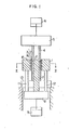
- a die 1 made of a magnetic material is fixed to the lower frame 8 through pillars 11 and_12, while a core 2 made of a non-magnetic material is connected directly to the lower frame 8 which would be driven by a lower hydraulic cylinder 9.
- An upper punch made of a non-magnetic material and supported by an upper frame 5 is disposed to project into the upper end portion of the die 1.
- a hydraulic cylinder 6 receives a piston having a rod which is connected to the upper frame 5.
- a lower punch 7 made of a non-magnetic material is fixed to a base plate 13, and would be projected partially into the lower end portion of the die 1.
- the die 1, core 2, upper punch 4 and the lower punch 7 in combination constitute a metal mold having a compacting cavity 3 defined therein.
- the compacting cavity 3 is adapted to be charged with a ferromagnetic powder 17.
- a plurality of axial slots 14 are formed in the inner peripheral surface of the die 1 defining the compacting cavity 3.
- the number of the slots 14 is equal to the number of the magnetic poles to be formed, which is usually 8 (eight) or greater.
- Each slot 14 receives wires of coils for producing magnetic fields, as will be seen from Fig. 3.
- a ring-shaped spacer 16 made of a non-magnetic material is fitted on the inner peripheral surface of the die 1.
- a cylindrical permanent magnet is produced by a method which will be explained hereinunder with specific reference to Fig. 1, using the apparatus described hereinbefore.
- the cavity 3 is charged with a ferromagnetic powder 17 such as powder of an Nd-Fe-B alloy, powder of alloy of rare earth metal and Co, Sr-ferrite powder or the like, by means of a suitable feeding device such as a vibration feeder.
- a suitable feeding device such as a vibration feeder.
- the pulse electric current is applied to the coil 15 for producing magnetic field (referred to "field coil", hereafter) to magnetically orientate the ferromagnetic powder 17.
- the upper punch 4 is driven downwardly to compact the ferromagnetic powder 17 onto a cylindrical compact, while applying pulse electric current to the field coil 15.
- the pulse electric current the direction of which is reverse to that of the electric current supplied first is then applied to the field coil 15 to demagnetize the cylindrical compact.
- the cylindrical compact is fired or sintered and is processed into desired size.
- the cylindrical compact is magnetized in the same direction as the magnetic anisotropy, so that a cylindrical permanent magnet having a multipole surface anisotropy is obtained.
- a cylindrical permanent magnet having superior magnetic properties and uniformity of magnetic flux density in axial direction (hereafter, referred to merely "linearity") can be obtained.
- a high magnetic field intensity Bg in the compacting cavity is indispensable for obtaining a large surface magnetic flux density Bo.
- the number of the magnetic poles is increased (e.g. 24 poles or more)
- the volume of each slot 14 for receiving the field coil becomes smaller, so that the number of turns of coil which can be received in each slot is naturally limited to several turns.
- the pre- send inventor has carried out various researches and found that a permanent magnet having a surface magnetic flux density Bo of 1,500 G or greater can be obtained by supplying the field coil with such pulse electric current that the magnetic field intensity becomes 3.5 x 10 ampere-turn/m or greater.
- the pulse magnetic field may be applied not only one time but also several times.
- the construction of magnetic circuit in the metal mold is important for attaining the required surface magnetic flux density Bo as mentioned above as well as the multipole surface anisotropy.
- the metal mold shown in Fig. 3 having coil-receiving slots 14 formed directly in the inner peripheral surface of the die 1 is quite effective.
- the formation of a large number of slots for multipole encounters the following problem. Namely, when a large number of axial slots are formed in the inner peripheral surface of the die 1, the cirsumferential width of each land portion la separating adjacent slots 14 becomes extremely small. Such land portions having small width may fail to withstand the large compacting pressure and may become worn down rapidly.
- the compacting pressure usually ranges between 0.5 and 1 ton/cm 2 and the lateral pressure acting on the die and the core falls within the range of 0.1 to 0.4 ton/cm 2 (Rankine coefficient assumed to b 2 0.2 to 0.4), in the case of production of ferrite type of cylindrical permanent magnet.
- the present inventor has carried out various researches and as a result found that this problem can be overcome by fitting a ring-shaped spacer 16 made of a non-magnetic material onto the inner peripheral surface of the metal mold.
- the intensity of effective magnetic flux reaching the surface of the compact is inconveniently decreased as the thickness t of the spacer is increased (in Figs. 3 and 4, the chain line represents the path of magnetic flux).
- the thickness t therefore, would be selected to meet the following condition: where, d represents the inside diameter of the spacer, while M represents the number of magnetic poles.
- Fig. 4 shows a modification of the coil-receiving slots 14.
- each slot 14 has a greater radial depth from the inner peripheral surface of the core than that in the construction shown in Fig. 3, and opens to the inside of the core 1 through a restricted opening 14a. Consequently, the land protion la between adjacent slots 14, constituting a magnetic pole, has a large circumferential width to exhibit greater mechanical strength and wear resistance.
- the thickness t of the spacer 14 should be selected to meet the above-mentioned condition also in the construction shown in Fig. 4. In the construction shown in Fig.
- the restricted opening 14a is preferably as small as possible, in order to attain higher mechanical strength and wear resistance of the land portion.
- the magnetic flux will tend to short-circuit between the adjacent land portions to undesirably decrease the intensity of magnetic flux reaching the surface of the compact. It would be possible to eliminate this problem by supplying a large pulse electric current to the field coils to magnetically saturate the short-circuitting portion.
- the slot is filled with a reinforcing material such as an epoxy resin, composite filler or the like by means of, for example, vacuum impregnation, thereby increasing the strength and the wear resistance of the metal mold.
- the application of the pulse magnetic field can be made by connecting the field coil to, for example, an instantaneous D.C. power source having a transformer/ rectifier for transforming and rectifying the commercial A.C. power into a D.C. voltage of, for example, about 700 V, the capacitors each having a capacitance of, for example, 4 x 10⁴ uF and being adapted to be charged with the D.C. voltage and a thyristor through which the capacitor make a discharge.
- an instantaneous D.C. power source having a transformer/ rectifier for transforming and rectifying the commercial A.C. power into a D.C. voltage of, for example, about 700 V
- the capacitors each having a capacitance of, for example, 4 x 10⁴ uF and being adapted to be charged with the D.C. voltage and a thyristor through which the capacitor make a discharge.
- High magnetic flux density and high uniformity or linearity of magnetic flux density along the length of the magnetic pole are the essential factors for attaining the desirable multipole surface anisotropy.
- the present inventor has found, through various experiments and study, that a high linearity of the magnetic flux density can be obtained when the compacting is conducted in a manner mentioned below.
- the cylindrical compact is formed by putting the ferromagnetic powder 17 into the compacting cavity and driving the upper punch 4 downwardly to compact the ferromagnetic powder, while applying pulse magnetic field to impart the anisotropy.
- the anisotropy is decreased in the upper portion of the compact.
- Fig. 6 shows the axial magnetic flux density distribution on each magnetic pole of a cylindrical permanent magnet which is produced by subjecting the cylindrical compact formed by the method shown in Fig. 5 to firing and magnetization. As will be seen from this Figure, the anisotropy is decreased in the portion of the magnet near the upper punch, so that the linearity of the magnetic flux density is impaired.
- Figs. 5 and 7 to 9 show the operation of the metal mold only schematically, so that the ring-shaped spacer and the magnetic coils are omitted from these Figures.
- the multipole anisotropy is given only to the outer peripheral surface of the cylindrical permanent magnet, this is not exclusive and, in some uses of the cylindrical permanent magnet, it is required to impart the multipole surface anisotropy to the inner peripheral surface of the cylindrical permanent magnet. It will be clear to those skilled in the art that the multipole anisotropy on the inner peripheral surface of the cylindrical permanent magnet can be attained by using a metal mold in which the core shown in Fig. 1 is made of a magnetic material and is provided with coil-receiving slots, with the similar magnetic circuit arrangement as that shown in Figs. 2 to 4.
- a ferromagnetic powder was prepared by adding 1 wt% of calcium stearate to Sr-ferrite powder having a mean particle size of about 1 pm.
- the powder was compacted at a pressure of 0.7 ton/cm 2 under the application of pulse magnetic fields, and a cylindrical compact having an outside diameter of 40.8 mm, inside diameter of 29.1 mm and a length of 41 mm (density 2.8 g/cc) was obtained.
- this cylindrical compact was processed into a size of an outside diameter of 33 mm, inside diameter of 24 mm and length of 35 mm and was magnetized to have 24 poles thereby obtaining a cylindrical permanent magnet.
- the thickness t of the spacer 16, distance t between the inner peripheral surface of the die 1 and the coil-receiving slot 14, and the width W of the restricted opening of the slot were selected to-be 0.5 mm, respectively.
- the width W and length L of the slot 14 were selected to be 2.7 mm and 5.5 mm, respectively.
- Table 1 shows the result of a test conducted to seek for the relationship between the magnetic field intensity Bg at position X in Fig. 4 and the surface magnetic flux density Bo under various input currents to the field coils.
- the outside diameter of the spacer was 41.8 mm, while the number M of the magnetic pole was 24.
- the curve F 1 shows the result as obtained with the magnetomotive force of 4.42 (unit: 10 3 ampere-turn).
- the curves F 2 , F 3 and F 4 show the results as obtained with the magnetomotive forces of 5.34, 6.27 and 7.22.
- the curve G1 was obtained when the magnetomotive force was selected to be 4.85 (unit: 10 3 ampere-turn).
- curves G 2 , G 3 and G 4 correspond to magnetomotive force of 5.91, 6.94 and 8.00.
- the magnetic field intensity Bg is largely decreased when the thickness t of the ring-shaped spacer exceeds ⁇ .d/3 ⁇ M, so that the permanent magnet having the desired surface magnetic flux density Bo cannot be obtained.
- the surface magnetic flux density Bo was measured while changing the height a in Fig. 7.
- the pulse magnetic field was applied consecutively for 5 times during the compacting, at the intensity Bg of 4.7 x 10 3 ampere-turn/m and selecting the distance C shown in Fig. 8 to be 20 mm.
- the result of this test is shown in Table 4.
- the finishing allowance after the sintering was selected to be 1.3 mm in diameter in each case.
- the value of surface magnetic flux density Bo in the upper-punch side is increased as the height a is increased, and becomes equal to that in the lower-punch side when the height a is increased to 10 mm or larger. From this fact, it will be understood that the linearity can be improved by raising the die again after filling up the compacting cavity with the ferromagnetic powder material.
- Cylindrical permanent magnets were produced under the same condition as Example 4 except that the height a shown in Fig. 7 was selected to be 20 mm and that the distance C in Fig. 8 was changed. The result of this test is shown in Table 5.
- the difference in the surface magnetic flux density Bo between the upper-punch side and the lower-punch side are decreased as the difference between the distance C and the downward stroke b of the upper punch becomes smaller.
- the difference in the surface magnetic flux density Bo between the upper-punch side and the lower-punch side becomes zero when the distance C becomes equal to the downward stroke b of the upper punch.
- Cylindrical permanent magnets were produced under the same condition as Example 5, except that the height a shown in Fig. 7 and the distance C shown in Fig. 8 were selected to be 20 mm and that the gap e shown in Fig. 9 was varied.
- the surface magnetic flux density Bo was measured to obtain the result as shown in Table 6.
- the values of the surface magnetic flux density Bo in the described Examples are the mean of the values obtained for 24 magnetic poles.
Landscapes
- Engineering & Computer Science (AREA)
- Power Engineering (AREA)
- Manufacturing & Machinery (AREA)
- Chemical & Material Sciences (AREA)
- Mechanical Engineering (AREA)
- Health & Medical Sciences (AREA)
- Chemical Kinetics & Catalysis (AREA)
- Medicinal Chemistry (AREA)
- Polymers & Plastics (AREA)
- Organic Chemistry (AREA)
- Manufacturing Cores, Coils, And Magnets (AREA)
- Permanent Field Magnets Of Synchronous Machinery (AREA)
Applications Claiming Priority (2)
| Application Number | Priority Date | Filing Date | Title |
|---|---|---|---|
| JP88962/83 | 1983-05-20 | ||
| JP58088962A JPS59216453A (ja) | 1983-05-20 | 1983-05-20 | 円筒状永久磁石の製造方法 |
Publications (2)
| Publication Number | Publication Date |
|---|---|
| EP0129052A1 true EP0129052A1 (fr) | 1984-12-27 |
| EP0129052B1 EP0129052B1 (fr) | 1987-09-02 |
Family
ID=13957451
Family Applications (1)
| Application Number | Title | Priority Date | Filing Date |
|---|---|---|---|
| EP84105452A Expired EP0129052B1 (fr) | 1983-05-20 | 1984-05-14 | Procédé de fabrication des aimants permanents cylindriques |
Country Status (5)
| Country | Link |
|---|---|
| US (1) | US4600555A (fr) |
| EP (1) | EP0129052B1 (fr) |
| JP (1) | JPS59216453A (fr) |
| KR (1) | KR890002536B1 (fr) |
| DE (1) | DE3465820D1 (fr) |
Cited By (6)
| Publication number | Priority date | Publication date | Assignee | Title |
|---|---|---|---|---|
| EP0198491A1 (fr) * | 1985-04-18 | 1986-10-22 | Shin-Etsu Chemical Co., Ltd. | Procédé de fabrication d'un aimant permanent fritté anisotropique |
| EP0265016A3 (fr) * | 1986-10-20 | 1990-05-02 | Philips Electronics Uk Limited | Procédé pour la production d'un aimant permanent |
| FR2641228A1 (fr) * | 1988-12-29 | 1990-07-06 | Seikosha Kk | Procede et moule pour former un aimant permanent en forme de beignet |
| EP0450784A1 (fr) * | 1990-03-23 | 1991-10-09 | Daido Tokushuko Kabushiki Kaisha | Méthode de formation de compacte pour magnet à paroi mince et grande longueur |
| CN102760544A (zh) * | 2012-07-06 | 2012-10-31 | 东阳市中元磁业有限公司 | 高压脉冲群瞬时磁场辅助系统 |
| CN111483034A (zh) * | 2020-05-25 | 2020-08-04 | 南通华兴磁性材料有限公司 | 扁平超薄型锰锌铁氧体磁芯成型方法 |
Families Citing this family (37)
| Publication number | Priority date | Publication date | Assignee | Title |
|---|---|---|---|---|
| US4684406A (en) * | 1983-05-21 | 1987-08-04 | Sumitomo Special Metals Co., Ltd. | Permanent magnet materials |
| JPS601820A (ja) * | 1983-06-17 | 1985-01-08 | Tohoku Metal Ind Ltd | 円筒状永久磁石の製造方法 |
| JPS61241905A (ja) * | 1985-04-18 | 1986-10-28 | Shin Etsu Chem Co Ltd | 異方性永久磁石の製造方法 |
| JPS62224916A (ja) * | 1986-03-27 | 1987-10-02 | Seiko Epson Corp | 希土類磁石の製造方法 |
| JPH0343708Y2 (fr) * | 1986-03-29 | 1991-09-12 | ||
| JPS62252119A (ja) * | 1986-04-24 | 1987-11-02 | Seiko Epson Corp | ラジアル異方性磁石の製造方法 |
| JPH0785458B2 (ja) * | 1986-05-09 | 1995-09-13 | セイコーエプソン株式会社 | 希土類磁石の製造方法 |
| JPH0828293B2 (ja) * | 1987-04-07 | 1996-03-21 | 日立金属株式会社 | 円筒状永久磁石、それを用いたモータ及びその製造方法 |
| JPH02139908A (ja) * | 1988-11-18 | 1990-05-29 | Shin Etsu Chem Co Ltd | 極異方性希土類磁石の製造方法 |
| JPH02139907A (ja) * | 1988-11-18 | 1990-05-29 | Shin Etsu Chem Co Ltd | 極異方性希土類磁石の製造方法 |
| DE69008922T2 (de) * | 1989-04-15 | 1994-09-01 | Fuji Electrochemical Co Ltd | Verfahren zum Verpacken von permanentmagnetischem Pulver. |
| JPH0317250U (fr) * | 1989-06-30 | 1991-02-20 | ||
| US5464576A (en) * | 1991-04-30 | 1995-11-07 | Matsushita Electric Industrial Co., Ltd. | Method of making isotropic bonded magnet |
| JP2756471B2 (ja) * | 1993-03-12 | 1998-05-25 | セイコーインスツルメンツ株式会社 | ラジアル配向磁石の製造方法およびラジアル配向磁石 |
| CA2286326C (fr) | 1997-04-04 | 2007-06-26 | Adam L. Cohen | Article, procede et appareil pour la fabrication de produits electrochimiques |
| US6612826B1 (en) * | 1997-10-15 | 2003-09-02 | Iap Research, Inc. | System for consolidating powders |
| US6157099A (en) * | 1999-01-15 | 2000-12-05 | Quantum Corporation | Specially oriented material and magnetization of permanent magnets |
| US6432158B1 (en) * | 1999-10-25 | 2002-08-13 | Sumitomo Special Metals Co., Ltd. | Method and apparatus for producing compact of rare earth alloy powder and rare earth magnet |
| AU2002360464A1 (en) | 2001-12-03 | 2003-06-17 | Memgen Corporation | Miniature rf and microwave components and methods for fabricating such components |
| US9614266B2 (en) | 2001-12-03 | 2017-04-04 | Microfabrica Inc. | Miniature RF and microwave components and methods for fabricating such components |
| DE10392157B4 (de) * | 2002-04-12 | 2007-01-25 | Neomax Co., Ltd. | Verfahren zum Pressen eines Seltenerdmetall-Legierungspulvers und Verfahren zur Herstellung eines Sinterkörpers aus einer Seltenerdmetall-Legierung |
| TWI298892B (en) * | 2002-08-29 | 2008-07-11 | Shinetsu Chemical Co | Radial anisotropic ring magnet and method of manufacturing the ring magnet |
| US8613846B2 (en) * | 2003-02-04 | 2013-12-24 | Microfabrica Inc. | Multi-layer, multi-material fabrication methods for producing micro-scale and millimeter-scale devices with enhanced electrical and/or mechanical properties |
| US10416192B2 (en) | 2003-02-04 | 2019-09-17 | Microfabrica Inc. | Cantilever microprobes for contacting electronic components |
| WO2004101857A2 (fr) * | 2003-05-07 | 2004-11-25 | Microfabrica Inc. | Procedes et appareils permettant de former des structures multicouches au moyen de masques colles |
| US9671429B2 (en) | 2003-05-07 | 2017-06-06 | University Of Southern California | Multi-layer, multi-material micro-scale and millimeter-scale devices with enhanced electrical and/or mechanical properties |
| US10297421B1 (en) | 2003-05-07 | 2019-05-21 | Microfabrica Inc. | Plasma etching of dielectric sacrificial material from reentrant multi-layer metal structures |
| US10641792B2 (en) | 2003-12-31 | 2020-05-05 | University Of Southern California | Multi-layer, multi-material micro-scale and millimeter-scale devices with enhanced electrical and/or mechanical properties |
| ATE399657T1 (de) * | 2004-02-06 | 2008-07-15 | Fiat Ricerche | Drucksensor für rotierende teile and verfahren zur druckerkennung hierfür |
| US20080093906A1 (en) * | 2005-04-22 | 2008-04-24 | Faurecia Sieges D'automobile | Method of Manufacturing a Motor Vehicle Seat, and a Seat Manufactured by Implementing the Method |
| US8013696B2 (en) * | 2008-10-14 | 2011-09-06 | Nexteer (Beijing) Technology Co., Ltd. | Magnetic apparatus and method of manufacturing the magnetic apparatus |
| WO2012090841A1 (fr) | 2010-12-28 | 2012-07-05 | 日立金属株式会社 | Aimant en arc de cercle doté d'une orientation d'anisotropie polaire, son procédé de fabrication et matrice pour sa fabrication |
| DE102015012412A1 (de) | 2015-09-25 | 2017-03-30 | Wilo Se | Vorrichtung und Verfahren zur Herstellung ringförmiger Permanentmagnete |
| CN105469930A (zh) * | 2015-12-17 | 2016-04-06 | 中磁科技股份有限公司 | 磁材压机充退磁系统 |
| US11262383B1 (en) | 2018-09-26 | 2022-03-01 | Microfabrica Inc. | Probes having improved mechanical and/or electrical properties for making contact between electronic circuit elements and methods for making |
| US12078657B2 (en) | 2019-12-31 | 2024-09-03 | Microfabrica Inc. | Compliant pin probes with extension springs, methods for making, and methods for using |
| CN110165847B (zh) * | 2019-06-11 | 2021-01-26 | 深圳市瑞达美磁业有限公司 | 不同宽度波形的径向各向异性多极实心磁体的生产方法 |
Citations (1)
| Publication number | Priority date | Publication date | Assignee | Title |
|---|---|---|---|---|
| EP0016960A1 (fr) * | 1979-02-28 | 1980-10-15 | TDK Corporation | Aimant polymère anisotrope en forme de tube et procédé pour sa fabrication |
Family Cites Families (8)
| Publication number | Priority date | Publication date | Assignee | Title |
|---|---|---|---|---|
| US3114715A (en) * | 1961-06-28 | 1963-12-17 | Philips Corp | Method of manufacturing an anisotropic ferromagnetic body |
| GB1230815A (fr) * | 1967-06-13 | 1971-05-05 | ||
| US4057606A (en) * | 1972-07-14 | 1977-11-08 | Fuji Electrochemical Co., Ltd. | Method of producing anisotropic ferrite magnet |
| JPS5815929B2 (ja) * | 1979-11-24 | 1983-03-28 | ティーディーケイ株式会社 | 径方向着磁永久磁石の製造方法 |
| JPS5737803A (en) * | 1980-08-18 | 1982-03-02 | Matsushita Electric Ind Co Ltd | Manufacture of anisotropic magnet |
| JPS57128909A (en) * | 1981-02-03 | 1982-08-10 | Tohoku Metal Ind Ltd | Manufacture of permanent magnet having a plurality of radial magnetic dipoles |
| JPS57130407A (en) * | 1981-02-06 | 1982-08-12 | Daido Steel Co Ltd | Cylindrical anisotropic resin magnet |
| JPS57199205A (en) * | 1981-06-03 | 1982-12-07 | Hitachi Metals Ltd | Cylindrical permanent magnet and manufacture thereof |
-
1983
- 1983-05-20 JP JP58088962A patent/JPS59216453A/ja active Granted
-
1984
- 1984-05-14 EP EP84105452A patent/EP0129052B1/fr not_active Expired
- 1984-05-14 DE DE8484105452T patent/DE3465820D1/de not_active Expired
- 1984-05-15 US US06/610,499 patent/US4600555A/en not_active Expired - Fee Related
- 1984-05-18 KR KR1019840002728A patent/KR890002536B1/ko not_active Expired
Patent Citations (1)
| Publication number | Priority date | Publication date | Assignee | Title |
|---|---|---|---|---|
| EP0016960A1 (fr) * | 1979-02-28 | 1980-10-15 | TDK Corporation | Aimant polymère anisotrope en forme de tube et procédé pour sa fabrication |
Non-Patent Citations (4)
| Title |
|---|
| Patent Abstracts of Japan vol. 5, no. 141, 5 September 1981 page 20E73 & JP-A-56-74907 * |
| Patent Abstracts of Japan vol. 5, no. 172, 31 October 1981 page 82M95 & JP-A-56-98402 * |
| Patent Abstracts of Japan vol. 5, no. 44, 24 March 1981 & JP-A-55-165607 * |
| Patent Abstracts of Japan vol. 7, no. 49, 25 February 1983 & JP-A-57-199205 * |
Cited By (7)
| Publication number | Priority date | Publication date | Assignee | Title |
|---|---|---|---|---|
| EP0198491A1 (fr) * | 1985-04-18 | 1986-10-22 | Shin-Etsu Chemical Co., Ltd. | Procédé de fabrication d'un aimant permanent fritté anisotropique |
| EP0265016A3 (fr) * | 1986-10-20 | 1990-05-02 | Philips Electronics Uk Limited | Procédé pour la production d'un aimant permanent |
| FR2641228A1 (fr) * | 1988-12-29 | 1990-07-06 | Seikosha Kk | Procede et moule pour former un aimant permanent en forme de beignet |
| EP0450784A1 (fr) * | 1990-03-23 | 1991-10-09 | Daido Tokushuko Kabushiki Kaisha | Méthode de formation de compacte pour magnet à paroi mince et grande longueur |
| CN102760544A (zh) * | 2012-07-06 | 2012-10-31 | 东阳市中元磁业有限公司 | 高压脉冲群瞬时磁场辅助系统 |
| CN102760544B (zh) * | 2012-07-06 | 2015-03-25 | 东阳市中元磁业有限公司 | 高压脉冲群瞬时磁场辅助系统 |
| CN111483034A (zh) * | 2020-05-25 | 2020-08-04 | 南通华兴磁性材料有限公司 | 扁平超薄型锰锌铁氧体磁芯成型方法 |
Also Published As
| Publication number | Publication date |
|---|---|
| JPH0158747B2 (fr) | 1989-12-13 |
| KR850000141A (ko) | 1985-02-25 |
| JPS59216453A (ja) | 1984-12-06 |
| EP0129052B1 (fr) | 1987-09-02 |
| KR890002536B1 (ko) | 1989-07-13 |
| DE3465820D1 (en) | 1987-10-08 |
| US4600555A (en) | 1986-07-15 |
Similar Documents
| Publication | Publication Date | Title |
|---|---|---|
| US4600555A (en) | Method of producing a cylindrical permanent magnet | |
| US6756010B2 (en) | Method and apparatus for producing compact of rare earth alloy powder and rare earth magnet | |
| EP1308970B1 (fr) | Procédé de fabrication d'un aimant radial fritté anisotropique | |
| US4888506A (en) | Voice coil-type linear motor | |
| US4990306A (en) | Method of producing polar anisotropic rare earth magnet | |
| US5913255A (en) | Radially anisotropic sintered R-Fe-B-based magnet and production method thereof | |
| EP0198491B1 (fr) | Procédé de fabrication d'un aimant permanent fritté anisotropique | |
| US7740714B2 (en) | Method for preparing radially anisotropic magnet | |
| US3274303A (en) | Method and apparatus for making magnetically anisotropic permanent magnets | |
| EP0265016A2 (fr) | Procédé pour la production d'un aimant permanent | |
| JP3719782B2 (ja) | 表面多極異方性リング磁石の製造方法 | |
| JP3538762B2 (ja) | 異方性ボンド磁石の製造方法および異方性ボンド磁石 | |
| JP4057075B2 (ja) | 磁石粉末の成形方法 | |
| JPH06330103A (ja) | 磁性粉末成形用金型 | |
| JP4171124B2 (ja) | 磁場発生装置および永久磁石製造装置 | |
| JPH08264362A (ja) | 磁石成形装置 | |
| JPS6358033B2 (fr) | ||
| JPS6211042B2 (fr) | ||
| JP2822169B2 (ja) | リング磁石の成形装置および成形方法 | |
| JPH07211567A (ja) | 円筒状ラジアル異方性ボンド磁石の成形法 | |
| JPH0243325B2 (fr) | ||
| JPH07263266A (ja) | ラジアル異方性円筒形磁石の製造方法及び装置 | |
| JPH027808B2 (fr) | ||
| JPH0215621Y2 (fr) | ||
| JPH01117010A (ja) | 円筒状永久磁石の製造方法 |
Legal Events
| Date | Code | Title | Description |
|---|---|---|---|
| PUAI | Public reference made under article 153(3) epc to a published international application that has entered the european phase |
Free format text: ORIGINAL CODE: 0009012 |
|
| AK | Designated contracting states |
Designated state(s): CH DE FR GB LI |
|
| 17P | Request for examination filed |
Effective date: 19850315 |
|
| 17Q | First examination report despatched |
Effective date: 19860213 |
|
| GRAA | (expected) grant |
Free format text: ORIGINAL CODE: 0009210 |
|
| AK | Designated contracting states |
Kind code of ref document: B1 Designated state(s): CH DE FR GB LI |
|
| REF | Corresponds to: |
Ref document number: 3465820 Country of ref document: DE Date of ref document: 19871008 |
|
| ET | Fr: translation filed | ||
| PLBE | No opposition filed within time limit |
Free format text: ORIGINAL CODE: 0009261 |
|
| STAA | Information on the status of an ep patent application or granted ep patent |
Free format text: STATUS: NO OPPOSITION FILED WITHIN TIME LIMIT |
|
| 26N | No opposition filed | ||
| PGFP | Annual fee paid to national office [announced via postgrant information from national office to epo] |
Ref country code: GB Payment date: 19930504 Year of fee payment: 10 |
|
| PGFP | Annual fee paid to national office [announced via postgrant information from national office to epo] |
Ref country code: CH Payment date: 19930524 Year of fee payment: 10 |
|
| PGFP | Annual fee paid to national office [announced via postgrant information from national office to epo] |
Ref country code: FR Payment date: 19930525 Year of fee payment: 10 |
|
| PG25 | Lapsed in a contracting state [announced via postgrant information from national office to epo] |
Ref country code: GB Effective date: 19940514 |
|
| PG25 | Lapsed in a contracting state [announced via postgrant information from national office to epo] |
Ref country code: LI Effective date: 19940531 Ref country code: CH Effective date: 19940531 |
|
| GBPC | Gb: european patent ceased through non-payment of renewal fee |
Effective date: 19940514 |
|
| PG25 | Lapsed in a contracting state [announced via postgrant information from national office to epo] |
Ref country code: FR Effective date: 19950131 |
|
| REG | Reference to a national code |
Ref country code: CH Ref legal event code: PL |
|
| REG | Reference to a national code |
Ref country code: FR Ref legal event code: ST |
|
| PGFP | Annual fee paid to national office [announced via postgrant information from national office to epo] |
Ref country code: DE Payment date: 20010508 Year of fee payment: 18 |
|
| PG25 | Lapsed in a contracting state [announced via postgrant information from national office to epo] |
Ref country code: DE Free format text: LAPSE BECAUSE OF NON-PAYMENT OF DUE FEES Effective date: 20021203 |