EP0129524B1 - Section de galerie pour un véhicule - Google Patents
Section de galerie pour un véhicule Download PDFInfo
- Publication number
- EP0129524B1 EP0129524B1 EP84850185A EP84850185A EP0129524B1 EP 0129524 B1 EP0129524 B1 EP 0129524B1 EP 84850185 A EP84850185 A EP 84850185A EP 84850185 A EP84850185 A EP 84850185A EP 0129524 B1 EP0129524 B1 EP 0129524B1
- Authority
- EP
- European Patent Office
- Prior art keywords
- section
- crossbeam
- vehicle
- foot
- roof rack
- Prior art date
- Legal status (The legal status is an assumption and is not a legal conclusion. Google has not performed a legal analysis and makes no representation as to the accuracy of the status listed.)
- Expired
Links
- 230000004308 accommodation Effects 0.000 claims description 2
- 238000000465 moulding Methods 0.000 description 3
- 230000002411 adverse Effects 0.000 description 1
- 230000008602 contraction Effects 0.000 description 1
- 239000000446 fuel Substances 0.000 description 1
Images
Classifications
-
- B—PERFORMING OPERATIONS; TRANSPORTING
- B60—VEHICLES IN GENERAL
- B60R—VEHICLES, VEHICLE FITTINGS, OR VEHICLE PARTS, NOT OTHERWISE PROVIDED FOR
- B60R9/00—Supplementary fittings on vehicle exterior for carrying loads, e.g. luggage, sports gear or the like
- B60R9/04—Carriers associated with vehicle roof
- B60R9/058—Carriers associated with vehicle roof characterised by releasable attaching means between carrier and roof
Definitions
- the present invention relates to a roof rack section for a vehicle and comprises a crossbeam provided at either end with feet, the feet being provided with means for removably attaching the section to the body of a vehicle so that the section assumes a transverse position above the vehicle roof (for example as disclosed in EP-A-0037456).
- roof rack sections of the kind in question on passenger cars because of their versatility.
- the attachment of such a section to the vehicle body is performed with the aid of clamping screws or similar means by which each foot can be clamped to the vehicle drip moulding.
- Mounting of a roof rack section in this way thus requires tightening of a plurality of clamping screws with a given force, as well as sometimes requiring a special tool.
- This results in that fitting the roof rack sections can take a long time.
- the vehicle fuel economy is adversely affected.
- an inventively implemented roof rack section includes a crossbeam which is provided at its ends with feet formed with means for removably attaching the section to the body of a vehicle.
- the invention is substantially distinguished in that said means at each foot comprises at least two location pins directed inwardly in the longitudinal direction of the crossbeam, and adapted for accommodation in permanent recesses arranged in the vehicle body for this purpose when the roof rack section is fitted to the vehicle, and in that said section is provided with clamping means which, by manual operation, causes the feet to assume different mutual spacing and thereby enable clamping the roof rack section to the vehicle body by the feet being caused to bear against the respective sides of the vehicle body while the locating pins locate in the recesses in the vehicle body.
- the roof rack section In a preferred embodiment of the invention there is solely required one clamping and locking means on the roof rack section, which simplifies and facilitates fitting and removal of the section. As a result of being able to fit them simply and rapidly, the sections can be used more often when they are needed, and of course be rapidly removed when they are not utilized. By forming the crossbeam so that, after removal, it can be separated into two halves the section takes up a comparatively short length, which means that it can be easily stored in the vehicle or in the vehicle luggage compartment.
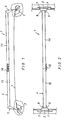
- Fig. 1 is a front view of a roof rack section 1 mounted on a vehicle roof 3.
- the roof 3 is however only at the ends of the section 1 illustrated in the form of cut-away cross sections.
- the section 1 includes a crossbeam 4 extending over the roof 3 in the transverse direction of the vehicle. Downwardly extending feet 5 are welded to either end of the crossbeam 4. Both feet 5 are symmetrically the same and the description is therefore limited to one of them.
- Each foot 5 comprises an end plate 2 shaped like an isosceles triangle and two cheeks 6 which are welded onto one end of the crossbeam 4 and form a substantially symmetrical support means. There is thus obtained a strong and stiff connection between the foot 5 and the crossbeam 4.
- the lower part of the foot 5 is provided with two inwardly directed pins 7 which are suitably welded to the end plate 2 at a spacing which is greater than half the height of the end plate 2.
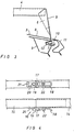
- Fig. 3 illustrates how an inventively implemented foot 5 is intended to be fitted to the vehicle roof 3.
- the vehicle roof 3 includes a roof sheet 8 welded to a stringer 9 extending in the longitudinal direction of the vehicle.
- the roof sheet 8 and the stringer 9 are formed with a longitudinal exterior drip moulding 10 which is substantially covered by the upper part of a closed vehicle door 11 which is partly illustrated in Fig. 3.
- a plurality of holes are provided in the sheet 8 and the stringer 9, flanged bushes 13 being pressed into the holes.
- the spacing of the holes corresponds to the spacing of the pins 7 of the foot 5, and each bush 13 is dimensioned for accommodating such a pin 7.
- the crossbeam 4 When the roof rack section 1 is fitted to a vehicle, the crossbeam 4 is intended to extend transverse the vehicle roof 3.
- the crossbeam 4 is formed with two telescopically joined beam portions 14, 15.
- the right-hand beam portion 14 is provided with a uniform cross section, while the left-hand portion 15 is formed with a reduced cross section at its free end portion such as to glide into the right-hand portion 14.
- Both beam portions 14, 15 are preferably made from square tubing, the left-hand portion 15 being adapted for fitting telescopically into the right-hand portion 14. Both portions have approximately the same length, whereby the middle region of the crossbeam 4 is given higher supporting strength.
- both portions 14, 15 can be locked to each other in different relative positions with the aid of a locking means, suitably a toggle latch 16, arranged approximately at the middle of the crossbeam 4.
- a locking means suitably a toggle latch 16, arranged approximately at the middle of the crossbeam 4.
- a U-shaped lever 18 is pivotably mounted at its fulcrum in a mounting 17 welded to one portion 14.
- a tee-bolt 19 is pivotably mounted in the legs of the U-shaped lever 18, the end of the tee-bolt 19 being screwed into a nut on a tensioning plate 20 provided with a bent-over lip for engaging in a recess 21 in the other crossbeam portion 15.
- the tensioning plate 20 can urge the crossbeam portions 14, 15 into telescopic contraction when the lever 18 is swung towards the half 14, thus enabling the pins 7 on the feet 5 to engage in their bushes in the holes in the vehicle body.
- the lever 18 engages a lug 22 which is rigidly attached to the crossbeam portion 14.
- the lug 22 is preferably shaped to enable a safety pin or an ordinary padlock to secure the section in a fitted position and to prevent unintentional release.
- the locking and tensioning means for the feet can thus be given another embodiment, enabling simple tensional clamping of the roof rack section.
- the crossbeam may, for example, be implemented such that one of its two portions constitutes the chief length of the crossbeam with its free end displaceably mounted in the free end of the shorter portion.
- the displaceable portion and its foot can then be clamped with the aid of a screwjoint or the like, which extends in the longitudinal direction of the crossbeam and which is preferably located within the crossbeam. Guiding the displaceable portion relative the other portion can be achieved with the aid of sliding guides or the like.
Landscapes
- Engineering & Computer Science (AREA)
- Mechanical Engineering (AREA)
- Fittings On The Vehicle Exterior For Carrying Loads, And Devices For Holding Or Mounting Articles (AREA)
Claims (8)
Applications Claiming Priority (2)
| Application Number | Priority Date | Filing Date | Title |
|---|---|---|---|
| SE8303535A SE450561B (sv) | 1983-06-20 | 1983-06-20 | Lastbygel for fordon |
| SE8303535 | 1983-06-20 |
Publications (3)
| Publication Number | Publication Date |
|---|---|
| EP0129524A2 EP0129524A2 (fr) | 1984-12-27 |
| EP0129524A3 EP0129524A3 (en) | 1986-03-26 |
| EP0129524B1 true EP0129524B1 (fr) | 1988-03-09 |
Family
ID=20351691
Family Applications (1)
| Application Number | Title | Priority Date | Filing Date |
|---|---|---|---|
| EP84850185A Expired EP0129524B1 (fr) | 1983-06-20 | 1984-06-14 | Section de galerie pour un véhicule |
Country Status (5)
| Country | Link |
|---|---|
| US (1) | US4627559A (fr) |
| EP (1) | EP0129524B1 (fr) |
| JP (1) | JPS6012354A (fr) |
| DE (2) | DE3469709D1 (fr) |
| SE (1) | SE450561B (fr) |
Families Citing this family (16)
| Publication number | Priority date | Publication date | Assignee | Title |
|---|---|---|---|---|
| DE3526639C2 (de) * | 1985-07-25 | 1994-12-01 | Evelyn Konopka Kunststoffverar | Dachständereinheit |
| JPH08518B2 (ja) * | 1985-08-15 | 1996-01-10 | 日産自動車株式会社 | 自動車のルーフ構造 |
| SE455589B (sv) * | 1987-01-12 | 1988-07-25 | Thule Ind Ab | Festanordning for en for ett fordonstak avsedd lastanordning |
| US5002216A (en) * | 1987-07-16 | 1991-03-26 | Gerber Group Ltd. | Invisible mount roof rack |
| US4858803A (en) * | 1987-07-16 | 1989-08-22 | Gerber Group, Ltd. | Invisible mount roof rack |
| DE3832867A1 (de) * | 1988-09-28 | 1990-04-05 | Opel Adam Ag | Dachlasttraeger fuer ein kraftfahrzeug |
| JPH02117239U (fr) * | 1989-03-08 | 1990-09-19 | ||
| SE470181B (sv) * | 1991-09-09 | 1993-11-29 | Thule Ind Ab | Anordning vid lastbärarfot |
| US5267681A (en) * | 1992-01-30 | 1993-12-07 | Ski Tote, U.S.A. | Utility rack anchor |
| FR2690888B1 (fr) * | 1992-05-06 | 1996-09-13 | Farnier & Penin | Porte-bagages pour vehicules automobile. |
| GB2267261A (en) * | 1992-05-26 | 1993-12-01 | David Tonks | Collapsible roof rack |
| FR2820380B1 (fr) * | 2001-02-02 | 2003-12-12 | Scambia Ind Dev Ag | Vehicule automobile avec au moins une barre de toit |
| US20060000860A1 (en) * | 2004-06-30 | 2006-01-05 | Pieciak Kenneth F | Rack mount assembly for vehicle roof racks |
| US20060273121A1 (en) * | 2005-06-02 | 2006-12-07 | Thomas George E | Light bar mounting assembly for emergency vehicles |
| EP2301806B1 (fr) * | 2009-09-24 | 2012-12-26 | Thule Sweden AB | Support de pied de porteur de charge, pied de porteur de charge et procédé de fabrication du support de pied de porteur de charge |
| EP3856572B1 (fr) * | 2018-11-13 | 2024-07-03 | Rivian IP Holdings, LLC | Barre transversale extensible pour un véhicule |
Family Cites Families (9)
| Publication number | Priority date | Publication date | Assignee | Title |
|---|---|---|---|---|
| FR990734A (fr) * | 1949-04-26 | 1951-09-25 | Galerie porte-bagage à fixation rapide | |
| AT202473B (de) * | 1957-11-02 | 1959-03-10 | Peter Weninger | Kraftfahrzeugauflage |
| FR1489192A (fr) * | 1966-06-09 | 1967-07-21 | Porte-skis | |
| US3385488A (en) * | 1967-03-31 | 1968-05-28 | Bronson Joseph | Clamping device |
| DE2551646C2 (de) * | 1975-11-18 | 1986-11-27 | Fa. Heinrich Eckel, 8000 München | Bügelförmiger Lastträger zur Befestigung an einem Fahrzeugdach |
| DE2908682A1 (de) * | 1979-03-06 | 1980-09-11 | Daimler Benz Ag | Befestigungsvorrichtung fuer dachtraeger am dach von insbesondere personenkraftwagen |
| DE3003216A1 (de) * | 1980-01-30 | 1981-08-06 | Ford-Werke AG, 5000 Köln | Kraftfahrzeugkarosserie mit verdeckter regenrinnenanordnung |
| DE3013649A1 (de) * | 1980-04-09 | 1981-10-15 | Audi Nsu Auto Union Ag, 7107 Neckarsulm | Kraftfahrzeug mit einem dachgepaecktraeger |
| DE3032099A1 (de) * | 1980-08-26 | 1982-04-01 | Daimler-Benz Ag, 7000 Stuttgart | Mit abstand von dachhaut eines kraftwagens, insbesondere eines personenkraftwagens angeordneter dachlasttraeger |
-
1983
- 1983-06-20 SE SE8303535A patent/SE450561B/sv not_active IP Right Cessation
-
1984
- 1984-06-14 EP EP84850185A patent/EP0129524B1/fr not_active Expired
- 1984-06-14 DE DE8484850185T patent/DE3469709D1/de not_active Expired
- 1984-06-14 DE DE198484850185T patent/DE129524T1/de active Pending
- 1984-06-19 US US06/622,249 patent/US4627559A/en not_active Expired - Lifetime
- 1984-06-19 JP JP59126301A patent/JPS6012354A/ja active Pending
Also Published As
| Publication number | Publication date |
|---|---|
| EP0129524A2 (fr) | 1984-12-27 |
| SE450561B (sv) | 1987-07-06 |
| SE8303535L (sv) | 1984-12-21 |
| EP0129524A3 (en) | 1986-03-26 |
| DE129524T1 (de) | 1985-08-14 |
| JPS6012354A (ja) | 1985-01-22 |
| SE8303535D0 (sv) | 1983-06-20 |
| US4627559A (en) | 1986-12-09 |
| DE3469709D1 (en) | 1988-04-14 |
Similar Documents
| Publication | Publication Date | Title |
|---|---|---|
| EP0129524B1 (fr) | Section de galerie pour un véhicule | |
| US5464140A (en) | Mounting structure for roof rack support members | |
| US5427487A (en) | Cargo stabilizer for pickup trucks | |
| US9371041B2 (en) | Load carrier foot and a roof rack | |
| US5104020A (en) | Apparatus for carrying a load | |
| US4772165A (en) | Load restraining apparatus for vehicles | |
| US6059159A (en) | Utility rack adapter bracket | |
| EP3594065B1 (fr) | Support de charge | |
| EP0130663B1 (fr) | Pièce d'attache captive pour bois d'arrimage | |
| US4138046A (en) | Demountable truck bed load-supporting rack | |
| US9248784B2 (en) | Truck crossbar attachment | |
| US4988026A (en) | Discretely adjustable support rail for luggage carriers | |
| US5282562A (en) | Vehicle roof-top support rack with permanent attachment bases | |
| US4606432A (en) | Adjustable ladder leg | |
| US20230398946A1 (en) | Rear load carrier, clamping device and system | |
| US6176657B1 (en) | Cargo restraint assembly for a vehicle cargo bed | |
| EP4289676B1 (fr) | Support de roue arrière, module d'extension et support de charge arrière | |
| US6632055B2 (en) | Payload holder | |
| EP1688304B1 (fr) | Porte-charge pour galerie fixe de toit | |
| US3523669A (en) | Holding device for attachment to slotted track means | |
| GB2347402A (en) | Roof structure for a vehicle | |
| US4412615A (en) | Engine cradle | |
| EP0310204A1 (fr) | Porte-change pour fixation détachable sur la partie fixe d'une attache d'attelage amovible | |
| US11034392B2 (en) | Apparatus for mounting on a vehicle and for transporting materials, equipment, and gear | |
| US3104860A (en) | figure |
Legal Events
| Date | Code | Title | Description |
|---|---|---|---|
| PUAI | Public reference made under article 153(3) epc to a published international application that has entered the european phase |
Free format text: ORIGINAL CODE: 0009012 |
|
| AK | Designated contracting states |
Designated state(s): DE FR GB IT |
|
| EL | Fr: translation of claims filed | ||
| ITCL | It: translation for ep claims filed |
Representative=s name: STUDIO TORTA SOCIETA' SEMPLICE |
|
| DET | De: translation of patent claims | ||
| PUAL | Search report despatched |
Free format text: ORIGINAL CODE: 0009013 |
|
| AK | Designated contracting states |
Kind code of ref document: A3 Designated state(s): DE FR GB IT |
|
| 17P | Request for examination filed |
Effective date: 19860911 |
|
| 17Q | First examination report despatched |
Effective date: 19870722 |
|
| GRAA | (expected) grant |
Free format text: ORIGINAL CODE: 0009210 |
|
| AK | Designated contracting states |
Kind code of ref document: B1 Designated state(s): DE FR GB IT |
|
| REF | Corresponds to: |
Ref document number: 3469709 Country of ref document: DE Date of ref document: 19880414 |
|
| ET | Fr: translation filed | ||
| ITF | It: translation for a ep patent filed | ||
| PLBE | No opposition filed within time limit |
Free format text: ORIGINAL CODE: 0009261 |
|
| STAA | Information on the status of an ep patent application or granted ep patent |
Free format text: STATUS: NO OPPOSITION FILED WITHIN TIME LIMIT |
|
| 26N | No opposition filed | ||
| ITTA | It: last paid annual fee | ||
| REG | Reference to a national code |
Ref country code: GB Ref legal event code: IF02 |
|
| PGFP | Annual fee paid to national office [announced via postgrant information from national office to epo] |
Ref country code: FR Payment date: 20020610 Year of fee payment: 19 |
|
| PGFP | Annual fee paid to national office [announced via postgrant information from national office to epo] |
Ref country code: GB Payment date: 20020612 Year of fee payment: 19 |
|
| PGFP | Annual fee paid to national office [announced via postgrant information from national office to epo] |
Ref country code: DE Payment date: 20020619 Year of fee payment: 19 |
|
| PG25 | Lapsed in a contracting state [announced via postgrant information from national office to epo] |
Ref country code: GB Free format text: LAPSE BECAUSE OF NON-PAYMENT OF DUE FEES Effective date: 20030614 |
|
| PG25 | Lapsed in a contracting state [announced via postgrant information from national office to epo] |
Ref country code: DE Free format text: LAPSE BECAUSE OF NON-PAYMENT OF DUE FEES Effective date: 20040101 |
|
| GBPC | Gb: european patent ceased through non-payment of renewal fee |
Effective date: 20030614 |
|
| PG25 | Lapsed in a contracting state [announced via postgrant information from national office to epo] |
Ref country code: FR Free format text: LAPSE BECAUSE OF NON-PAYMENT OF DUE FEES Effective date: 20040227 |
|
| REG | Reference to a national code |
Ref country code: FR Ref legal event code: ST |