EP0129878A2 - Ultraschallkopf mit einem zweifach bewegbaren Wandler - Google Patents
Ultraschallkopf mit einem zweifach bewegbaren Wandler Download PDFInfo
- Publication number
- EP0129878A2 EP0129878A2 EP84107190A EP84107190A EP0129878A2 EP 0129878 A2 EP0129878 A2 EP 0129878A2 EP 84107190 A EP84107190 A EP 84107190A EP 84107190 A EP84107190 A EP 84107190A EP 0129878 A2 EP0129878 A2 EP 0129878A2
- Authority
- EP
- European Patent Office
- Prior art keywords
- transducer
- drive shaft
- ultrasonic probe
- motion
- housing
- Prior art date
- Legal status (The legal status is an assumption and is not a legal conclusion. Google has not performed a legal analysis and makes no representation as to the accuracy of the status listed.)
- Granted
Links
Images

Classifications
-
- G—PHYSICS
- G10—MUSICAL INSTRUMENTS; ACOUSTICS
- G10K—SOUND-PRODUCING DEVICES; METHODS OR DEVICES FOR PROTECTING AGAINST, OR FOR DAMPING, NOISE OR OTHER ACOUSTIC WAVES IN GENERAL; ACOUSTICS NOT OTHERWISE PROVIDED FOR
- G10K11/00—Methods or devices for transmitting, conducting or directing sound in general; Methods or devices for protecting against, or for damping, noise or other acoustic waves in general
- G10K11/18—Methods or devices for transmitting, conducting or directing sound
- G10K11/26—Sound-focusing or directing, e.g. scanning
- G10K11/35—Sound-focusing or directing, e.g. scanning using mechanical steering of transducers or their beams
- G10K11/352—Sound-focusing or directing, e.g. scanning using mechanical steering of transducers or their beams by moving the transducer
-
- A—HUMAN NECESSITIES
- A61—MEDICAL OR VETERINARY SCIENCE; HYGIENE
- A61C—DENTISTRY; APPARATUS OR METHODS FOR ORAL OR DENTAL HYGIENE
- A61C9/00—Impression cups, i.e. impression trays; Impression methods
- A61C9/004—Means or methods for taking digitized impressions
- A61C9/0046—Data acquisition means or methods
- A61C9/0086—Acoustic means or methods
-
- A—HUMAN NECESSITIES
- A61—MEDICAL OR VETERINARY SCIENCE; HYGIENE
- A61B—DIAGNOSIS; SURGERY; IDENTIFICATION
- A61B8/00—Diagnosis using ultrasonic, sonic or infrasonic waves
- A61B8/42—Details of probe positioning or probe attachment to the patient
- A61B8/4272—Details of probe positioning or probe attachment to the patient involving the acoustic interface between the transducer and the tissue
- A61B8/4281—Details of probe positioning or probe attachment to the patient involving the acoustic interface between the transducer and the tissue characterised by sound-transmitting media or devices for coupling the transducer to the tissue
Definitions
- This invention relates to mechanically scanned ultrasonic probe.
- the invention is particularly useful for dental applications.
- a mechanically scanned ultrasonic diagnostic probe for use in dental clinics is shown and described in Japanese Laid-open Patent Publication 58-185139 (published October 28, 1983).
- This ultrasonic probe includes a mechanism by which an ultrasonic transducer is arranged to swing about a drive shaft to steer the acoustic beam in a sector plane.
- Is is therefore an object of the present invention to provide an ultrasonic probe capable of generating acoustic data on three dimensions of an object under examination.
- This object is attained by the provision of a dual motion drive mechanism located at one end of an elongated housing and a linkage that transmits the dual motion to an ultrasonic transducer located at the other end of the housing. Acoustic beam transmitted by the transducer is steered in orthogonal directions.
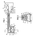
- the probe is generally in the shape of a toothbrush and comprises a transducer section 1 and a dual motion drive section 2.
- Transducer section 1 is encased in a housing 3 having a downwardly flared, head portion 3a which accommodates an ultrasonic transducer 4 and a hollow arm portion 3b connected to the drive section 2.
- the arm portion 3b has a sufficient length to allow the head portion to reach the innermost part of the patient's teeth.
- Dual motion drive section 1 is encased in a housing 5 which accommodates a dual motion drive mechanism.
- the housing 5 serves as a hand grip portion of the probe.
- transducer 1 comprises an array of piezoelectric elements for emitting an acoustic beam 6 into an object 7 or teeth under examination when excited by drive pulses.
- the drive pulses are mutually phase-shifted so that the acoustic energies transmitted individually from the piezoelectric elements form an intensified narrow beam.
- the transducer also acts as a sensor during receive mode for converting echos from the object 7 to an electrical signal.
- Transducer 4 is rotatably mounted by a pin 8 on the free end of a drive shaft 9.
- An arcuate guide arm 10 extends from one inner side wall of the housing portion 3a through an opening 4a of transducer 1 to the other inner side wall so that transducer 4 is swingable about guide arm 10 in a first plane and is further swingable about the axis of drive shaft 9 in a second plane normal to the first plane.
- Head portion 3a has a lower open end sealed fluid-tightly with a diaphragm 11 of a material which is transparent to acoustic energy and is flexible enough to take the shape of human teeth.
- Head portion 3a is partially filled with liquid 12 in which the energy radiating face of transducer 4 is submerged.
- Liquid 12 is of a material which allows acoustic energy to propagate with a minimum loss and which provides acoustic impedance match between the transducer and object.
- One suitable material for the liquid is water.
- Liquid 2 is contained by a sealing member 13 which provides fluid-tight sealing between the housing's inner walls and the side walls of transducer 4. To permit transducer 4 to swing in the orthogonal directions, sealing member 13 is flexible and preferably formed into a corrugated, bellows-like shape.
- the dual motion drive comprises a first micromotor 14 with its rotor shaft firmly coupled to a swash-plate cam 15 having its cam face in camming contact with a proximal end of drive shaft 9.
- a second micromoter 16 drives an eccentric cam 17 which translates the rotary motion to a swing motion, the latter being transmitted by a friction wheel 18 to a friction wheel 19 which is fixedly mounted on drive shaft 9.
- a potentiometer or angle sensor 20 is coupled to the shaft of motor 14.
- the cam shaft of cam 17 is coupled by a similar potentiometer 21 to the friction wheel 18.
- Drive shaft 9 therefore provides reciprocating and swing motions and transducer 4 swings about guide arm 10 in response to the reciprocation of drive shaft 9 and further swings about the axis of drive shaft 9 in response to the swing of the latter.
- the acoustic beam is thus steerablein a first sector plane parallel to the axis of drive shaft 9 and in a second sector plane normal to the first sector plane.
- the beam is steered along each of a plurality of scan lines and successively shifted to the next scan line as in a raster format. Three-dimensional diagnostic information is therefore obtained. The need for manually repositioning the probe is eliminated.
- the orthogonal swing motions of the transducer permits it to be encased in a small space which advatangeously reduces the probe size.
- Figs. 3 to 7 are illustrations of various modifications of the present invention in which parts corresponding to those in Figs. 1 and 2 are marked with the same numerals and the description thereof are omitted for brevity.
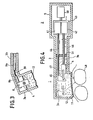
- the head portion 3a is preferably bent with respect to the arm portion 3b as shown in Fig. 3. This is accomplished by dividing the drive shaft 9 into a shaft 9a connected to the drive section 2 and a shaft 9b swingably carrying the transducer 4 and coupling the shafts 9a and 9b by a flexible joint 30 such as flexible cable or universal joint.
- acoustic energy be always directed toward the center of a tooth as the point of scan is shifted along the curvature of the tooth.
- This is accomplished by an embodiment shown in Fig. 4.
- This embodiment comprises a linear motor 41 and a rotary drive 42 which are fixedly mounted on a carriage 43.
- the rotary drive 42 includes a rotary motor and a cam arrangement that translates the rotary motion to a swing motion.
- This carriage is reciprocably moved by means of a common linear motor 40 to reciprocate transducer 4 across elongated acoustic window ll.
- the output shaft of linear motor 41 is connected to one end of a drive shaft 44, the other end of which is in abutment with an acoustic reflector 45.
- the output shaft of rotary motor 42 is fixedly connected by a drive shaft 46 to transducer 4.
- Transducer 4 has a pair of arms 47 between which the reflector 45 is pivotably mounted and urged clockwise by a spring, not shown, toward drive shaft 44.
- the energy emitted from transducer 4 is reflected by reflector 45 toward the center of a tooth 48. All the components are encased in a toothbrush-like housing 49. Housing 49 is filled to a point halfway of its arm portion and fluid-tightly contained by a sealing member 51.
- Transducer 4 and reflector 45 are caused to reciprocate by the common linear motor 40 and are rotated by swing motion drive 42, whereby the beam is scanned along a path parallel with the vertical axis of the tooth 48 in response to the swing motion and shifted to the next path in response to a displacement in the reciprocation.
- drive shaft 44 Since drive shaft 44 is driven by linear motor 41 as well as by the common linear motor 40, it reciprocates slightly higher than the reciprocation of drive shaft 46. As a result, the angle of inclination of reflector 45 is varied as a function of distance away from the drive section so that the beam reflected upon it is automatically oriented toward the center of tooth 48 as indicated by chain-dot lines in Fig. 4.
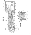
- FIG. 5 and 6 An embodiment shown in Figs. 5 and 6 is a further preferred form of the present invention.
- the transducer's point of swing on the first plane coincides with its point of swing on the second plane. This coincidence is advantageous for the design of scan converters. This is accomplished by the provision of separate drive mechanisms for swing motion and reciprocation.
- swing motion is provided by a rotary motor 60 which drives eccentric cam 61 which translates the rotary motion to a swing motion, the latter being transmitted via friction wheels 62, 63 to a rotary drive shaft 64.
- Reciprocating motion is provided by a rotary motor 65 having its output fixedly coupled to swash-plate cam 66.
- a linear drive shaft 67 has its read end in contact with the cam face of the swash plate.
- Drive shafts 64 and 67 are journalled through a pair of supports 74 and 75.
- Rotary drive shaft 64 is fixedly connected to the web portion of a first U-shaped support 68.
- Transducer 4 is pivotally mounted on support 68 by a pair of trunnions 69 which intersect the axis 78 of rotary drive shaft 64 as shown in Fig. 6.
- Linear drive shaft 67 is, on the other hand, connected by a pin 70 to one of a pair of side upright members 71 which form a second, generally U-shaped member with a rectangular frame member 72 in which the lower part of transducer 4 is positioned.
- the frame member 72 has a sufficient space therein in the transverse direction of the housing to give a desired swing motion to transducer 4.
- Upright members 71 are pivotally mounted by trunnions 73 to opposite inner side walls of the head portion 3a.
- the transducer section 1 of the probe is separated by a sealing member 76 from the drive section 2 and the transducer section 1 is filled with liquid 12.
- transducer 4 swings about axis 78 in response to the swing motion of rotary shaft 64.
- the reciprocating motion of linear drive shaft 67 causes frame member 72 to swing about trunnions 73 forcing transducer 4 to swing about trunnions 69. Since trunnions 69 coincide with the rotary axis 78, the transducer swings about a single pivot point in either direction of its orthogonal motions.
- swash-plate cam 66 is submerged in liquid 12. This reduces pressure variation in liquid 12 which would otherwise occur as a result of the reciprocation of shaft 67.
- FIG. 7 A further embodiment of the present invention is illustrated in Fig. 7.
- This embodiment fascilitates servicing by making transducer section 1 and drive section 2 detatchable from each other.
- Housing 5 of the drive section is secured by screws 80 to a flange 81 which forms part of the arm portion 3b.
- Dual motion drive mechanism 82 has an output shaft 83 fixed to an open-ended cylinder 84.
- Transducer 4 is attached to a front end of a hollow drive shaft 85 whose rear end is snuggly and detatchably engaged into the opening of cylinder 84 by a flexible ring 86.
- a signal transmission cable 87 extends from transducer 4 through drive shaft 85 to a connector 88 which connects the cable with a second cable 89 leading to control circuitry.
- a sealing member 90 is provided to contain liquid 12 in the head portion 3a. Head portion 3a is cemented to the front end of arm portion 3b.
Landscapes
- Physics & Mathematics (AREA)
- Acoustics & Sound (AREA)
- Health & Medical Sciences (AREA)
- Multimedia (AREA)
- Engineering & Computer Science (AREA)
- Life Sciences & Earth Sciences (AREA)
- Epidemiology (AREA)
- Animal Behavior & Ethology (AREA)
- General Health & Medical Sciences (AREA)
- Public Health (AREA)
- Veterinary Medicine (AREA)
- Dentistry (AREA)
- Oral & Maxillofacial Surgery (AREA)
- Ultra Sonic Daignosis Equipment (AREA)
Applications Claiming Priority (6)
| Application Number | Priority Date | Filing Date | Title |
|---|---|---|---|
| JP113707/83 | 1983-06-23 | ||
| JP58113707A JPS605132A (ja) | 1983-06-23 | 1983-06-23 | 超音波探触子 |
| JP58178529A JPS6068835A (ja) | 1983-09-27 | 1983-09-27 | 超音波探触子 |
| JP178529/83 | 1983-09-27 | ||
| JP58229310A JPS60119932A (ja) | 1983-12-05 | 1983-12-05 | 超音波探触子 |
| JP229310/83 | 1983-12-05 |
Publications (3)
| Publication Number | Publication Date |
|---|---|
| EP0129878A2 true EP0129878A2 (de) | 1985-01-02 |
| EP0129878A3 EP0129878A3 (en) | 1985-09-11 |
| EP0129878B1 EP0129878B1 (de) | 1989-01-11 |
Family
ID=27312566
Family Applications (1)
| Application Number | Title | Priority Date | Filing Date |
|---|---|---|---|
| EP84107190A Expired EP0129878B1 (de) | 1983-06-23 | 1984-06-22 | Ultraschallkopf mit einem zweifach bewegbaren Wandler |
Country Status (3)
| Country | Link |
|---|---|
| US (1) | US4637256A (de) |
| EP (1) | EP0129878B1 (de) |
| DE (1) | DE3476132D1 (de) |
Cited By (8)
| Publication number | Priority date | Publication date | Assignee | Title |
|---|---|---|---|---|
| WO1989003195A1 (en) * | 1987-10-14 | 1989-04-20 | Hollming Oy | Ultrasound method and apparatus for examining dense tissues in particular |
| EP0504480A3 (en) * | 1991-03-20 | 1993-03-03 | Olympus Optical Co., Ltd | Ultrasonic diagnostic apparatus using a linear and angular scanning probe |
| US5247938A (en) * | 1990-01-11 | 1993-09-28 | University Of Washington | Method and apparatus for determining the motility of a region in the human body |
| US5373849A (en) * | 1993-01-19 | 1994-12-20 | Cardiovascular Imaging Systems, Inc. | Forward viewing imaging catheter |
| EP0871401A4 (de) * | 1995-02-15 | 2000-12-20 | Ultra Scan Corp | System zur biometrischen ultraschall-bilderzeugung und zur identitätsverifizierung |
| CN100566663C (zh) * | 2007-06-01 | 2009-12-09 | 深圳市德力凯电子有限公司 | 一种脑血流检测探头架 |
| WO2014107427A1 (en) | 2013-01-04 | 2014-07-10 | Muffin Incorporated | Reciprocating ultrasound device |
| US10595823B2 (en) | 2013-03-15 | 2020-03-24 | Muffin Incorporated | Internal ultrasound assembly fluid seal |
Families Citing this family (85)
| Publication number | Priority date | Publication date | Assignee | Title |
|---|---|---|---|---|
| US4722345A (en) * | 1984-11-09 | 1988-02-02 | Matsushita Electric Industrial Co., Ltd. | Ultrasonic diagnostic multiple-sector image display system |
| US4932414A (en) * | 1987-11-02 | 1990-06-12 | Cornell Research Foundation, Inc. | System of therapeutic ultrasound and real-time ultrasonic scanning |
| US4917096A (en) * | 1987-11-25 | 1990-04-17 | Laboratory Equipment, Corp. | Portable ultrasonic probe |
| IL87316A (en) * | 1988-08-02 | 1992-08-18 | Elscint Ltd | Multi-planar scanning mechanism |
| DE3914619A1 (de) * | 1989-05-03 | 1990-11-08 | Kontron Elektronik | Vorrichtung zur transoesophagealen echokardiographie |
| DE69027284T2 (de) * | 1989-12-14 | 1996-12-05 | Aloka Co Ltd | Dreidimensionaler Ultraschallabtaster |
| US5207225A (en) * | 1990-11-14 | 1993-05-04 | Advanced Technology Laboratories, Inc. | Transesophageal ultrasonic scanhead |
| JP2715762B2 (ja) * | 1990-11-30 | 1998-02-18 | 富士写真光機株式会社 | 超音波検査装置 |
| US5255684A (en) * | 1991-10-25 | 1993-10-26 | Interspec, Inc. | Ultrasonic probe assembly |
| JPH0773576B2 (ja) * | 1992-05-27 | 1995-08-09 | アロカ株式会社 | 三次元データ取込み用超音波探触子 |
| US5456256A (en) * | 1993-11-04 | 1995-10-10 | Ultra-Scan Corporation | High resolution ultrasonic imaging apparatus and method |
| US5450851A (en) * | 1994-05-25 | 1995-09-19 | Advanced Technology Laboratories, Inc. | Ultrasonic probe assembly |
| US5518008A (en) * | 1994-08-25 | 1996-05-21 | Spectral Sciences Research Corporation | Structural analyzer, in particular for medical implants |
| US5487388A (en) * | 1994-11-01 | 1996-01-30 | Interspec. Inc. | Three dimensional ultrasonic scanning devices and techniques |
| DE19602686A1 (de) * | 1995-01-26 | 1996-08-08 | Storz Medical Ag | Vorrichtung zur Behandlung von Zähnen |
| IL119701A0 (en) * | 1996-11-26 | 1997-02-18 | Novadent Ltd | Device and method for the ultrasonic detection of dental caries |
| US6050943A (en) * | 1997-10-14 | 2000-04-18 | Guided Therapy Systems, Inc. | Imaging, therapy, and temperature monitoring ultrasonic system |
| US6036646A (en) * | 1998-07-10 | 2000-03-14 | Guided Therapy Systems, Inc. | Method and apparatus for three dimensional ultrasound imaging |
| US7914453B2 (en) | 2000-12-28 | 2011-03-29 | Ardent Sound, Inc. | Visual imaging system for ultrasonic probe |
| US6634234B1 (en) * | 2001-02-10 | 2003-10-21 | Vega Grieshaber Kg | Adjustable measurement head and a level measurement device and method employing it |
| CN1812751B (zh) * | 2003-06-27 | 2011-11-16 | 皇家飞利浦电子股份有限公司 | 采用声波作用进行牙齿净化的电动牙刷 |
| US7285093B2 (en) * | 2003-10-10 | 2007-10-23 | Imadent Ltd. | systems for ultrasonic imaging of a jaw, methods of use thereof and coupling cushions suited for use in the mouth |
| US7393325B2 (en) | 2004-09-16 | 2008-07-01 | Guided Therapy Systems, L.L.C. | Method and system for ultrasound treatment with a multi-directional transducer |
| US7824348B2 (en) | 2004-09-16 | 2010-11-02 | Guided Therapy Systems, L.L.C. | System and method for variable depth ultrasound treatment |
| US9011336B2 (en) * | 2004-09-16 | 2015-04-21 | Guided Therapy Systems, Llc | Method and system for combined energy therapy profile |
| US10864385B2 (en) | 2004-09-24 | 2020-12-15 | Guided Therapy Systems, Llc | Rejuvenating skin by heating tissue for cosmetic treatment of the face and body |
| US8535228B2 (en) | 2004-10-06 | 2013-09-17 | Guided Therapy Systems, Llc | Method and system for noninvasive face lifts and deep tissue tightening |
| US8444562B2 (en) | 2004-10-06 | 2013-05-21 | Guided Therapy Systems, Llc | System and method for treating muscle, tendon, ligament and cartilage tissue |
| US7530958B2 (en) * | 2004-09-24 | 2009-05-12 | Guided Therapy Systems, Inc. | Method and system for combined ultrasound treatment |
| WO2006042168A1 (en) * | 2004-10-06 | 2006-04-20 | Guided Therapy Systems, L.L.C. | Method and system for controlled thermal treatment of human superficial tissue |
| US7758524B2 (en) | 2004-10-06 | 2010-07-20 | Guided Therapy Systems, L.L.C. | Method and system for ultra-high frequency ultrasound treatment |
| US8690779B2 (en) | 2004-10-06 | 2014-04-08 | Guided Therapy Systems, Llc | Noninvasive aesthetic treatment for tightening tissue |
| US7530356B2 (en) * | 2004-10-06 | 2009-05-12 | Guided Therapy Systems, Inc. | Method and system for noninvasive mastopexy |
| WO2006042163A2 (en) * | 2004-10-06 | 2006-04-20 | Guided Therapy Systems, L.L.C. | Method and system for cosmetic enhancement |
| US9827449B2 (en) | 2004-10-06 | 2017-11-28 | Guided Therapy Systems, L.L.C. | Systems for treating skin laxity |
| KR20170117205A (ko) | 2004-10-06 | 2017-10-20 | 가이디드 테라피 시스템스, 엘.엘.씨. | 초음파 치료 시스템 |
| US8133180B2 (en) | 2004-10-06 | 2012-03-13 | Guided Therapy Systems, L.L.C. | Method and system for treating cellulite |
| US11235179B2 (en) | 2004-10-06 | 2022-02-01 | Guided Therapy Systems, Llc | Energy based skin gland treatment |
| US11883688B2 (en) | 2004-10-06 | 2024-01-30 | Guided Therapy Systems, Llc | Energy based fat reduction |
| US9694212B2 (en) | 2004-10-06 | 2017-07-04 | Guided Therapy Systems, Llc | Method and system for ultrasound treatment of skin |
| US20060111744A1 (en) | 2004-10-13 | 2006-05-25 | Guided Therapy Systems, L.L.C. | Method and system for treatment of sweat glands |
| US11724133B2 (en) | 2004-10-07 | 2023-08-15 | Guided Therapy Systems, Llc | Ultrasound probe for treatment of skin |
| US11207548B2 (en) | 2004-10-07 | 2021-12-28 | Guided Therapy Systems, L.L.C. | Ultrasound probe for treating skin laxity |
| US20060270935A1 (en) * | 2005-03-31 | 2006-11-30 | Perioimaging, Inc. | Ultrasonic periodontal device and method of using |
| EP2533130A1 (de) | 2005-04-25 | 2012-12-12 | Ardent Sound, Inc. | Verfahren und System zur Verbesserung der peripheren Computersicherheit |
| US9566454B2 (en) * | 2006-09-18 | 2017-02-14 | Guided Therapy Systems, Llc | Method and sysem for non-ablative acne treatment and prevention |
| EP2152351B1 (de) | 2007-05-07 | 2016-09-21 | Guided Therapy Systems, L.L.C. | Verfahren und systeme zur modulierung von medikamenten mit akustischer energie |
| EP2152167B1 (de) * | 2007-05-07 | 2018-09-05 | Guided Therapy Systems, L.L.C. | Verfahren und systeme zur kopplung und fokussierung von akustischer energie mit einem kopplungselement |
| US20150174388A1 (en) | 2007-05-07 | 2015-06-25 | Guided Therapy Systems, Llc | Methods and Systems for Ultrasound Assisted Delivery of a Medicant to Tissue |
| KR102746886B1 (ko) | 2008-06-06 | 2024-12-27 | 얼테라, 인크 | 초음파 치료 시스템 |
| US12102473B2 (en) | 2008-06-06 | 2024-10-01 | Ulthera, Inc. | Systems for ultrasound treatment |
| CA2733261A1 (en) * | 2008-08-05 | 2010-02-11 | Us Hifu, Llc | Hifu treatment probe |
| EP2382010A4 (de) | 2008-12-24 | 2014-05-14 | Guided Therapy Systems Llc | Verfahren und systeme zur fettreduzierung und/oder behandlung von cellulite |
| US9351702B2 (en) * | 2009-02-02 | 2016-05-31 | Noble Sensors, Llc | Ultrasonic scanning probe with a tuning fork-type oscillator and feedback control thereof |
| US10603008B2 (en) * | 2009-02-19 | 2020-03-31 | Tessonics Corporation | Ultrasonic device for assessment of internal tooth structure |
| DE102009046146A1 (de) * | 2009-10-29 | 2011-05-12 | Robert Bosch Gmbh | Ultraschallwandler zum Einsatz in einem fluiden Medium |
| US8715186B2 (en) | 2009-11-24 | 2014-05-06 | Guided Therapy Systems, Llc | Methods and systems for generating thermal bubbles for improved ultrasound imaging and therapy |
| US9504446B2 (en) | 2010-08-02 | 2016-11-29 | Guided Therapy Systems, Llc | Systems and methods for coupling an ultrasound source to tissue |
| KR101939725B1 (ko) | 2010-08-02 | 2019-01-17 | 가이디드 테라피 시스템스, 엘.엘.씨. | 초음파 치료 시스템 및 방법 |
| US8857438B2 (en) | 2010-11-08 | 2014-10-14 | Ulthera, Inc. | Devices and methods for acoustic shielding |
| EP2468190A1 (de) * | 2010-12-23 | 2012-06-27 | em-tec GmbH | Ultraschall-Sonde, Ultraschall-Monitoring-System sowie deren Verwendung |
| FR2972802B1 (fr) * | 2011-03-16 | 2013-09-20 | Snecma | Installation de controle non destructif, par ultrasons en immersion, de pieces |
| KR102068724B1 (ko) | 2011-07-10 | 2020-01-21 | 가이디드 테라피 시스템스, 엘.엘.씨. | 에너지원으로 초음파를 이용한 피부 외양을 개선하는 시스템 및 방법 |
| WO2013012641A1 (en) | 2011-07-11 | 2013-01-24 | Guided Therapy Systems, Llc | Systems and methods for coupling an ultrasound source to tissue |
| US8926518B2 (en) | 2011-09-02 | 2015-01-06 | Farus, Llc | Scanning dental ultrasonography probe |
| WO2013056071A1 (en) | 2011-10-14 | 2013-04-18 | Beam Technologies, Llc | Oral health care implement and system with oximetry sensor |
| US9263663B2 (en) | 2012-04-13 | 2016-02-16 | Ardent Sound, Inc. | Method of making thick film transducer arrays |
| US9510802B2 (en) | 2012-09-21 | 2016-12-06 | Guided Therapy Systems, Llc | Reflective ultrasound technology for dermatological treatments |
| JP6661372B2 (ja) * | 2012-10-12 | 2020-03-11 | マフィン・インコーポレイテッドMuffin Incorporated | 往復型内部超音波トランスデューサアセンブリ |
| DE102012111958A1 (de) * | 2012-12-07 | 2014-06-12 | Universität Rostock | Vorrichtung zur Materialprüfung |
| CN204017181U (zh) | 2013-03-08 | 2014-12-17 | 奥赛拉公司 | 美学成像与处理系统、多焦点处理系统和执行美容过程的系统 |
| WO2014146022A2 (en) | 2013-03-15 | 2014-09-18 | Guided Therapy Systems Llc | Ultrasound treatment device and methods of use |
| AU2015247951A1 (en) | 2014-04-18 | 2016-11-17 | Ulthera, Inc. | Band transducer ultrasound therapy |
| US11317892B2 (en) | 2015-08-12 | 2022-05-03 | Muffin Incorporated | Over-the-wire ultrasound system with torque-cable driven rotary transducer |
| CN108367317B (zh) | 2016-01-18 | 2020-10-09 | 奥赛拉公司 | 具有外围电连接到柔性印刷电路板的环形超声波阵列的紧凑型超声波装置及其组装方法 |
| CA3022003A1 (en) | 2016-08-16 | 2018-02-22 | Ulthera, Inc. | Systems and methods for cosmetic ultrasound treatment of skin |
| WO2018149948A1 (en) * | 2017-02-15 | 2018-08-23 | Carestream Dental Technology Topco Limited | Ultrasonic probe for intraoral soft tissue imaging |
| TWI797235B (zh) | 2018-01-26 | 2023-04-01 | 美商奧賽拉公司 | 用於多個維度中的同時多聚焦超音治療的系統和方法 |
| WO2019164836A1 (en) | 2018-02-20 | 2019-08-29 | Ulthera, Inc. | Systems and methods for combined cosmetic treatment of cellulite with ultrasound |
| KR102493717B1 (ko) | 2018-03-13 | 2023-01-30 | 베라톤 인코포레이티드 | 초음파 프로브를 사용한 일반화된 인터레이스 스캔 방법 |
| BR112021006999A2 (pt) | 2018-11-30 | 2021-07-20 | Ulthera, Inc. | sistemas e métodos para melhorar a eficácia de tratamento com ultrassom |
| EP3955827A4 (de) | 2019-04-18 | 2022-12-28 | Densonics Imaging Inc. | Verfahren und vorrichtung zur drahtlosen tragbaren ultraschallbildgebung |
| KR20220035151A (ko) | 2019-07-15 | 2022-03-21 | 얼테라, 인크 | 초음파 다초점 전단파의 다차원 이미징으로 탄력을 측정하는 시스템 및 장치 |
| KR102522627B1 (ko) * | 2020-09-17 | 2023-04-17 | 주식회사 제이시스메디칼 | 초음파 발생부의 집속 깊이의 변경이 가능한 초음파 의료 장치 |
| CN115721334A (zh) * | 2021-08-31 | 2023-03-03 | 通用电气精准医疗有限责任公司 | 超声探头,扫描组件及超声成像装置 |
Family Cites Families (12)
| Publication number | Priority date | Publication date | Assignee | Title |
|---|---|---|---|---|
| DE1072161B (de) * | 1959-12-24 | |||
| DE1289617B (de) * | 1964-06-06 | 1969-02-20 | Siemens Ag | Ultraschall-Diagnostikgeraet |
| US3425507A (en) * | 1966-12-22 | 1969-02-04 | Mobil Oil Corp | Sonic system for locating objects in the bottom of a borehole |
| US3454923A (en) * | 1968-02-01 | 1969-07-08 | Honeywell Inc | Transducer control apparatus |
| US3553638A (en) * | 1969-06-19 | 1983-01-11 | Western Marine Electronics Co | Sonar scanning mechanism |
| US3845463A (en) * | 1972-01-27 | 1974-10-29 | Atomic Energy Authority Uk | Ultrasonic testing apparatus |
| US4271706A (en) * | 1978-05-03 | 1981-06-09 | Georgetown University | Ultrasonic scanner |
| US4282755A (en) * | 1979-12-05 | 1981-08-11 | Technicare Corporation | Transducer drive and control |
| US4485819A (en) * | 1980-01-21 | 1984-12-04 | Wolfgang Igl | Mechanical accessory for commercially available compound apparatuses for echo mammography |
| AT368866B (de) * | 1980-01-23 | 1982-11-25 | Kretztechnik Gmbh | Ultraschallschnittbildgeraet |
| JPS58185139A (ja) * | 1982-04-22 | 1983-10-28 | 松下電器産業株式会社 | 超音波探触子 |
| US4517985A (en) * | 1982-06-01 | 1985-05-21 | Diasonics, Inc. | Neonate ultrasonic scanner |
-
1984
- 1984-06-22 US US06/623,752 patent/US4637256A/en not_active Expired - Lifetime
- 1984-06-22 EP EP84107190A patent/EP0129878B1/de not_active Expired
- 1984-06-22 DE DE8484107190T patent/DE3476132D1/de not_active Expired
Cited By (11)
| Publication number | Priority date | Publication date | Assignee | Title |
|---|---|---|---|---|
| WO1989003195A1 (en) * | 1987-10-14 | 1989-04-20 | Hollming Oy | Ultrasound method and apparatus for examining dense tissues in particular |
| GB2230339A (en) * | 1987-10-14 | 1990-10-17 | Hollming Oy | Ultrasound method and apparatus for examining dense tissues in particular |
| GB2230339B (en) * | 1987-10-14 | 1991-11-20 | Hollming Oy | Ultrasound method and apparatus for examining dense tissues in particular |
| US5247938A (en) * | 1990-01-11 | 1993-09-28 | University Of Washington | Method and apparatus for determining the motility of a region in the human body |
| EP0504480A3 (en) * | 1991-03-20 | 1993-03-03 | Olympus Optical Co., Ltd | Ultrasonic diagnostic apparatus using a linear and angular scanning probe |
| US5373849A (en) * | 1993-01-19 | 1994-12-20 | Cardiovascular Imaging Systems, Inc. | Forward viewing imaging catheter |
| EP0871401A4 (de) * | 1995-02-15 | 2000-12-20 | Ultra Scan Corp | System zur biometrischen ultraschall-bilderzeugung und zur identitätsverifizierung |
| CN100566663C (zh) * | 2007-06-01 | 2009-12-09 | 深圳市德力凯电子有限公司 | 一种脑血流检测探头架 |
| WO2014107427A1 (en) | 2013-01-04 | 2014-07-10 | Muffin Incorporated | Reciprocating ultrasound device |
| EP2941194A4 (de) * | 2013-01-04 | 2016-08-24 | Muffin Inc | Hubkolben-ultraschallvorrichtung |
| US10595823B2 (en) | 2013-03-15 | 2020-03-24 | Muffin Incorporated | Internal ultrasound assembly fluid seal |
Also Published As
| Publication number | Publication date |
|---|---|
| US4637256A (en) | 1987-01-20 |
| DE3476132D1 (en) | 1989-02-16 |
| EP0129878B1 (de) | 1989-01-11 |
| EP0129878A3 (en) | 1985-09-11 |
Similar Documents
| Publication | Publication Date | Title |
|---|---|---|
| US4637256A (en) | Ultrasonic probe having dual-motion transducer | |
| CA1166740A (en) | Ultrasound imaging system combining static b-scan and real-time sector scanning capability | |
| US6213948B1 (en) | Apparatus for three dimensional ultrasound imaging | |
| US5669389A (en) | Endoscopic probe | |
| US5460179A (en) | Ultrasonic transducer assembly and method of scanning | |
| US4543960A (en) | Transesophageal echo cardiography scanhead | |
| EP0432771A1 (de) | Dreidimensionaler Ultraschallabtaster | |
| CA1129062A (en) | Ultrasonic sector scanner | |
| EP0320444A1 (de) | Tragbare Ultraschallsonde | |
| US4785819A (en) | Ultrasonic in-line sector probe | |
| EP0375132A1 (de) | Mechanisch steuerbare Miniatur-Ultraschallsonde | |
| US4106492A (en) | Real time two-dimensional mechanical ultrasonic sector scanner with electronic control of sector width | |
| US4424813A (en) | Multi-mode ultrasound scanner | |
| US4762002A (en) | Probe array for ultrasonic imaging | |
| EP0184337B1 (de) | Sonden mit lenkbarem Dopplereffektwandler | |
| EP1484020A1 (de) | Motorisierte Transösophagische Sonde zur Mehrfachflächenabtastung mit einer Kopplungsflüssigkeit | |
| US4967752A (en) | Multi-planar scanning mechanism | |
| JPH1085221A5 (de) | ||
| JPH0414019B2 (de) | ||
| JPH05139A (ja) | 超音波プローブ装置 | |
| JPH0223177B2 (de) | ||
| JPS60100951A (ja) | 超音波探触子 | |
| JPH0369535B2 (de) | ||
| JPH0722247Y2 (ja) | 体腔内超音波診断装置 | |
| JPH05154150A (ja) | 体腔内用超音波探触子 |
Legal Events
| Date | Code | Title | Description |
|---|---|---|---|
| PUAI | Public reference made under article 153(3) epc to a published international application that has entered the european phase |
Free format text: ORIGINAL CODE: 0009012 |
|
| AK | Designated contracting states |
Designated state(s): DE FR GB |
|
| PUAL | Search report despatched |
Free format text: ORIGINAL CODE: 0009013 |
|
| AK | Designated contracting states |
Designated state(s): DE FR GB |
|
| 17P | Request for examination filed |
Effective date: 19860212 |
|
| 17Q | First examination report despatched |
Effective date: 19870810 |
|
| GRAA | (expected) grant |
Free format text: ORIGINAL CODE: 0009210 |
|
| AK | Designated contracting states |
Kind code of ref document: B1 Designated state(s): DE FR GB |
|
| REF | Corresponds to: |
Ref document number: 3476132 Country of ref document: DE Date of ref document: 19890216 |
|
| ET | Fr: translation filed | ||
| PLBE | No opposition filed within time limit |
Free format text: ORIGINAL CODE: 0009261 |
|
| STAA | Information on the status of an ep patent application or granted ep patent |
Free format text: STATUS: NO OPPOSITION FILED WITHIN TIME LIMIT |
|
| 26N | No opposition filed | ||
| REG | Reference to a national code |
Ref country code: GB Ref legal event code: 746 Effective date: 19960628 |
|
| REG | Reference to a national code |
Ref country code: GB Ref legal event code: IF02 |
|
| PGFP | Annual fee paid to national office [announced via postgrant information from national office to epo] |
Ref country code: FR Payment date: 20030610 Year of fee payment: 20 |
|
| PGFP | Annual fee paid to national office [announced via postgrant information from national office to epo] |
Ref country code: GB Payment date: 20030618 Year of fee payment: 20 |
|
| PGFP | Annual fee paid to national office [announced via postgrant information from national office to epo] |
Ref country code: DE Payment date: 20030707 Year of fee payment: 20 |
|
| PG25 | Lapsed in a contracting state [announced via postgrant information from national office to epo] |
Ref country code: GB Free format text: LAPSE BECAUSE OF EXPIRATION OF PROTECTION Effective date: 20040621 |
|
| REG | Reference to a national code |
Ref country code: GB Ref legal event code: PE20 |