EP0130905A1 - Dispositif de glissement à coussin d'air pour palettes de travail ou similaires - Google Patents
Dispositif de glissement à coussin d'air pour palettes de travail ou similaires Download PDFInfo
- Publication number
- EP0130905A1 EP0130905A1 EP84401355A EP84401355A EP0130905A1 EP 0130905 A1 EP0130905 A1 EP 0130905A1 EP 84401355 A EP84401355 A EP 84401355A EP 84401355 A EP84401355 A EP 84401355A EP 0130905 A1 EP0130905 A1 EP 0130905A1
- Authority
- EP
- European Patent Office
- Prior art keywords
- work pallet
- air
- above mentioned
- recess
- work
- Prior art date
- Legal status (The legal status is an assumption and is not a legal conclusion. Google has not performed a legal analysis and makes no representation as to the accuracy of the status listed.)
- Granted
Links
Images




Classifications
-
- F—MECHANICAL ENGINEERING; LIGHTING; HEATING; WEAPONS; BLASTING
- F16—ENGINEERING ELEMENTS AND UNITS; GENERAL MEASURES FOR PRODUCING AND MAINTAINING EFFECTIVE FUNCTIONING OF MACHINES OR INSTALLATIONS; THERMAL INSULATION IN GENERAL
- F16C—SHAFTS; FLEXIBLE SHAFTS; ELEMENTS OR CRANKSHAFT MECHANISMS; ROTARY BODIES OTHER THAN GEARING ELEMENTS; BEARINGS
- F16C29/00—Bearings for parts moving only linearly
- F16C29/02—Sliding-contact bearings
- F16C29/025—Hydrostatic or aerostatic
-
- B—PERFORMING OPERATIONS; TRANSPORTING
- B23—MACHINE TOOLS; METAL-WORKING NOT OTHERWISE PROVIDED FOR
- B23Q—DETAILS, COMPONENTS, OR ACCESSORIES FOR MACHINE TOOLS, e.g. ARRANGEMENTS FOR COPYING OR CONTROLLING; MACHINE TOOLS IN GENERAL CHARACTERISED BY THE CONSTRUCTION OF PARTICULAR DETAILS OR COMPONENTS; COMBINATIONS OR ASSOCIATIONS OF METAL-WORKING MACHINES, NOT DIRECTED TO A PARTICULAR RESULT
- B23Q1/00—Members which are comprised in the general build-up of a form of machine, particularly relatively large fixed members
- B23Q1/25—Movable or adjustable work or tool supports
- B23Q1/26—Movable or adjustable work or tool supports characterised by constructional features relating to the co-operation of relatively movable members; Means for preventing relative movement of such members
- B23Q1/28—Means for securing sliding members in any desired position
-
- B—PERFORMING OPERATIONS; TRANSPORTING
- B23—MACHINE TOOLS; METAL-WORKING NOT OTHERWISE PROVIDED FOR
- B23Q—DETAILS, COMPONENTS, OR ACCESSORIES FOR MACHINE TOOLS, e.g. ARRANGEMENTS FOR COPYING OR CONTROLLING; MACHINE TOOLS IN GENERAL CHARACTERISED BY THE CONSTRUCTION OF PARTICULAR DETAILS OR COMPONENTS; COMBINATIONS OR ASSOCIATIONS OF METAL-WORKING MACHINES, NOT DIRECTED TO A PARTICULAR RESULT
- B23Q1/00—Members which are comprised in the general build-up of a form of machine, particularly relatively large fixed members
- B23Q1/25—Movable or adjustable work or tool supports
- B23Q1/26—Movable or adjustable work or tool supports characterised by constructional features relating to the co-operation of relatively movable members; Means for preventing relative movement of such members
- B23Q1/38—Movable or adjustable work or tool supports characterised by constructional features relating to the co-operation of relatively movable members; Means for preventing relative movement of such members using fluid bearings or fluid cushion supports
-
- B—PERFORMING OPERATIONS; TRANSPORTING
- B23—MACHINE TOOLS; METAL-WORKING NOT OTHERWISE PROVIDED FOR
- B23Q—DETAILS, COMPONENTS, OR ACCESSORIES FOR MACHINE TOOLS, e.g. ARRANGEMENTS FOR COPYING OR CONTROLLING; MACHINE TOOLS IN GENERAL CHARACTERISED BY THE CONSTRUCTION OF PARTICULAR DETAILS OR COMPONENTS; COMBINATIONS OR ASSOCIATIONS OF METAL-WORKING MACHINES, NOT DIRECTED TO A PARTICULAR RESULT
- B23Q7/00—Arrangements for handling work specially combined with or arranged in, or specially adapted for use in connection with, machine tools, e.g. for conveying, loading, positioning, discharging, sorting
- B23Q7/14—Arrangements for handling work specially combined with or arranged in, or specially adapted for use in connection with, machine tools, e.g. for conveying, loading, positioning, discharging, sorting co-ordinated in production lines
- B23Q7/1426—Arrangements for handling work specially combined with or arranged in, or specially adapted for use in connection with, machine tools, e.g. for conveying, loading, positioning, discharging, sorting co-ordinated in production lines with work holders not rigidly fixed to the transport devices
-
- B—PERFORMING OPERATIONS; TRANSPORTING
- B65—CONVEYING; PACKING; STORING; HANDLING THIN OR FILAMENTARY MATERIAL
- B65G—TRANSPORT OR STORAGE DEVICES, e.g. CONVEYORS FOR LOADING OR TIPPING, SHOP CONVEYOR SYSTEMS OR PNEUMATIC TUBE CONVEYORS
- B65G51/00—Conveying articles through pipes or tubes by fluid flow or pressure; Conveying articles over a flat surface, e.g. the base of a trough, by jets located in the surface
- B65G51/02—Directly conveying the articles, e.g. slips, sheets, stockings, containers or workpieces, by flowing gases
- B65G51/03—Directly conveying the articles, e.g. slips, sheets, stockings, containers or workpieces, by flowing gases over a flat surface or in troughs
-
- F—MECHANICAL ENGINEERING; LIGHTING; HEATING; WEAPONS; BLASTING
- F16—ENGINEERING ELEMENTS AND UNITS; GENERAL MEASURES FOR PRODUCING AND MAINTAINING EFFECTIVE FUNCTIONING OF MACHINES OR INSTALLATIONS; THERMAL INSULATION IN GENERAL
- F16C—SHAFTS; FLEXIBLE SHAFTS; ELEMENTS OR CRANKSHAFT MECHANISMS; ROTARY BODIES OTHER THAN GEARING ELEMENTS; BEARINGS
- F16C32/00—Bearings not otherwise provided for
- F16C32/06—Bearings not otherwise provided for with moving member supported by a fluid cushion formed, at least to a large extent, otherwise than by movement of the shaft, e.g. hydrostatic air-cushion bearings
- F16C32/0603—Bearings not otherwise provided for with moving member supported by a fluid cushion formed, at least to a large extent, otherwise than by movement of the shaft, e.g. hydrostatic air-cushion bearings supported by a gas cushion, e.g. an air cushion
-
- F—MECHANICAL ENGINEERING; LIGHTING; HEATING; WEAPONS; BLASTING
- F16—ENGINEERING ELEMENTS AND UNITS; GENERAL MEASURES FOR PRODUCING AND MAINTAINING EFFECTIVE FUNCTIONING OF MACHINES OR INSTALLATIONS; THERMAL INSULATION IN GENERAL
- F16C—SHAFTS; FLEXIBLE SHAFTS; ELEMENTS OR CRANKSHAFT MECHANISMS; ROTARY BODIES OTHER THAN GEARING ELEMENTS; BEARINGS
- F16C33/00—Parts of bearings; Special methods for making bearings or parts thereof
- F16C33/72—Sealings
- F16C33/74—Sealings of sliding-contact bearings
- F16C33/741—Sealings of sliding-contact bearings by means of a fluid
- F16C33/748—Sealings of sliding-contact bearings by means of a fluid flowing to or from the sealing gap, e.g. vacuum seals with differential exhaust
-
- F—MECHANICAL ENGINEERING; LIGHTING; HEATING; WEAPONS; BLASTING
- F16—ENGINEERING ELEMENTS AND UNITS; GENERAL MEASURES FOR PRODUCING AND MAINTAINING EFFECTIVE FUNCTIONING OF MACHINES OR INSTALLATIONS; THERMAL INSULATION IN GENERAL
- F16C—SHAFTS; FLEXIBLE SHAFTS; ELEMENTS OR CRANKSHAFT MECHANISMS; ROTARY BODIES OTHER THAN GEARING ELEMENTS; BEARINGS
- F16C2322/00—Apparatus used in shaping articles
- F16C2322/39—General buildup of machine tools, e.g. spindles, slides, actuators
Definitions
- This invention relates to an air sliding device for work pallets or the like wherein a work pallet or assembling table can be slid by keeping a noncontacting state and perfectly stopped in a predetermined position and which is utilized for various automatic machines.
- the present invention can be utilized also to move tools and working machines.
- Motors or cylinders are mostly used for the above mentioned sliding but it has been diffucult to perfectly stop such pallet or assembling table in a predetermined position.
- the present invention is made by eliminating such defect as is mentioned above and is so formed that a work pallet on which a work, tool or working machine is mounted is slid in a noncontacting state and perfectly stopped and sucked in a predetermined position.
- the wear of the sliding surface can be entirely eliminated and the sliding surface is not required at all to be lubricated or oiled.
- the force required to slide the work pallet may be so small that, for example, small high precision pulse motors can be used and the device can be made small and cheap.
- the work pallet can be slid to a predetermined position, perfectly stopped by actuating a clamping device and maintained in a stopping state.
- a sucking mechanism is adopted for the above mentioned clamping device.
- Said sucking mechanism is different from the conventional sucker made of a flexible member and is so formed that the sucking area may be larger and metals may be sucked to each other so as not to be deviated from each other and not to be easily moved with an applied external force.
- the present invention is an air sliding device for work pallets or the like wherein a recess is provided on the periphery of the bottom surface of a work pallet supported slidably on a base, a hollow flexible sealing member closed at the lower end and having a habit of normally contracting to be flat is provided in said recess, an air passing hole provided from the work pallet is connected with the interior of the above mentioned flexible sealing member, further a groove is evenly provided on the above mentioned bottom surface except the above mentioned recess and another air passing hole provided from the work pallet is connected to said groove.
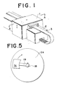
- the reference numeral 1 denotes a work pallet provided slidably on a base 2.
- the work pallet 1 is formed to be gate-shaped, to be fitted to the base 2 from above so as not to be swayed sidewise and to be slid with a timing belt 3.
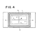
- a recess 4 is provided on the periphery of the bottom surface of the above mentioned work pallet 1.
- a hollow flexible sealing member 5 closed at the lower end and having a habit of normally contracting to be flat is provided in said recess 4.
- Said flexible sealing member 5 is formed of rubber or plastics, is opened above and is fitted in the above mentioned recess 4.
- An air passing hole 6 provided from the work pallet 1 is connected with the opened part so as to be able to feed air into the flexible sealing member 5 through the air passing hole 6.
- a groove 7 is evenly formed on the lower surface of the work pallet 1 except the above mentioned recess 4 as shown in Fig. 4.
- An air passing hole 8 provided separately from the above mentioned air passing hole 6 in the work pallet 1 is connected with said groove 7.
- 8a is an orifice for adjusting the amount of air feed.
- the work pallet 1 of the above mentioned formation is used, for example, as shown in Figs. 2 and 3.
- 9 is an ejector pump jetting compressed air through a compressed air feeding nozzle 9a to keep an internal partition chamber 9b under a negative pressure.
- 10 is a compressed air feeding source or concretely a compressor.
- 11 is a switching valve to be switched to the compressed air feeding source 10, ejector pump 9 and work pallet 1.
- 12 is a piping to the switching valve 11 from the compressed air feeding source 10.
- 13 is a piping to the ejector pump 9 from the switching valve 11.
- 14 is a piping to the air passing hole 6 of the work pallet 1 from the switching valve 11.
- 15 is a piping to the air passing hole 8 of the work pallet 1 from the switching valve 11.
- 16 is a piping to the switching valve 11 from the air passing hole 8 of the work pallet 1.
- 17 is a piping connecting the switching valve 11 and the partition chamber 9b of the ejector pump 9 with each other.
- the flexible sealing member 5 will remain contracted to be flat so as not to prevent the work pallet 1 from sliding.
- the work pallet 1 may be slid by using the timing belt 3 as shown in Fig. 1 or by utilizing a ball screw and screw, a rack and pinion or a linear motor.
- sucking contact is different from that of the conventional sucker made of a flexible member, the sucking contact area is larger and the metal surfaces are sucked into contact with each other so as not to be deviated from each other at all and not to be moved by any external force.
- FIG. 5 Another embodiment is shown in Fig. 5. That is to say, a table 2a is provided instead of the base and a work pallet 1a is rotated on said table 2a.
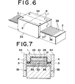
- Fig. 6 is a general perspective view of this embodiment.
- 1 is a work pallet and 2 is a base movably supporting the work pallet 1.
- the work pallet 1 is formed of a plurality of iron cores 22, 23 and 24 set through a nonmagnetic member 21 within a recess 20 on the lower surface of the work pallet 1, two-phase coils 25 and 26, nonmagnetic members 27, 28 and 29 covering respectively the lower surfaces of the iron cores 22, 23 and 24, air feeding holes 30 delivering compressed air and opening on the lower surface of the work pallet 1 including these nonmagnetic members 27, 28 and 29, grooves 31, an air sucking hole 32 introducing a vacuum pressure and a hollow flexible sealing member 5 provided in the recess 4 on the peripheral edge of the lower surface of the work pallet 1 and extending and contracting with the feed and discharge of compressed air from the air feeding hole 33.
- the above mentioned iron cores 22, 23 and 24 are arranged in series in the advancing direction of the work pallet 1 so as to contact with one another.
- the groove 31 is connected to the air feeding hole 30 and is formed to be lattice-shaped so as to enclose the air feeding hole 30.
- the above mentioned air sucking hole 32 is positioned intermediately between the two,air feeding grooves 31.
- the above mentioned flexible sealing member 5 is shaped to be endless and encloses all of the above mentioned grooves 31, air feeding holes 30 and air sucking hole 32 on the lower surface of the work pallet 1 from outside.
- each guide plate 34 is a guide plate fixed on each side of the work pallet 1.
- the inside surfaces of the guide plates 34 are opposed to both sides of the base 2.
- An air feeding hole 35 for feeding compressed air to form an air film between the inside surface of the guide plate 34 and the outside surface of the base 2 is provided on the inside surface of each guide plate 34.
- the above mentioned base 2 is formed of a conductor.
- a plurality of serrated projections 37 and recesses 36 are parallelly provided in the lengthwise direction on the surface of this conductor as illustrated.
- the projection 37 forms a short-circuiting conductor as an inductor for a linear motor so that electricity may be short-circuited at both ends of the projection 37.
- the magnetic poles of the projections 37, iron cores 22, 23 and 24 and coils 25 and 26 form an induction type linear motor.
- 38 is a nonmagnetic member embedded in the recess 36.
- Fig. 10 shows still another embodiment wherein side recesses 39 are provided respectively in two guide plates 34A holding the bases 2 and a plurality of iron cores 41 on which the same coils as are shown in Fig. 9 are fitted through a nonmagnetic member 40 in each recess 39. Projections and recesses are provided also on the base sides opposed to the end surfaces of the iron cores 41. The projections are short-circuiting conductors and these projections and the iron cores 41 having the above mentioned coils wound on them form respectively the same induction type linear motors.
- the same endless sealing members 5A as are already described are fitted respectively to the peripheries of the surfaces opposed to the base 2 of the guide plates 34A so that compressed air can be fed to the sealing members 5A simultaneously with the above mentioned sealing member 5.
- vacuum pressure introducing air sucking holes acting the same as are described above are present on the sides of the guide plates 34A enclosed with the respective sealing members 5A.
- three sets of linear motors and air sliding devices in the upper part and both side parts are combined to obtain a sufficiently high torque propelling force and position holding force and to be effective to convey heavy works.
Landscapes
- Engineering & Computer Science (AREA)
- Mechanical Engineering (AREA)
- General Engineering & Computer Science (AREA)
- Physics & Mathematics (AREA)
- Fluid Mechanics (AREA)
- Feeding Of Workpieces (AREA)
Applications Claiming Priority (4)
| Application Number | Priority Date | Filing Date | Title |
|---|---|---|---|
| JP11661983A JPS609621A (ja) | 1983-06-28 | 1983-06-28 | エア−スライド及び静止用支持台 |
| JP116619/83 | 1983-06-28 | ||
| JP18224983A JPS6076943A (ja) | 1983-09-30 | 1983-09-30 | 送り装置 |
| JP182249/83 | 1983-09-30 |
Publications (2)
| Publication Number | Publication Date |
|---|---|
| EP0130905A1 true EP0130905A1 (fr) | 1985-01-09 |
| EP0130905B1 EP0130905B1 (fr) | 1987-07-29 |
Family
ID=26454918
Family Applications (1)
| Application Number | Title | Priority Date | Filing Date |
|---|---|---|---|
| EP84401355A Expired EP0130905B1 (fr) | 1983-06-28 | 1984-06-26 | Dispositif de glissement à coussin d'air pour palettes de travail ou similaires |
Country Status (3)
| Country | Link |
|---|---|
| US (1) | US4627362A (fr) |
| EP (1) | EP0130905B1 (fr) |
| DE (1) | DE3465063D1 (fr) |
Cited By (9)
| Publication number | Priority date | Publication date | Assignee | Title |
|---|---|---|---|---|
| FR2583670A1 (fr) * | 1985-06-21 | 1986-12-26 | Teramachi Hiroshi | Dispositif d'avance de table |
| DE3725854A1 (de) * | 1986-08-06 | 1988-03-17 | Dea Spa | Luftkissen-lagerschuh |
| FR2639704A1 (fr) * | 1988-11-30 | 1990-06-01 | Micro Controle | Mecanisme a mouvements croises |
| FR2650526A1 (fr) * | 1989-08-03 | 1991-02-08 | Jeanniard Christian | Appareil pour fabriquer des structures par exemple en bois, telles que des fermes pour charpentes, utilisant plusieurs socles munis d'un dispositif de maintien pneumatique a depression, permettant de les maintenir en place fermement |
| EP0294731A3 (fr) * | 1987-06-06 | 1991-07-03 | Johann A. Krause Maschinenfabrik GmbH | Ligne de fabrication et procédé de fabrication de pièces sur celle-ci |
| WO1992004979A1 (fr) * | 1990-09-13 | 1992-04-02 | MAX-PLANCK-Gesellschaft zur Förderung der Wissenschaften e.V. | Procede et dispositif d'ajustement de la temperature de substances chimiques, biochimiques et/ou microbiologiques |
| EP0701881A1 (fr) * | 1994-09-11 | 1996-03-20 | A RÖMHELD GmbH & CO KG | Système d'usinage |
| WO2011089222A1 (fr) * | 2010-01-21 | 2011-07-28 | Carl Zeiss Industrielle Messtechnik Gmbh | Machine munie d'un palier à air et procédé permettant de faire fonctionner une telle machine |
| WO2018228715A1 (fr) * | 2017-06-14 | 2018-12-20 | Hochschule Niederrhein | Dispositif palier lisse hydrostatique |
Families Citing this family (16)
| Publication number | Priority date | Publication date | Assignee | Title |
|---|---|---|---|---|
| US5077523A (en) * | 1989-11-03 | 1991-12-31 | John H. Blanz Company, Inc. | Cryogenic probe station having movable chuck accomodating variable thickness probe cards |
| US5160883A (en) * | 1989-11-03 | 1992-11-03 | John H. Blanz Company, Inc. | Test station having vibrationally stabilized X, Y and Z movable integrated circuit receiving support |
| US5166606A (en) * | 1989-11-03 | 1992-11-24 | John H. Blanz Company, Inc. | High efficiency cryogenic test station |
| JP2864155B2 (ja) * | 1990-07-12 | 1999-03-03 | キタムラ機械株式会社 | パレット交換装置 |
| JP3128709B2 (ja) * | 1992-08-04 | 2001-01-29 | 株式会社新川 | 非接触型移動テーブル |
| US5715585A (en) * | 1994-09-11 | 1998-02-10 | A. Roemheld Gmbh & Co. Kg | Work piece machining system |
| US5848930A (en) * | 1995-09-13 | 1998-12-15 | The Boeing Company | Aircraft trimming device |
| DE10117632A1 (de) * | 2001-04-09 | 2002-10-17 | Awu Praez Swellen Gmbh & Co Kg | Vorrichtung mit einer luftgleitgelagerten, translatorisch bewegbaren Plattform |
| US7134668B2 (en) * | 2001-10-24 | 2006-11-14 | Ebara Corporation | Differential pumping seal apparatus |
| TWI222423B (en) * | 2001-12-27 | 2004-10-21 | Orbotech Ltd | System and methods for conveying and transporting levitated articles |
| US20060127252A1 (en) * | 2004-12-13 | 2006-06-15 | Hamilton Sundstrand Corporation | Reciprocating pump system |
| WO2006115157A1 (fr) * | 2005-04-22 | 2006-11-02 | Rorze Corporation | Système de convoyage de cassette |
| US8453337B2 (en) * | 2009-06-02 | 2013-06-04 | James Richard Lacy | System and method for workpiece coordinate measurements |
| ES2753536T3 (es) | 2011-02-21 | 2020-04-13 | Novus Finitor B V | Sistema de levitación para un tren |
| CN105946872A (zh) * | 2016-06-08 | 2016-09-21 | 忻琦 | 一种双步进电机驱动橡胶履带夹紧式单轨行走系统 |
| FR3139869A1 (fr) * | 2022-09-16 | 2024-03-22 | Micro-Contrôle - Spectra-Physics | Appareil pour la réduction des vibrations dans un système de régulation de mouvement à coussin d’air |
Citations (2)
| Publication number | Priority date | Publication date | Assignee | Title |
|---|---|---|---|---|
| US3493070A (en) * | 1965-04-30 | 1970-02-03 | Bertin & Cie | Gas-cushion devices intended to support or guide a movable load |
| DD127220A1 (de) * | 1976-09-03 | 1977-09-14 | Fritz Kutzscher | Vorrichtung zum erzeugen eines luftkissens zum bewegen hoher, schlanker lasten |
Family Cites Families (12)
| Publication number | Priority date | Publication date | Assignee | Title |
|---|---|---|---|---|
| US3246608A (en) * | 1964-01-13 | 1966-04-19 | Richard C Cooper | Conveyor system |
| FR1393365A (fr) * | 1964-01-21 | 1965-03-26 | Bertin & Cie | Perfectionnements aux joints d'étanchéité applicables aux véhicules à coussin d'air associés à une voie |
| GB1203025A (en) * | 1966-09-06 | 1970-08-26 | Hovercraft Dev Ltd | Electromagnetically-propelled gas cushion vehicle |
| US3610365A (en) * | 1970-06-17 | 1971-10-05 | Nasa | Air bearing |
| US3644762A (en) * | 1971-02-22 | 1972-02-22 | Tracked Hovercraft Ltd | Linear induction motor stator |
| US3757699A (en) * | 1971-04-15 | 1973-09-11 | Uniflo Systems Co | Pneumatic suspension system |
| US3820467A (en) * | 1972-10-18 | 1974-06-28 | Rolair Syst Inc | Conveyor system with air in floor |
| US3827364A (en) * | 1972-10-25 | 1974-08-06 | Rohr Industries Inc | Adhesion air bearing feedback control apparatus and method |
| US3855901A (en) * | 1973-10-15 | 1974-12-24 | Babcock & Wilcox Co | Broaching machine |
| US4165132A (en) * | 1977-02-28 | 1979-08-21 | International Business Machines Corporation | Pneumatic control of the motion of objects suspended on an air film |
| US4470578A (en) * | 1979-03-30 | 1984-09-11 | Idux Industriell Exploatering Aktiebolag | Load transfer device |
| US4441571A (en) * | 1981-02-02 | 1984-04-10 | Wood Kenneth G | Fluid bearing |
-
1984
- 1984-06-20 US US06/622,730 patent/US4627362A/en not_active Expired - Fee Related
- 1984-06-26 DE DE8484401355T patent/DE3465063D1/de not_active Expired
- 1984-06-26 EP EP84401355A patent/EP0130905B1/fr not_active Expired
Patent Citations (2)
| Publication number | Priority date | Publication date | Assignee | Title |
|---|---|---|---|---|
| US3493070A (en) * | 1965-04-30 | 1970-02-03 | Bertin & Cie | Gas-cushion devices intended to support or guide a movable load |
| DD127220A1 (de) * | 1976-09-03 | 1977-09-14 | Fritz Kutzscher | Vorrichtung zum erzeugen eines luftkissens zum bewegen hoher, schlanker lasten |
Cited By (12)
| Publication number | Priority date | Publication date | Assignee | Title |
|---|---|---|---|---|
| FR2583670A1 (fr) * | 1985-06-21 | 1986-12-26 | Teramachi Hiroshi | Dispositif d'avance de table |
| DE3725854A1 (de) * | 1986-08-06 | 1988-03-17 | Dea Spa | Luftkissen-lagerschuh |
| EP0294731A3 (fr) * | 1987-06-06 | 1991-07-03 | Johann A. Krause Maschinenfabrik GmbH | Ligne de fabrication et procédé de fabrication de pièces sur celle-ci |
| FR2639704A1 (fr) * | 1988-11-30 | 1990-06-01 | Micro Controle | Mecanisme a mouvements croises |
| FR2650526A1 (fr) * | 1989-08-03 | 1991-02-08 | Jeanniard Christian | Appareil pour fabriquer des structures par exemple en bois, telles que des fermes pour charpentes, utilisant plusieurs socles munis d'un dispositif de maintien pneumatique a depression, permettant de les maintenir en place fermement |
| WO1992004979A1 (fr) * | 1990-09-13 | 1992-04-02 | MAX-PLANCK-Gesellschaft zur Förderung der Wissenschaften e.V. | Procede et dispositif d'ajustement de la temperature de substances chimiques, biochimiques et/ou microbiologiques |
| US5430957A (en) * | 1990-09-13 | 1995-07-11 | Max-Planck-Gesellschaft Zur Forderung Der Wissenschaften E.V. | Installation and process for the temperature control of chemical and/or biochemical and/or microbiological substances |
| EP0701881A1 (fr) * | 1994-09-11 | 1996-03-20 | A RÖMHELD GmbH & CO KG | Système d'usinage |
| WO2011089222A1 (fr) * | 2010-01-21 | 2011-07-28 | Carl Zeiss Industrielle Messtechnik Gmbh | Machine munie d'un palier à air et procédé permettant de faire fonctionner une telle machine |
| US8590875B2 (en) | 2010-01-21 | 2013-11-26 | Carl Zeiss Industrielle Messtechnik Gmbh | Machine having an air bearing and method for operating such a machine |
| WO2018228715A1 (fr) * | 2017-06-14 | 2018-12-20 | Hochschule Niederrhein | Dispositif palier lisse hydrostatique |
| CN111033069A (zh) * | 2017-06-14 | 2020-04-17 | 下莱茵应用技术大学 | 静压滑动轴承组件 |
Also Published As
| Publication number | Publication date |
|---|---|
| DE3465063D1 (en) | 1987-09-03 |
| EP0130905B1 (fr) | 1987-07-29 |
| US4627362A (en) | 1986-12-09 |
Similar Documents
| Publication | Publication Date | Title |
|---|---|---|
| EP0130905B1 (fr) | Dispositif de glissement à coussin d'air pour palettes de travail ou similaires | |
| EP1240974A3 (fr) | Machine-outil avec au moins deux unités d'usinage | |
| JP2017105520A (ja) | キャリアテープ走行装置 | |
| FR2464125B1 (fr) | ||
| EP0145507A1 (fr) | Appareil pour déplacer et arrêter des outils | |
| EP4397604A1 (fr) | Convoyeur à mouvement alternatif | |
| CN211540590U (zh) | 一种连续自动磨削机 | |
| CN218426719U (zh) | 一种磁吸件装配磁体的全自动组装设备 | |
| CN112658683A (zh) | 一种转盘式两平面自动钻攻机 | |
| KR200470580Y1 (ko) | 핀 타설 장치 | |
| US6568558B2 (en) | Electronic component feeding apparatus | |
| JP2663584B2 (ja) | 作業機構の直線搬送装置 | |
| CN120715593A (zh) | 一种铁件上料组件及其应用的海尔贝克磁组件的组装设备 | |
| US4739143A (en) | Discharge machining apparatus with wire electrode reversal | |
| US5816385A (en) | Magnetic conveying device with non-magnetic guide rails | |
| US5988430A (en) | Part supply apparatus | |
| CN217534621U (zh) | 一种磁钢自动充磁检测设备 | |
| CN219684983U (zh) | 一种圆盘镜面通过式磨床 | |
| CN215847062U (zh) | 一种具有定位导引结构的精密加工治具 | |
| CN111687231A (zh) | 一种铝型材成型用多工序换位式加工组合机 | |
| CN210878045U (zh) | 一种零配件焊接装置 | |
| JP3361984B2 (ja) | リニアモータ駆動装置の保護装置 | |
| CN117021501B (zh) | 一种自动切水口下料装置 | |
| CN213568406U (zh) | 一种芯片取放机构 | |
| CN220596254U (zh) | 下料装置 |
Legal Events
| Date | Code | Title | Description |
|---|---|---|---|
| PUAI | Public reference made under article 153(3) epc to a published international application that has entered the european phase |
Free format text: ORIGINAL CODE: 0009012 |
|
| AK | Designated contracting states |
Designated state(s): CH DE FR GB LI |
|
| 17P | Request for examination filed |
Effective date: 19850425 |
|
| GRAA | (expected) grant |
Free format text: ORIGINAL CODE: 0009210 |
|
| AK | Designated contracting states |
Kind code of ref document: B1 Designated state(s): CH DE FR GB LI |
|
| REF | Corresponds to: |
Ref document number: 3465063 Country of ref document: DE Date of ref document: 19870903 |
|
| ET | Fr: translation filed | ||
| PLBE | No opposition filed within time limit |
Free format text: ORIGINAL CODE: 0009261 |
|
| STAA | Information on the status of an ep patent application or granted ep patent |
Free format text: STATUS: NO OPPOSITION FILED WITHIN TIME LIMIT |
|
| 26N | No opposition filed | ||
| GBPC | Gb: european patent ceased through non-payment of renewal fee | ||
| REG | Reference to a national code |
Ref country code: GB Ref legal event code: 728C |
|
| PGFP | Annual fee paid to national office [announced via postgrant information from national office to epo] |
Ref country code: FR Payment date: 19920629 Year of fee payment: 9 |
|
| PGFP | Annual fee paid to national office [announced via postgrant information from national office to epo] |
Ref country code: CH Payment date: 19920701 Year of fee payment: 9 |
|
| PGFP | Annual fee paid to national office [announced via postgrant information from national office to epo] |
Ref country code: GB Payment date: 19920803 Year of fee payment: 9 |
|
| REG | Reference to a national code |
Ref country code: GB Ref legal event code: 728A |
|
| PG25 | Lapsed in a contracting state [announced via postgrant information from national office to epo] |
Ref country code: GB Effective date: 19930626 |
|
| PG25 | Lapsed in a contracting state [announced via postgrant information from national office to epo] |
Ref country code: LI Effective date: 19930630 Ref country code: CH Effective date: 19930630 |
|
| GBPC | Gb: european patent ceased through non-payment of renewal fee |
Effective date: 19930626 |
|
| PG25 | Lapsed in a contracting state [announced via postgrant information from national office to epo] |
Ref country code: FR Effective date: 19940228 |
|
| REG | Reference to a national code |
Ref country code: CH Ref legal event code: PL |
|
| REG | Reference to a national code |
Ref country code: FR Ref legal event code: ST |
|
| PGFP | Annual fee paid to national office [announced via postgrant information from national office to epo] |
Ref country code: DE Payment date: 19950706 Year of fee payment: 12 |
|
| PG25 | Lapsed in a contracting state [announced via postgrant information from national office to epo] |
Ref country code: DE Effective date: 19970301 |