EP0130909B1 - Dispositif et procédé de refroidissement de feuilles plastiques - Google Patents
Dispositif et procédé de refroidissement de feuilles plastiques Download PDFInfo
- Publication number
- EP0130909B1 EP0130909B1 EP84401374A EP84401374A EP0130909B1 EP 0130909 B1 EP0130909 B1 EP 0130909B1 EP 84401374 A EP84401374 A EP 84401374A EP 84401374 A EP84401374 A EP 84401374A EP 0130909 B1 EP0130909 B1 EP 0130909B1
- Authority
- EP
- European Patent Office
- Prior art keywords
- bubble
- cooling device
- air
- cooling
- blowing
- Prior art date
- Legal status (The legal status is an assumption and is not a legal conclusion. Google has not performed a legal analysis and makes no representation as to the accuracy of the status listed.)
- Expired
Links
- 238000001816 cooling Methods 0.000 title claims description 39
- 238000000034 method Methods 0.000 title claims description 13
- 239000002985 plastic film Substances 0.000 title claims description 5
- 229920006255 plastic film Polymers 0.000 title claims 3
- 238000007664 blowing Methods 0.000 claims description 29
- 239000000463 material Substances 0.000 claims description 22
- -1 polyethylenes Polymers 0.000 claims description 11
- 239000004698 Polyethylene Substances 0.000 claims description 9
- 229920000573 polyethylene Polymers 0.000 claims description 9
- 230000008569 process Effects 0.000 claims description 8
- 239000000155 melt Substances 0.000 claims description 7
- 229920003023 plastic Polymers 0.000 claims description 7
- 239000004033 plastic Substances 0.000 claims description 7
- 239000011347 resin Substances 0.000 claims description 7
- 229920005989 resin Polymers 0.000 claims description 7
- 238000004519 manufacturing process Methods 0.000 claims description 6
- 239000000203 mixture Substances 0.000 claims description 3
- 239000004743 Polypropylene Substances 0.000 claims description 2
- 229920001155 polypropylene Polymers 0.000 claims description 2
- VXNZUUAINFGPBY-UHFFFAOYSA-N 1-Butene Chemical compound CCC=C VXNZUUAINFGPBY-UHFFFAOYSA-N 0.000 claims 1
- 150000003254 radicals Chemical class 0.000 description 8
- 230000000052 comparative effect Effects 0.000 description 7
- 230000003287 optical effect Effects 0.000 description 7
- 238000010101 extrusion blow moulding Methods 0.000 description 5
- 230000004907 flux Effects 0.000 description 4
- 230000004048 modification Effects 0.000 description 4
- 238000012986 modification Methods 0.000 description 4
- 229920000092 linear low density polyethylene Polymers 0.000 description 3
- 239000004707 linear low-density polyethylene Substances 0.000 description 3
- 229920001684 low density polyethylene Polymers 0.000 description 3
- 239000004702 low-density polyethylene Substances 0.000 description 3
- 230000007547 defect Effects 0.000 description 2
- 238000007711 solidification Methods 0.000 description 2
- 230000008023 solidification Effects 0.000 description 2
- 239000005977 Ethylene Substances 0.000 description 1
- 230000009471 action Effects 0.000 description 1
- 238000000137 annealing Methods 0.000 description 1
- 230000008859 change Effects 0.000 description 1
- 229920001577 copolymer Polymers 0.000 description 1
- 230000000694 effects Effects 0.000 description 1
- 238000001125 extrusion Methods 0.000 description 1
- 229920001903 high density polyethylene Polymers 0.000 description 1
- 239000004700 high-density polyethylene Substances 0.000 description 1
- 238000005259 measurement Methods 0.000 description 1
- 239000012768 molten material Substances 0.000 description 1
- 238000000465 moulding Methods 0.000 description 1
- 229920001748 polybutylene Polymers 0.000 description 1
Images


Classifications
-
- B—PERFORMING OPERATIONS; TRANSPORTING
- B29—WORKING OF PLASTICS; WORKING OF SUBSTANCES IN A PLASTIC STATE IN GENERAL
- B29C—SHAPING OR JOINING OF PLASTICS; SHAPING OF MATERIAL IN A PLASTIC STATE, NOT OTHERWISE PROVIDED FOR; AFTER-TREATMENT OF THE SHAPED PRODUCTS, e.g. REPAIRING
- B29C48/00—Extrusion moulding, i.e. expressing the moulding material through a die or nozzle which imparts the desired form; Apparatus therefor
- B29C48/25—Component parts, details or accessories; Auxiliary operations
- B29C48/88—Thermal treatment of the stream of extruded material, e.g. cooling
- B29C48/885—External treatment, e.g. by using air rings for cooling tubular films
-
- B—PERFORMING OPERATIONS; TRANSPORTING
- B29—WORKING OF PLASTICS; WORKING OF SUBSTANCES IN A PLASTIC STATE IN GENERAL
- B29C—SHAPING OR JOINING OF PLASTICS; SHAPING OF MATERIAL IN A PLASTIC STATE, NOT OTHERWISE PROVIDED FOR; AFTER-TREATMENT OF THE SHAPED PRODUCTS, e.g. REPAIRING
- B29C48/00—Extrusion moulding, i.e. expressing the moulding material through a die or nozzle which imparts the desired form; Apparatus therefor
- B29C48/03—Extrusion moulding, i.e. expressing the moulding material through a die or nozzle which imparts the desired form; Apparatus therefor characterised by the shape of the extruded material at extrusion
- B29C48/09—Articles with cross-sections having partially or fully enclosed cavities, e.g. pipes or channels
- B29C48/10—Articles with cross-sections having partially or fully enclosed cavities, e.g. pipes or channels flexible, e.g. blown foils
-
- B—PERFORMING OPERATIONS; TRANSPORTING
- B29—WORKING OF PLASTICS; WORKING OF SUBSTANCES IN A PLASTIC STATE IN GENERAL
- B29C—SHAPING OR JOINING OF PLASTICS; SHAPING OF MATERIAL IN A PLASTIC STATE, NOT OTHERWISE PROVIDED FOR; AFTER-TREATMENT OF THE SHAPED PRODUCTS, e.g. REPAIRING
- B29C48/00—Extrusion moulding, i.e. expressing the moulding material through a die or nozzle which imparts the desired form; Apparatus therefor
- B29C48/25—Component parts, details or accessories; Auxiliary operations
- B29C48/88—Thermal treatment of the stream of extruded material, e.g. cooling
- B29C48/911—Cooling
- B29C48/9115—Cooling of hollow articles
- B29C48/912—Cooling of hollow articles of tubular films
Definitions
- the present invention relates to a cooling device and a method for manufacturing plastic sheets obtained by blowing sheaths.
- Such a device has already been described in the European patent application published under the number 0 041 803. This device makes it possible to extrude polyethylene sheets at an inflation rate equal to 2. However, it has the disadvantage of not allowing a satisfactory extrusion of polyethylene sheets at an inflation rate greater than 2, as demonstrated in the comparative examples below. On the other hand, such a device has the drawback of being able to improve the optical properties of the sheath only for resins, such as radical low density polyethylene, ethylene / vinyl acetate copolymer and linear low density polyethylene, the properties of which optics were already relatively satisfactory.
- resins such as radical low density polyethylene, ethylene / vinyl acetate copolymer and linear low density polyethylene
- the present invention aims to allow more efficient cooling when the need arises and therefore to obtain blown sheaths with good optical properties, in particular clarity, cloudiness, at a high flow rate and for a large number of resins.
- the device according to the invention disposed above an annular die, comprises at its lower part a lower chamber (3, 4), at its intermediate part an intensive blowing ring (10) whose air jet ( 9) is directed towards the sheath (1), this ring having the function of accelerating the solidification of the material, at its upper part an upper chamber (14, 15) in which the sheath is in contact with the air flow (7) directed in the direction of draw of the sheath and it is characterized in that the lower chamber (3, 4) is provided with at least one opening (6) allowing the intake of aspirated air (8) by the air flow (7).
- Each opening (6) of said lower chamber (3,4) can be adjustable by means of a system consisting for example of discs with holes.
- said lower chamber can have an adjustable height, advantageously obtained by a series of nestable elements of different heights.
- the upper chamber can have an adjustable height advantageously obtained by a series of nestable elements of different height.
- the device may further comprise means making it possible to modify the flow rate of the directed air flow, at the level of the upper chamber, in the direction of drawing of the sheath.
- the intensive blowing ring is advantageously formed so that the angle A defined between the axis perpendicular to the sheath and the direction of the air jet leaving the ring is between 0 and 85 °.
- the device can further comprise an internal cooling system comprising at least one air supply channel and at least one forced air evacuation channel axially passing through the annular die.
- the cooling system may include an axial inlet channel for the annular die, at the center of which is an air outlet channel, for the purpose of cooling the internal part of the sheath.
- This internal cooling system can also be adjustable in height by means of at least one interlocking element.
- This interlocking element may comprise at least one sealed part and / or at least one part having openings in order to allow an air flow to escape, the latter having the function of cooling the interior of the sheath, from the outlet of the sector and, even before. that it is in contact with the air flows leaving the internal cooling system proper.
- the intensity of the air flow coming from the intensive blowing ring can be modified by changing the thickness F of the blowing lip of this ring between 0.1 mm and 15 mm; the term “blowing lip” is understood to mean the edges of the opening allowing the passage of the jet of air leaving the intensive blowing ring towards the sheath.
- the sheath of material 1 is obtained from molten material coming from the annular die 2, by following the path of the material from the die, the sheath is of first moderately cooled in the lower chamber consisting of at least two interlocking elements 3 and 4, this chamber comprises at its lower part a system of adjustable openings 5 making it possible to adjust the intake of aspirated air 6 under the effect of depression generated by the air flow 7 projected into the upper chamber formed by the elements 14 and 15; in this first part, the sheath is moderately cooled by the air flow 8 and does not undergo significant dimensional changes. The sheath is then violently cooled by means of an air jet 9 exiting from the blowing ring 10, the direction of this jet being perpendicular to said sheath 1.
- the sheath After having left the blowing ring 10, the sheath arrives in bedroom upper consisting of at least 2 nestable elements 14 and 15, in which there is an air flow allowing the air to exit according to the flows 7 in the upper chamber constituted by the elements 14 and 15 in the direction of draft the sheath 1, the air flow rate 7 being modifiable by means of the adjustment system 12. It is in this upper chamber that the sheath takes its final dimension under the action of the air overpressure which prevails at inside of it, the overpressure air being introduced through the pressurizing tube 16. Finally, the sheath is definitively solidified and pulled by means of the drive system 17.
- the air flow disturbances 7 are reduced by placing, for example, a grid with holes 18, disposed on the air outlet adjustment system 12.
- the overpressure air is introduced into the upper chamber by a cooling system 19 , placed inside said sheath 1, adjustable in height by means of nestable elements 20, 21 and 22, element 22 being provided with openings in order to allow an air flow to escape from the outlet of the sector.
- This cooling system comprises an air intake channel 19Aa and an air evacuation channel 19B.
- sheath is definitively solidified and pulled by means of a drive system 17 (not shown) of the same type as that shown previously for the first embodiment.
- a second object of the invention consists in a process for manufacturing plastic sheets by blowing sheath, comprising on the one hand an extrusion-blowing step of molten plastic material coming from an extruder die and on the other hand a step of cooling the blown sheath thus obtained, characterized in that the cooling step is carried out by passing the sheath through a device of the type previously described.
- the ratio of the air flow rate drawn into the lower chamber to the air flow rate introduced into the blowing ring to be between 0.1 and 0.5.
- the process according to the invention has the advantages of obtaining films with good properties (clarity, cloudiness) from resins such as radical polyethylene, high density polyethylene, polypropylene, polybutene-1, linear low density polyethylene and their mixtures, having a fluidity index (determined according to standard ASTM D 1238/73) of between 0.1 and 10 dg / min.
- resins such as radical polyethylene, high density polyethylene, polypropylene, polybutene-1, linear low density polyethylene and their mixtures, having a fluidity index (determined according to standard ASTM D 1238/73) of between 0.1 and 10 dg / min.
- the method according to the invention makes it possible to manufacture films having good optical properties from radical polyethylene with a melt index greater than 3 dg / min, while this resin has hitherto been reserved for the manufacture of objects by molding techniques.
- this process also makes it possible to obtain films at rates or / and inflation rates which are significantly higher than those authorized by the process of European patent application No. 0 041 803.
- the ratio R of the air flow drawn into the lower chamber to the air flow introduced into the blowing ring is shown in Table 1 below.
- the inflation rate TG ratio of the diameter of the sheath to that of the die
- the material flow rate Q expressed in kg / hour
- the material used is a free radical low density polyethylene sold under the brand LOTRENE FA 0401 (manufactured by CdF Chimie) having a melt index of 4 dg / min (measured according to ASTM D 1238-73) and a density of 0.918.
- Films 40 microns thick are produced by extrusion blow molding of the same material as that used in Examples 1 to 4 above and on the same extruder as that of said examples, then cooling by means of a device of the type described in European patent application No. 0 041 803.
- Table II below are reported on the one hand the operating conditions such as Q, TG and R, and on the other hand the results of the properties obtained on the blown sheath.
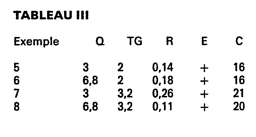
- the material used is free radical low density polyethylene marketed under the brand LOTRENE FB 5026 (manufactured by CdF Chimie) having a melt index of 0.6 dg / min (measured according to ASTM D 1238-73) and a density of 0.921 .
- Table III below are reported the operating conditions such as Q, TG and R as well as the results obtained on the blown sheath 40 micrometers thick, this by means of the same device as that of Examples 1 to 4.
- Blown sheath 40 micrometers thick by extrusion blow molding, is produced from the same plastic material as that used in Examples 5 to 8, and by means of the same device as that used in Examples 1A to 4A.
- the operating conditions as well as the results obtained are reproduced in Table IV below; in which the extrudability noted (0) indicates that it is impossible to obtain blown sheath.
- Example 9 the cooling system is the device described in FIG. 1; in Example 9A, it is of the type described in European patent application No. 0 041 803. T represents the haze expressed in% and determined according to standard ASTM D 103-77. The extruder used is the same as that of Examples 1 to 8.
- Films are produced by extrusion blow molding of plastic material from the die of an industrial extruder marketed by the company WINDMOLLER & HOLSCHER with a screw diameter of 60 mm, then cooling by the device described above and represented in FIG. 2 .
- the material used is low-density radical polyethylene marketed under the brand LOTRENE FB 3010 by the company CdF CHIMIE having a melt index of 0.25 dg / min (measured according to ASTM D 1238-73) and a density of 0.922.
- Films are made by means of the same extruder and from the same material as those used in Examples 10 to 12, but this time taking, to cool the sheath, a device of the same type as that used in the examples 10 to 12 above but for which the openings located at the bottom of the lower chamber were closed in order to make it closed.
- the material flow is also 108 kg / h.
- the operating conditions as well as the results obtained are reproduced in Table VII below.
- the same device is used as that used for tests 10 to 12.
- the plastic material used is low density radical polyethylene sold under the brand LOTRENE FB 5005 by the company CdF CHIMIE having a melt index of 0.6 dg / min ( measured according to standard ASTM D 1236-73) and a density of 0.921.
- Blown sheath is made from the same material as that used for tests 13 to 15 but this time using the device already used in Comparative Examples 10A to 12A.
- the flow rate is identical to that of Examples 13 to 15, that is to say 102 kg / h.
- Films are produced by extrusion blow molding from a mixture of resins consisting, in addition, of 75% of linear polyethylene marketed under the brand LOTREX FW 1290 by the company CdF CHIMIE and of 25% of radical polyethylene marketed under the brand LOTRENE FB 3010 by the company CdF CHIMIE.
- the device used is that already used in examples 10 to 15; and in example 16A the device used is that already used in examples 10A to 15A.
Landscapes
- Engineering & Computer Science (AREA)
- Mechanical Engineering (AREA)
- Physics & Mathematics (AREA)
- Thermal Sciences (AREA)
- Extrusion Moulding Of Plastics Or The Like (AREA)
- Shaping By String And By Release Of Stress In Plastics And The Like (AREA)
- Laminated Bodies (AREA)
- Heating, Cooling, Or Curing Plastics Or The Like In General (AREA)
Description
- La présente invention concerne un dispositif de refroidissement et un procédé de fabrication de feuilles plastiques obtenues par soufflage de gaine.
- On connait déjà un dispositif destiné à obtenir de la feuille en gaine soufflée de bonne clarté, constitué par un ensemble de trois éléments juxtaposés; celui-ci se compose, en suivant le trajet de la gaine, à sa partie basse, d'une chambre close dite de recuit, puis à sa partie intermédiaire, d'un anneau de soufflage intensif dont le flux d'air est dirigé perpendiculairement à la gaine, cet anneau ayant pour fonction d'accélérer la solidification de la matière, et enfin à sa partie haute d'une chambre supérieure dans laquelle la gaine est en contact avec un flux d'air dirigé dans la direction de tirage de la gaine.
- Un tel dispositif a déjà été décrit dans la demande de brevet européen publié sous le numéro 0 041 803. Ce dispositif permet d'extruder des feuilles de polyéthylène selon un taux de gonflage égal à 2. Cependant il présente l'inconvénient de ne pas permettre une extrusion satisfaisante de feuilles de polyéthylène selon un taux de gonflage supérieur à 2, comme on le démontre dans les exemples comparatifs ci-après. D'autre part un tel dispositif présente l'inconvénient de ne pouvoir améliorer les propriétés optiques de la gaine que pour des résines, telle que polyéthylène basse densité radicalaire, copolymère d'éthylène/acétate de vinyle et polyéthylène basse densité linéaire, dont les propriétés optiques étaient déjà relativement satisfaisantes. Par propriétés optiques satisfaisantes pour l'application à la fabrication de gaines, on entend un trouble (déterminé selon la norme ASTM D 103-77) non supérieur à 7 %. Enfin un dernier inconvénient de ce dispositif réside dans l'impossibilité d'améliorer les propriétés optiques de la gaine (par rapport à un système classique de refroidissement) tout en assurant un débit élevé de matière.
- La présente invention a pour but de permettre un refroidissement plus efficace quand la nécessité s'en fait sentir et donc d'obtenir des gaines soufflées de bonnes propriétés optiques, notamment clarté, trouble, à un débit important et pour un grand nombre de résines.
- Le dispositif selon l'invention, disposé au-dessus d'une filière annulaire, comprend à sa partie inférieure une chambre basse (3, 4), à sa partie intermédiaire un anneau de soufflage intensif (10) dont le jet d'air (9) est dirigé vers la gaine (1), cet anneau ayant pour fonction d'accélérer la solidification de la matière, à sa partie supérieure une chambre haute (14, 15) dans laquelle la gaine est en contact avec le flux d'air (7) dirigé dans la direction de tirage de la gaine et il se caractérise par le fait que la chambre basse (3, 4) est munie d'au moins une ouverture (6) permettant l'admission d'air aspiré (8) par le flux d'air (7).
- Chaque ouverture (6) de ladite chambre basse (3,4) peut être réglable au moyen d'un système constitué par exemple de disques à trous. En outre ladite chambre basse peut avoir une hauteur réglable, obtenue avantageusement par une série d'éléments emboîtables de hauteurs différentes. De la même manière la chambre haute peut avoir une hauteur réglable obtenue avantageusement par une série d'éléments emboîtables de hauteur différente. Le dispositif peut comporter, en outre, des moyens permettant de modifier le débit du flux d'air dirigé, au niveau de la chambre haute, dans la direction de tirage de la gaine.
- L'anneau de soufflage intensif est avantageusement constitué de telle sorte que l'angle A défini entre l'axe perpendiculaire à la gaine et la direction du jet d'air sortant de l'anneau, soit compris entre 0 et 85°.
- Selon un mode de réalisation de l'invention, le dispositif peut comprendre en outre un système de refroidissement interne comprenant au moins un canal d'amenée d'air et au moins un canal d'évacuation d'air pulsé traversant axialement la filière annulaire. Par exemple le système de refroidissement peut comprendre un canal d'arrivée axial de la filière annulaire, au centre duquel est disposé un canal de sortie d'air, en vue de refroidir la partie interne de la gaine.
- Ce système de refroidissement interne peut en outre être réglable en hauteur au moyen d'au moins un élément emboîtable. Cet élément emboîtable peut comporter au moins une partie étanche et/ou au moins une partie possédant des ouvertures en vue de laisser s'échapper un flux d'air, ce dernier ayant pour fonction de refroidir l'intérieur de la gaine, dès la sortie de la filière et, avant même. que celle-ci soit en contact des flux d'air sortant du système de refroidissement interne proprement dit.
- Selon un autre mode de réalisation de l'invention, l'intensité du flux d'air provenant de l'anneau de soufflage intensif peut être modifiée par changement de l'épaisseur F de la lèvre de soufflage de cet anneau entre 0,1 mm et 15 mm; on entend par lèvre de soufflage les bords de l'ouverture permettant le passage du jet d'air sortant de l'anneau de soufflage intensif vers la gaine.
- Dans le but de mieux faire comprendre l'invention, on va décrire maintenant à titre d'illustration et sans autre caractère limitatif deux modes de réalisation du dispositif, dont les figures 1 et 2, en annexe, représentent les vues en coupe. Les éléments numérotés 1 à 15 sur ces deux figures sont communs aux deux modes de réalisation.
- Dans le premier mode de réalisation, représenté sur la figure 1, la gaine de matière 1 est obtenue à partir de matière fondue provenant de la filière annulaire 2, en suivant le trajet de la matière à partir de la filière, la gaine est d'abord refroidie modérément dans la chambre basse constituée d'au moins deux éléments emboîtables 3 et 4, cette chambre comporte à sa partie inférieure un système d'ouvertures réglables 5 permettant d'ajuster l'admission d'air aspiré 6 sous l'effet de dépression engendrée par le flux d'air 7 projeté dans la chambre haute constituée par les éléments 14 et 15; dans cette première partie la gaine est refroidie modérément par le courant d'air 8 et ne subit pas de modifications dimensionnelles notables. La gaine est ensuite refroidie violemment au moyen de jet d'air 9 sortant de l'anneau de soufflage 10, la direction de ce jet étant perpendiculaire à ladite gaine 1. Après être sortie de l'anneau de soufflage 10, la gaine arrive dans la chambre haute constituée d'au moins 2 éléments emboîtables 14 et 15, dans laquelle il existe un flux d'air permettant à l'air de sortir suivant les flux 7 dans la chambre haute constituée par les éléments 14 et 15 selon la direction de tirage de la gaine 1, le débit des flux d'air 7 étant modifiable au moyen du système de réglage 12. C'est dans cette chambre haute, que la gaine prend sa dimension finale sous l'action de la surpression d'air qui règne à l'intérieur de celle-ci, l'air de surpression étant introduit par le tube de mise en pression 16. Finalement la gaine est définitivement solidifiée et tirée au moyen du système d'entraînement 17.
- Dans le second mode de réalisation, représenté sur la figure 2, les jets d'air 9 sortant de l'anneau de soufflage 10 peuvent être réglés à la fois en direction et en intensité:
- - en direction, en employant un jeu de différents anneaux de soufflage 10, possédant chacun un angle de soufflage A différent ; cet angle A pouvant être modifié entre 0 et 85°,
- - en intensité par modification de l'ouverture F de la lèvre de soufflage, montée sur l'anneau de soufflage 10. Bien évidemment, cette modification entraîne un changement du rapport du flux d'air 9 soufflé vers la gaine au flux d'air 11 projeté dans la chambre haute.
- Les perturbations des flux d'air 7 sont diminuées en plaçant par exemple une grille à trous 18, disposée sur le système de réglage de sortie d'air 12. L'air de surpression est introduit dans la chambre haute par un système de refroidissement 19, placé à l'intérieur de ladite gaine 1, réglable en hauteur au moyen des éléments emboîtables 20, 21 et 22, l'élément 22 étant muni d'ouvertures en vue de laisser s'échapper un flux d'air dès la sortie de la filière. Ce système de refroidissement comprend un canal d'amenée d'air 19Aa et un canal d'évacuation d'air 19B.
- Finalement la gaine est définitivement solidifiée et tirée au moyen d'un système d'entraînement 17 (non représenté) du même type que celui représenté précédemment pour le premier mode de réalisation.
- Un second objet de l'invention consiste en un procédé de fabrication de feuilles plastiques par soufflage de gaine, comprenant d'une part une étape d'extrusion-soufflage de matière plastique fondue provenant d'une filière d'extrudeuse et d'autre part une étape de refroidissement de la gaine soufflée ainsi obtenue, caractérisé en ce que l'étape de refroidissement est réalisée par passage de la gaine à travers un dispositif du type précédemment décrit. En particulier il est avantageux que le rapport du débit d'air aspiré dans la chambre basse au débit d'air introduit dans l'anneau de soufflage soit compris entre 0,1 et 0,5.
- Le procédé selon l'invention présente les avantages d'obtenir des films de bonnes propriétés (clarté, trouble) à partir de résines telles que polyéthylène radicalaire, polyéthylène haute densité, polypropylène, polybutène-1, polyéthylène basse densité linéaire et leurs mélanges, ayant un indice de fluidité (déterminé selon la norme ASTM D 1238/73) compris entre 0,1 et 10 dg/min. En particulier le procédé selon l'invention permet de fabriquer des films ayant de bonnes propriétés optiques à partir de polyéthylène radicalaire d'indice de fluidité supérieur à 3 dg/min, alors que cette résine était jusqu'ici réservée à la fabrication d'objets par les techniques de moulage. En outre ce procédé permet également d'obtenir des films à des débits ou/et des taux de gonflage notablement plus importants que ceux autorisés par le procédé de la demande de brevet européen n° 0 041 803.
- Dans le but de mieux faire comprendre les avantages de ce procédé par rapport à l'art antérieur, les exemples suivants sont donnés à titre illustratif et non limitatif.
- On fabrique des films d'épaisseur 40 micromètres par extrusion-soufflage de matière plastique fondue provenant de la filière d'une extrudeuse de 30 mm de diamètre puis, refroidissement par le dispositif décrit ci-dessus et représenté sur la figure 1. Les caractéristiques de la filière et du dispositif de refroidissement sont les suivantes :
- - filiére de 50 mm de diamètre et entrefer de 0,5 mm.
- - dispositif de refroidissement : hauteur de la chambre basse : 250 mm, hauteur de la chambre haute : 250 mm.
- Le rapport R du débit d'air aspiré dans la chambre basse au débit d'air introduit dans l'anneau de soufflage est indiqué dans le tableau 1 ci-après.
- Le taux de gonflage TG (rapport du diamètre de la gaine à celui de la filière), et de débit de matière Q (exprimé en kg/heure) sont ceux aussi indiqué dans le tableau I ci-après.
- La matière utilisée est un polyéthylène basse densité radicalaire commercialisé sous la marque LOTRENE FA 0401 (fabriqué par CdF Chimie) ayant un indice de fluidité de 4 dg/min (mesuré selon norme ASTM D 1238-73) et une densité de 0,918.
- Dans le tableau 1 ci-après sont indiqués en outre:
- - l'extrudabilité notée (+) lorsque la gaine soufflée est exempte de défauts optiques tels que rayures, notée lorsque la gaine soufflée présente de tels défauts optiques.
- - le résultat des mesures de la clarté (C), exprimé en % et déterminé selon la norme ASTM D 1746-78.

- On fabrique des films d'épaisseur 40 micromètres par extrusion-soufflage de la même matière que celle utilisée aux exemples 1 à 4 ci-dessus et sur la même extrudeuse que celle desdits exemples, puis refroidissement au moyen d'un dispositif du type décrit dans la demande de brevet européen n° 0 041 803. Dans le tableau Il ci-après sont reportés d'une part les conditions opératoires telles que Q, TG et R, et d'autre part les résultats des propriétés obtenues sur la gaine soufflée.

- La matière utilisée est du polyéthylène basse densité radicalaire commercialisé sous la marque LOTRENE FB 5026 (fabriqué par CdF Chimie) ayant un indice de fluidité de 0,6 dg/min (mesuré selon la norme ASTM D 1238-73) et une densité de 0,921. Dans le tableau III ci-dessous sont reportés les conditions opératoires telles que Q, TG et R ainsi que les résultats obtenus sur la gaine soufflée de 40 micromètres d'épaisseur, cela au moyen du même dispositif que celui des exemples 1 à 4.
- On fabrique de la gaine soufflée de 40 micromètres d'épaisseur, par extrusion-soufflage, la même matière plastique que celle utilisée dans les exemples 5 à 8, et au moyen du même dispositif que celui employé dans les exemples 1A à 4A. Les conditions opératoires ainsi que les résultats obtenus sont reproduits dans le tableau IV ci-dessous; dans lequel l'extrudabilité notée (0) indique qu'il est impossible d'obtenir de la gaine soufflée.

- Dans le tableau V ci-après sont reportés les résultats obtenus sur du polyéthylène basse densité linéaire commercialisé sous la marque LOTREX FW 1290 (fabriqué par CdF Chimie), ayant un indice de fluidité 1 dg/min et une densité de 0,919. Le débit matière est égal à 3 kg/h et le taux de gonflage est de 2. Dans l'exemple 9, le système de refroidissement est le dispositif décrit à la figure 1; dans l'exemple 9A, il est du type décrit dans la demande de brevet européen n° 0 041 803. T représente le trouble exprimé en % et déterminé selon la norme ASTM D 103-77. L'extrudeuse employée est la même que celle des exemples 1 à 8.

- On fabrique des films par extrusion-soufflage de matière plastique provenant de la filière d'une extrudeuse industrielle commercialisée par la société WINDMOLLER & HOLSCHER de 60 mm de diamètre de vis, puis refroidissement par le dispositif décrit ci-dessus et représenté sur la figure 2.
- Les caractéristiques de la filière et du dispositif de refroidissement sont les suivantes :
- - filière de 160 mm de diamètre et entrefer de 0,8 mm d'épaisseur,
- - dispositif de refroidissement: hauteur de la chambre basse : 640 mm, hauteur de la chambre haute: 320 mm, l'angle du flux d'air sortant de l'anneau de soufflage étant égal à A = 75°; l'ouverture de la lèvre de soufflage permettant le passage du flux d'air dirigé vers la gaine étant égal à F = 7 mm.
- La matière utilisée est du polyéthylène basse densité radicalaire commercialisée sous la marque LOTRENE FB 3010 par la société CdF CHIMIE ayant un indice de fluidité de 0,25 dg/min (mesuré selon la norme ASTM D 1238-73) et une densité de 0,922.
- Dans le tableau VI, ci-dessous, sont reportées les conditions opératoires telles que TG et R, ainsi que les résultats obtenus sur la gaine soufflée d'épaisseur e en micromètres. Le débit est égal à 108 kg/h.

- On fabrique des films au moyen de la même extrudeuse et à partir de la même matière que celles utilisées dans les exemples 10 à 12, mais cette fois ci en prenant, pour refroidir la gaine, un dispositif du même type que celui utilisé dans les exemples 10 à 12 ci-dessus mais pour lequel on a fermé les ouvertures situées au bas de la chambre basse afin de rendre celle-ci close.
- Le débit matière est également de 108 kg/h. Les conditions opératoires ainsi que les résultats obtenus sont reproduits dans le tableau VII ci-dessous.
- L'extrudabilité E notée (0) indique qu'il est impossible d'obtenir de la gaine soufflée.

- On utilise le même dispositif que celui utilisé pour les essais 10 à 12. La matière plastique employée est du polyéthylène radicalaire basse densité commercialisé sous la marque LOTRENE FB 5005 par la société CdF CHIMIE ayant un indice de fluidité de 0,6 dg/min (mesuré selon la norme ASTM D 1236-73) et une densité de 0,921.
- Dans le tableau VIII, ci-dessous, sont reportés les conditions opératoires telles que TG, R ainsi que les résultats obtenus sur la gaine soufflée. Le débit est égal à 102 kg/h.

- On fabrique de la gaine soufflée à partir de la même matière que celle utilisée pour les essais 13 à 15 mais cette fois ci en utilisant le dispositif déjà employé dans les exemples comparatifs 10A à 12A.
- Dans le tableau IX ci-dessous sont reportés les conditions opératoires ainsi que les résultats obtenus sur la gaine soufflée.
- Le débit est identique à celui des exemples 13 à 15, c'est-à-dire 102 kg/h.

- On fabrique des films par extrusion-soufflage à partir d'un mélange de résines constitué, en outre, de 75 % de polyéthylène linéaire commercialisé sous la marque LOTREX FW 1290 par la société CdF CHIMIE et de 25 % de polyéthyléne radicalaire commercialisé sous la marque LOTRENE FB 3010 par la'société CdF CHIMIE.
- Dans l'exemple 16, le dispositif utilisé est celui déjà utilisé dans les exemples 10 à 15 ; et dans l'exemple 16A le dispositif utilisé est celui déjà employé dans les exemples 10A à 15A.
- Les essais, reproduits dans le tableau X ci-dessous ont été effectués à taux de gonflage TG =2 pour une épaisseur de gaine soufflée égale à e=25 micromètres et pour un débit matière de 65 kg/h.

Claims (16)
Priority Applications (1)
| Application Number | Priority Date | Filing Date | Title |
|---|---|---|---|
| AT84401374T ATE32991T1 (de) | 1983-06-29 | 1984-06-28 | Vorrichtung und verfahren zum kuehlen von kunststoffilmen. |
Applications Claiming Priority (4)
| Application Number | Priority Date | Filing Date | Title |
|---|---|---|---|
| FR8310721A FR2548085B1 (fr) | 1983-06-29 | 1983-06-29 | Dispositif de refroidissement et procede de fabrication de feuilles plastiques obtenues par soufflage de gaine |
| FR8310721 | 1983-06-29 | ||
| FR8408123A FR2564775B1 (fr) | 1984-05-24 | 1984-05-24 | Dispositif et procede de refroidissement de feuilles plastiques |
| FR8408123 | 1984-05-24 |
Publications (3)
| Publication Number | Publication Date |
|---|---|
| EP0130909A2 EP0130909A2 (fr) | 1985-01-09 |
| EP0130909A3 EP0130909A3 (en) | 1985-06-19 |
| EP0130909B1 true EP0130909B1 (fr) | 1988-03-16 |
Family
ID=26223506
Family Applications (1)
| Application Number | Title | Priority Date | Filing Date |
|---|---|---|---|
| EP84401374A Expired EP0130909B1 (fr) | 1983-06-29 | 1984-06-28 | Dispositif et procédé de refroidissement de feuilles plastiques |
Country Status (11)
| Country | Link |
|---|---|
| US (1) | US4624823A (fr) |
| EP (1) | EP0130909B1 (fr) |
| BR (1) | BR8403167A (fr) |
| CA (1) | CA1249112A (fr) |
| DD (1) | DD221688A5 (fr) |
| DE (1) | DE3469860D1 (fr) |
| DK (1) | DK158573C (fr) |
| ES (1) | ES8503277A1 (fr) |
| NO (1) | NO168934C (fr) |
| PT (1) | PT78815B (fr) |
| SU (1) | SU1400497A3 (fr) |
Families Citing this family (26)
| Publication number | Priority date | Publication date | Assignee | Title |
|---|---|---|---|---|
| CA1239261A (fr) * | 1984-04-09 | 1988-07-19 | Quantum Chemical Corporation | Extrusion de pellicules par soufflage |
| DE8525622U1 (de) * | 1985-09-07 | 1986-06-26 | Alpine Ag, 8900 Augsburg | Vorrichtung zum Kühlen eines Folienschlauches |
| FR2596317B1 (fr) * | 1986-03-28 | 1988-07-29 | Charbonnages Ste Chimique | Procede de refroidissement d'une gaine tubulaire en matiere thermoplastique et un dispositif pour sa mise en oeuvre |
| DE3623548A1 (de) * | 1986-07-12 | 1988-01-28 | Reifenhaeuser Masch | Vorrichtung fuer die herstellung von kunststoffolien |
| US4834924A (en) * | 1988-01-25 | 1989-05-30 | Mobil Oil Corporation | Extrusion apparatus for tubular thermoplastic films including two (tandem) spaced air rings for controlling cooling rate and production speeds |
| US4842803A (en) * | 1988-03-25 | 1989-06-27 | Union Camp Corporation | Method and apparatus for extruding blown thermoplastic film tubes |
| DE3815415A1 (de) * | 1988-05-06 | 1989-11-16 | Kiefel Gmbh Paul | Hochleistungskuehlverfahren und vorrichtung fuer die herstellung von bi-orientierten folien aus hoch- und mittelmolaren thermoplasten |
| DE8816700U1 (de) * | 1988-06-16 | 1990-04-12 | Reifenhäuser GmbH & Co Maschinenfabrik, 5210 Troisdorf | Vorrichtung zum Blasen von Schlauchfolien, insbesondere von mehrschichtigen Schlauchfolien |
| US5562926A (en) * | 1991-05-10 | 1996-10-08 | Karl; Veit-Holger | Film-blowing plant for manufacturing plastic films |
| US5129114A (en) * | 1991-09-30 | 1992-07-14 | Maurice A. Warner, Jr. | Folding futon support |
| US5840244A (en) * | 1992-01-14 | 1998-11-24 | Mobil Oil Corporation | High impact LLDPE films with high stalk extrusion |
| US6458910B1 (en) | 1992-01-14 | 2002-10-01 | Exxonmobil Oil Corporation | High impact LLDPE films |
| EP0553367B1 (fr) * | 1992-01-27 | 1995-04-26 | HOSOKAWA ALPINE Aktiengesellschaft | Appareil pour la fabrication de pellicules tubulaires |
| US5310329A (en) * | 1992-02-05 | 1994-05-10 | Cree Robert E | Air shroud device for a blown film extrusion line |
| US5207971A (en) * | 1992-02-07 | 1993-05-04 | Quantum Chemical Corporation | Extrusion of wrinkle-free blown film from high modulus resin |
| DE9202272U1 (de) * | 1992-02-21 | 1992-04-23 | Reifenhäuser GmbH & Co Maschinenfabrik, 5210 Troisdorf | An einen Blaskopf anschließbare Vorrichtung zur Einführung von Blasluft in die Folienblase beim Blasen von Schlauchfolien |
| CA2100431C (fr) * | 1992-07-15 | 1997-04-15 | Toshio Taka | Methode et appareil de moulage d'une pellicule gonflable |
| JPH0760833A (ja) * | 1993-08-23 | 1995-03-07 | Mitsubishi Chem Corp | インフレーション樹脂フィルムの成形方法 |
| DE4418133C1 (de) * | 1994-05-25 | 1995-04-06 | Reifenhaeuser Masch | An einen Blaskopf anschließbare Vorrichtung zur Einführung von Blasluft in die Folienblase beim Blasen von Schlauchfolien |
| US5762860A (en) * | 1996-03-21 | 1998-06-09 | R. J. Reynolds Tobacco Company | Method of and apparatus for producing water soluble polymeric tube |
| DE19821856A1 (de) * | 1998-05-15 | 1999-11-25 | Lean Tec Entwicklungs Gmbh | Verfahren zur Herstellung von Blasfolien sowie Einrichtung zur Durchführung des Verfahrens |
| CN105522718A (zh) * | 2016-01-15 | 2016-04-27 | 无锡市太平洋新材料股份有限公司 | 一种膜泡直径控制系统 |
| IT201700055831A1 (it) * | 2017-05-23 | 2018-11-23 | Syncro S R L | Dispositivo e metodo per regolare il profilo di spessore nella produzione di film soffiati |
| CN110053244B (zh) * | 2019-05-31 | 2021-05-28 | 重庆瑞霆塑胶有限公司 | 吹塑用风环装置 |
| CN112248398A (zh) * | 2020-10-10 | 2021-01-22 | 湖州骏才科技有限公司 | 一种塑料薄膜生产加工用吹膜装置 |
| CN118752757B (zh) * | 2024-08-15 | 2025-04-18 | 徐州赫博包装有限公司 | 一种具有高延展性的抗菌型pe膜吹塑设备及吹塑方法 |
Family Cites Families (13)
| Publication number | Priority date | Publication date | Assignee | Title |
|---|---|---|---|---|
| US3568252A (en) * | 1967-03-15 | 1971-03-09 | Mitsubishi Petrochemical Co | Annular cooling device for manufacture of tubular film |
| GB1229065A (fr) * | 1968-04-06 | 1971-04-21 | ||
| DE2256942A1 (de) * | 1972-11-21 | 1974-05-22 | Reifenhaeuser Kg | Vorrichtung zur herstellung von blasfolien |
| DE2555848A1 (de) * | 1975-12-11 | 1977-06-23 | Windmoeller & Hoelscher | Kuehlvorrichtung fuer mittels eines folienblaskopfes hergestellte kunststoff-schlauchfolien mit luftkuehlung |
| CH594490A5 (en) * | 1976-06-18 | 1978-01-13 | Oerlikon Buehrle Ag | High strength thermoplastic film tubing |
| JPS538339A (en) * | 1976-07-12 | 1978-01-25 | Hitachi Shipbuilding Eng Co | Means for welding narrow groove |
| US4115048A (en) * | 1976-12-27 | 1978-09-19 | Union Carbide Corporation | Apparatus for internally cooling a plastic tubular film bubble |
| FR2428803A1 (fr) * | 1978-06-12 | 1980-01-11 | Pont A Mousson | Dispositif de refroidissement, notamment pour le refroidissement exterieur de gaines tubulaires en matiere plastique obtenues par extrusion-soufflage |
| JPS5637122A (en) * | 1979-09-01 | 1981-04-10 | Gunze Ltd | Method and apparatus for production of stretched tubular film |
| JPS5637123A (en) * | 1979-09-01 | 1981-04-10 | Gunze Ltd | Method and apparatus for production of stretched tubular film |
| JPS6026698B2 (ja) * | 1980-05-30 | 1985-06-25 | 日本ユニカ−株式会社 | プラスチツクフイルムの成形方法および装置 |
| JPS5865630A (ja) * | 1981-10-16 | 1983-04-19 | Nippon Yunikaa Kk | インフレ−シヨンフイルムの成形方法および装置 |
| US4472343A (en) * | 1981-11-28 | 1984-09-18 | Idemitsu Petrochemical Co., Ltd. | Tubular film process |
-
1984
- 1984-06-28 SU SU843753931A patent/SU1400497A3/ru active
- 1984-06-28 DE DE8484401374T patent/DE3469860D1/de not_active Expired
- 1984-06-28 CA CA000457732A patent/CA1249112A/fr not_active Expired
- 1984-06-28 PT PT78815A patent/PT78815B/fr not_active IP Right Cessation
- 1984-06-28 DD DD84264664A patent/DD221688A5/de not_active IP Right Cessation
- 1984-06-28 NO NO842617A patent/NO168934C/no unknown
- 1984-06-28 DK DK317384A patent/DK158573C/da not_active IP Right Cessation
- 1984-06-28 EP EP84401374A patent/EP0130909B1/fr not_active Expired
- 1984-06-28 BR BR8403167A patent/BR8403167A/pt not_active IP Right Cessation
- 1984-06-28 ES ES533824A patent/ES8503277A1/es not_active Expired
- 1984-06-29 US US06/625,896 patent/US4624823A/en not_active Expired - Fee Related
Also Published As
| Publication number | Publication date |
|---|---|
| PT78815A (fr) | 1984-07-01 |
| DK317384A (da) | 1984-12-30 |
| EP0130909A2 (fr) | 1985-01-09 |
| CA1249112A (fr) | 1989-01-24 |
| NO168934B (no) | 1992-01-13 |
| SU1400497A3 (ru) | 1988-05-30 |
| DE3469860D1 (en) | 1988-04-21 |
| BR8403167A (pt) | 1985-06-11 |
| ES533824A0 (es) | 1985-02-16 |
| EP0130909A3 (en) | 1985-06-19 |
| ES8503277A1 (es) | 1985-02-16 |
| DD221688A5 (de) | 1985-05-02 |
| DK158573B (da) | 1990-06-11 |
| US4624823A (en) | 1986-11-25 |
| PT78815B (fr) | 1986-07-15 |
| DK317384D0 (da) | 1984-06-28 |
| NO168934C (no) | 1992-04-22 |
| NO842617L (no) | 1985-01-02 |
| DK158573C (da) | 1990-11-12 |
Similar Documents
| Publication | Publication Date | Title |
|---|---|---|
| EP0130909B1 (fr) | Dispositif et procédé de refroidissement de feuilles plastiques | |
| EP0239496B1 (fr) | Procédé de refroidissement d'une gaîne tubulaire en matière thermoplastique et un dispositif pour sa mise en oeuvre | |
| US4399094A (en) | Process and apparatus for forming a plastic film | |
| DE69417125T2 (de) | Durch das Folienblasverfahren hergestellte, orientierte, thermoplastische Folien | |
| JPS647576B2 (fr) | ||
| CH653952A5 (fr) | Procede de production d'une feuille en matiere thermoplastique et feuille obtenue par ce procede. | |
| FR2504537A1 (fr) | Pellicules contractables de copolymeres ethylene/alpha-olefine | |
| FR2515571A1 (fr) | Appareil pour former des pellicules soufflees | |
| EP0034080B1 (fr) | Films grainés obtenus à partir de copolymères éthylène-propylène, leur procédé de fabrication et une installation pour la mise en oeuvre du dit procédé | |
| FR2548085A1 (fr) | Dispositif de refroidissement et procede de fabrication de feuilles plastiques obtenues par soufflage de gaine | |
| FR2564775A1 (fr) | Dispositif et procede de refroidissement de feuilles plastiques | |
| EP0077661A2 (fr) | Procédé et dispositif pour fabriquer une feuille en matière plastique | |
| EP0319401B1 (fr) | Procédé de fabrication d'une pellicule rétractable | |
| EP0761829A1 (fr) | Dispositif de refroidissement d'un produit laminé | |
| JPS5971825A (ja) | ポリエチレンのインフレ−シヨンフイルム成形方法及び装置 | |
| JPH0340689B2 (fr) | ||
| US20260054229A1 (en) | Separation membrane and manufacturing method therefor | |
| JPS58212918A (ja) | インフレ−シヨンフイルムの成形法およびインフレ−シヨンフイルム成形用冷却環 | |
| EP0627295B1 (fr) | Procédé pour l'extrusion directe et en continu de structures tubulaires biorientées en polymères cristallisables | |
| MC164A1 (fr) | Perfectionnements au filage des filaments ou fibres synthétiques. | |
| JP3152972B2 (ja) | 内部マンドレル | |
| JPS5894433A (ja) | インフレ−シヨンフイルムの成形法 | |
| JP5162660B2 (ja) | 押出成型品をプロセス凝縮液から保護する器具及び方法 | |
| FR2458385A1 (fr) | Produits moules par injection ou extrusion a partir de polyolefines et de materiaux cellulosiques | |
| JPH0639917A (ja) | インフレーションフィルムの成形方法及びその装置 |
Legal Events
| Date | Code | Title | Description |
|---|---|---|---|
| PUAI | Public reference made under article 153(3) epc to a published international application that has entered the european phase |
Free format text: ORIGINAL CODE: 0009012 |
|
| AK | Designated contracting states |
Designated state(s): AT BE CH DE FR GB IT LI LU NL SE |
|
| PUAL | Search report despatched |
Free format text: ORIGINAL CODE: 0009013 |
|
| 17P | Request for examination filed |
Effective date: 19850226 |
|
| AK | Designated contracting states |
Designated state(s): AT BE CH DE FR GB IT LI LU NL SE |
|
| 17Q | First examination report despatched |
Effective date: 19870218 |
|
| ITF | It: translation for a ep patent filed | ||
| GRAA | (expected) grant |
Free format text: ORIGINAL CODE: 0009210 |
|
| AK | Designated contracting states |
Kind code of ref document: B1 Designated state(s): AT BE CH DE FR GB IT LI LU NL SE |
|
| REF | Corresponds to: |
Ref document number: 32991 Country of ref document: AT Date of ref document: 19880415 Kind code of ref document: T |
|
| REF | Corresponds to: |
Ref document number: 3469860 Country of ref document: DE Date of ref document: 19880421 |
|
| GBT | Gb: translation of ep patent filed (gb section 77(6)(a)/1977) | ||
| RAP2 | Party data changed (patent owner data changed or rights of a patent transferred) |
Owner name: NORSOLOR S.A. |
|
| BECN | Be: change of holder's name |
Effective date: 19880316 |
|
| NLT2 | Nl: modifications (of names), taken from the european patent patent bulletin |
Owner name: NORSOLOR S.A. TE PARIJS, FRANKRIJK. |
|
| PLBE | No opposition filed within time limit |
Free format text: ORIGINAL CODE: 0009261 |
|
| STAA | Information on the status of an ep patent application or granted ep patent |
Free format text: STATUS: NO OPPOSITION FILED WITHIN TIME LIMIT |
|
| 26N | No opposition filed | ||
| REG | Reference to a national code |
Ref country code: FR Ref legal event code: TP Ref country code: FR Ref legal event code: CD |
|
| ITTA | It: last paid annual fee | ||
| PGFP | Annual fee paid to national office [announced via postgrant information from national office to epo] |
Ref country code: CH Payment date: 19930628 Year of fee payment: 10 |
|
| PGFP | Annual fee paid to national office [announced via postgrant information from national office to epo] |
Ref country code: LU Payment date: 19930719 Year of fee payment: 10 |
|
| EPTA | Lu: last paid annual fee | ||
| PG25 | Lapsed in a contracting state [announced via postgrant information from national office to epo] |
Ref country code: LU Free format text: LAPSE BECAUSE OF NON-PAYMENT OF DUE FEES Effective date: 19940628 |
|
| PG25 | Lapsed in a contracting state [announced via postgrant information from national office to epo] |
Ref country code: LI Effective date: 19940630 Ref country code: CH Effective date: 19940630 |
|
| EAL | Se: european patent in force in sweden |
Ref document number: 84401374.8 |
|
| REG | Reference to a national code |
Ref country code: CH Ref legal event code: PL Ref country code: CH Ref legal event code: AUV Free format text: LE BREVET CI-DESSUS EST TOMBE EN DECHENACE FAUTE DE PAIEMENT, DE LA 11E ANNUITE. |
|
| PGFP | Annual fee paid to national office [announced via postgrant information from national office to epo] |
Ref country code: FR Payment date: 19970610 Year of fee payment: 14 |
|
| PGFP | Annual fee paid to national office [announced via postgrant information from national office to epo] |
Ref country code: AT Payment date: 19970611 Year of fee payment: 14 |
|
| PGFP | Annual fee paid to national office [announced via postgrant information from national office to epo] |
Ref country code: SE Payment date: 19970618 Year of fee payment: 14 |
|
| PGFP | Annual fee paid to national office [announced via postgrant information from national office to epo] |
Ref country code: GB Payment date: 19970619 Year of fee payment: 14 |
|
| PGFP | Annual fee paid to national office [announced via postgrant information from national office to epo] |
Ref country code: NL Payment date: 19970630 Year of fee payment: 14 |
|
| PGFP | Annual fee paid to national office [announced via postgrant information from national office to epo] |
Ref country code: DE Payment date: 19970704 Year of fee payment: 14 |
|
| PGFP | Annual fee paid to national office [announced via postgrant information from national office to epo] |
Ref country code: BE Payment date: 19970812 Year of fee payment: 14 |
|
| PG25 | Lapsed in a contracting state [announced via postgrant information from national office to epo] |
Ref country code: GB Free format text: LAPSE BECAUSE OF NON-PAYMENT OF DUE FEES Effective date: 19980628 Ref country code: AT Free format text: LAPSE BECAUSE OF NON-PAYMENT OF DUE FEES Effective date: 19980628 |
|
| PG25 | Lapsed in a contracting state [announced via postgrant information from national office to epo] |
Ref country code: SE Free format text: LAPSE BECAUSE OF NON-PAYMENT OF DUE FEES Effective date: 19980629 |
|
| PG25 | Lapsed in a contracting state [announced via postgrant information from national office to epo] |
Ref country code: BE Free format text: LAPSE BECAUSE OF NON-PAYMENT OF DUE FEES Effective date: 19980630 |
|
| BERE | Be: lapsed |
Owner name: NORSOLOR S.A. Effective date: 19980630 |
|
| PG25 | Lapsed in a contracting state [announced via postgrant information from national office to epo] |
Ref country code: NL Free format text: LAPSE BECAUSE OF NON-PAYMENT OF DUE FEES Effective date: 19990101 |
|
| GBPC | Gb: european patent ceased through non-payment of renewal fee |
Effective date: 19980628 |
|
| PG25 | Lapsed in a contracting state [announced via postgrant information from national office to epo] |
Ref country code: FR Free format text: LAPSE BECAUSE OF NON-PAYMENT OF DUE FEES Effective date: 19990226 |
|
| EUG | Se: european patent has lapsed |
Ref document number: 84401374.8 |
|
| NLV4 | Nl: lapsed or anulled due to non-payment of the annual fee |
Effective date: 19990101 |
|
| PG25 | Lapsed in a contracting state [announced via postgrant information from national office to epo] |
Ref country code: DE Free format text: LAPSE BECAUSE OF NON-PAYMENT OF DUE FEES Effective date: 19990401 |
|
| REG | Reference to a national code |
Ref country code: FR Ref legal event code: ST |