EP0131411A2 - Bremssystem für Fahrzeug - Google Patents
Bremssystem für Fahrzeug Download PDFInfo
- Publication number
- EP0131411A2 EP0131411A2 EP84304342A EP84304342A EP0131411A2 EP 0131411 A2 EP0131411 A2 EP 0131411A2 EP 84304342 A EP84304342 A EP 84304342A EP 84304342 A EP84304342 A EP 84304342A EP 0131411 A2 EP0131411 A2 EP 0131411A2
- Authority
- EP
- European Patent Office
- Prior art keywords
- vehicle
- check valve
- control unit
- clutch
- electronic control
- Prior art date
- Legal status (The legal status is an assumption and is not a legal conclusion. Google has not performed a legal analysis and makes no representation as to the accuracy of the status listed.)
- Granted
Links
- 239000012530 fluid Substances 0.000 claims abstract description 7
- 238000001514 detection method Methods 0.000 claims abstract description 5
- 230000005540 biological transmission Effects 0.000 claims description 15
- 230000000994 depressogenic effect Effects 0.000 claims description 4
- 238000010276 construction Methods 0.000 description 4
- 239000000446 fuel Substances 0.000 description 2
- 230000007935 neutral effect Effects 0.000 description 2
- 238000002347 injection Methods 0.000 description 1
- 239000007924 injection Substances 0.000 description 1
Images



Classifications
-
- B—PERFORMING OPERATIONS; TRANSPORTING
- B60—VEHICLES IN GENERAL
- B60T—VEHICLE BRAKE CONTROL SYSTEMS OR PARTS THEREOF; BRAKE CONTROL SYSTEMS OR PARTS THEREOF, IN GENERAL; ARRANGEMENT OF BRAKING ELEMENTS ON VEHICLES IN GENERAL; PORTABLE DEVICES FOR PREVENTING UNWANTED MOVEMENT OF VEHICLES; VEHICLE MODIFICATIONS TO FACILITATE COOLING OF BRAKES
- B60T7/00—Brake-action initiating means
- B60T7/12—Brake-action initiating means for automatic initiation; for initiation not subject to will of driver or passenger
-
- B—PERFORMING OPERATIONS; TRANSPORTING
- B60—VEHICLES IN GENERAL
- B60T—VEHICLE BRAKE CONTROL SYSTEMS OR PARTS THEREOF; BRAKE CONTROL SYSTEMS OR PARTS THEREOF, IN GENERAL; ARRANGEMENT OF BRAKING ELEMENTS ON VEHICLES IN GENERAL; PORTABLE DEVICES FOR PREVENTING UNWANTED MOVEMENT OF VEHICLES; VEHICLE MODIFICATIONS TO FACILITATE COOLING OF BRAKES
- B60T7/00—Brake-action initiating means
- B60T7/12—Brake-action initiating means for automatic initiation; for initiation not subject to will of driver or passenger
- B60T7/122—Brake-action initiating means for automatic initiation; for initiation not subject to will of driver or passenger for locking of reverse movement
-
- B—PERFORMING OPERATIONS; TRANSPORTING
- B60—VEHICLES IN GENERAL
- B60T—VEHICLE BRAKE CONTROL SYSTEMS OR PARTS THEREOF; BRAKE CONTROL SYSTEMS OR PARTS THEREOF, IN GENERAL; ARRANGEMENT OF BRAKING ELEMENTS ON VEHICLES IN GENERAL; PORTABLE DEVICES FOR PREVENTING UNWANTED MOVEMENT OF VEHICLES; VEHICLE MODIFICATIONS TO FACILITATE COOLING OF BRAKES
- B60T2201/00—Particular use of vehicle brake systems; Special systems using also the brakes; Special software modules within the brake system controller
- B60T2201/06—Hill holder; Start aid systems on inclined road
Definitions
- This invention relates to a braking system for a vehicle.
- the driver of the conventional vehicle engages the hand brake with one hand to apply a braking force to the vehicle. Then, while engaging the clutch, the driver steps down on the accelerator pedal and slowly releases the hand brake to move the vehicle forward.
- the driver steps down on the brake pedal with his right foot to stop the vehicle, steps down on the clutch pedal with his left foot and puts the vehicle in gear. The driver then withdraws his left foot from the clutch pedal and transfers his right foot from the brake pedal to the accelerator pedal to raise the engine rpm. As the engine rpm is being raised, the vehicle is propelled forward when the clutch is engaged in concurrence with removal of the driver's foot from the brake pedal.
- the apparatus has an electromagnetic check valve 3 disposed in a conduit interconnecting a master cylinder 1 and a brake oil cylinder 2 of a hydraulic brake unit.
- the electromagnetic check valve 3 is adapted for electromagnetic switching and includes a solenoid 4, a return spring 5 and a magnetically attractive core consisting of a magnetic body.
- the solenoid 4 constitutes part of an electrical circuit in which there are serially connected a switch 6 for sensing engagement of a clutch, and a switch 7 actuated in association with a device for sensing selection of a specific gear position, with relation to part of a gear position selection mechanism in a transmission.
- the switch 7 is connected to a storage battery 8.
- Fig. 2 illustrates an ordinary braking operation, namely a state in which the solenoid 4 of the electromagnetic valve 3 shown in Fig. 1 is deenergized.
- the solenoid 4 With the solenoid 4 deenergized, operating the master cylinder 1 by pressing down on the brake pedal 10 supplies hydraulic pressure to the oil cylinder 2 through hydraulic pressure routes 3a, 3b to apply the brake, as shown in Fig. 2(a).
- the hydraulic pressure is returned to the master cylinder 1 solely through the hydraulic route 3b, thereby releasing the brake, as shown 'in Fig. 2(b).
- the brake oil from the master cylinder 1, which is coupled to the brake pedal 10 flows into the oil cylinder 2 through the other oil route 3a to supply the cylinder 2 with hydraulic pressure and, hence, engage the brake.
- the hydraulic routes 3a and 3b are both closed in the direction leading from the oil cylinder 2 to the master cylinder 1 to prevent backward flow of the brake oil from the oil cylinder 2.
- the braking pressure is maintained so that the brake will be held in the engaged state even when the brake pedal 10 is released.
- the solenoid 4 is deenergized, however, the electromagnetic valve 3 opens the route 3b, whereby the brake oil maintained in the oil cylinder 2 is returned to the master cylinder 1 to disengage the brake.
- this proposed apparatus for maintaining braking force controls the electromagnetic check valve 3 by simple electrical circuitry which includes the switch for sebsing clutch engagement and the switch 7 for sensing the specific gear position of the transmission, it is difficult to control the electromagnetic check valve at a proper timing ccommensurate with the operation for starting the vehicle from.rest. As a result, smooth control of the braking force when starting the vehicle from rest cannot be achieved. For this reason, the proposed apparatus described above has not yet been put into practical use.
- a braking system for a vehicle characterised by an apparatus for maintaining a braking force applied to the vehicle, the apparatus comprising:
- a preferred embodiment of the present invention may provide an apparatus for maintaining a braking force applied to a vehicle, whereby a braking force which is kept applied to a vehicle when the vehicle is at rest is removed in synchronism with an operation for starting the vehicle in such manner as to prevent the vehicle from moving backwar ⁇ rat such time.
- a preferred embodiment of the present invention may provide an apparatus for maintaining a braking force applied.to a vehicle, whereby a braking force can be maintained and removed in a rapid and accurate manner in dependence upon the operating conditions of the vehicle.
- a preferred embodiment of the present invention may provide an apparatus for maintaining a braking force applied to a vehicle, which apparatus is suitable for : vehicles equipped with a friction clutch.
- a preferred embodiment of the present invention may provide an apparatus for maintaining a braking force applied to a vehicle, which apparatus is suitable for vehicles equipped with an automatic transmission..
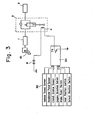
- a brake master cylinder 1 is actuated by a brake pedal 10.
- Numeral 2 denotes a brake oil cylinder
- numeral 3 designates an electromagnetic check valve disposed in a conduit brake interconnecting the / cylinder 2 and master cylinder 1.
- the arrangement thus far is similar to that of the above-described conventional apparatus and functions in a similar manner.
- the solenoid 4 is connected at one end to the storage battery 8.
- An electronic control unit 20 having a transistor TR controls the electromagnetic check valve 3 in accordance with output signals obtained from sensing means 30 for sensing the operating conditions of the vehicle.
- the latter includes a vehicle speed sensor for sensing the travelling speed of the vehicle, an accelerator pedal sensor for sensing the amount by which an accelerator pedal is depressed, a clutch stroke sensor for sensing the amount of engagement of a clutch, an engine rotation sensor for sensing engine rpm, a brake pedal switch for sensing whether or not the brake pedal is actuated, a gear position switch for sensing the gear position of the transmission, and a select position switch for sensing the operating positibn of a select lever.
- the electronic control unit 20 on the basis of the various output signals produced by the sensing means 30, actuates the solenoid 4 of the electromagnetic check valve 3 by a drive signal developed at the base of the transistor TR to close the electromagnetic valve 3 and to open the check valve 3 under predetermined conditions, thereby maintaining and removing the braking force depending upon the operating conditions of the vehicle.
- Fig. 4 is a view showing apparatus of the present invention applied to a vehicle having an automatic transmission. Portions similar to those shown in Fig. 3 are designated by like reference characters.
- the brake master cylinder 1 is actuated by the brake pedal 10.
- the electromagnetic check valve 3 having the solenoid 4 connected to the storage battery 8 is disposed in a conduit interconnecting the brake 40 cylinder 2 and the master cylinder 1.
- Numeral 51 denotes an engine having a throttle valve or a throttle actuator 51a for actuating a fuel injection pump.
- a clutch 52 composed of a well-known dry-type single-disk friction clutch is for transmitting the motive force of the engine 51 to, or for disconnecting the motive force from, a parallel shaft gear-type transmission 53.
- Numeral 54 denotes a clutch actuator for controlling the amount of engagement of the clutch 52 and having a hydraulic chamber which communicates via an electromagnetic valve 55 with a hydraulic mechanism 56 including a hydraulic pump 56a and a pressure oil tank 56b.
- a speed-change actuator 57 controls the shifting of gears within the transmission 53 and is connected to the hydraulic mechanism 56 to be hydraulically controlled thereby.
- Sensors include a vehicle speed sensor 31 disposed opposite the output shaft of the transmission 53, an accelerator pedal sensor 32 for sensing the amount of depression of an accelerator pedal 58, a clutch stroke sensor 33 mounted on the clutch actuator 54 for sensing the amount of engagement of the clutch 52, an engine rotation sensor 34 disposed opposite the flywheel of the engine 51 for sensing the engine rpm, a brake pedal switch 35 mounted on the brake pedal 10 for sensing whether or not the brake pedal is operated, a gear position switch 36 mounted on the transmission actuator 57 for sensing the gear position of the transmission 53, and a select position switch 37 for sensing a position selected by a select lever 59. Output signals from these sensors are applied to the electronic control unit 40, on the basis of which the control unit actuates the electromagnetic check valve 3 to maintain or release braking force.
- An automatic shifting operation performed by the arrangement of Fig. 4 takes place in the following manner.
- the electronic control unit 40 derives an optimum gear position and produces an output signal indicative thereof.
- the electromagnetic valve 55 is actuated in response to this signal and causes the clutch actuator 54 to disengage the clutch 52.
- the throttle actuator 51a is controlled to throttle back on the amount of fuel supplied.
- the electronic control unit 40 controls the transmission actuator 57, which responds by effecting a changeover from the present gear position to the optimum gear position derived in the manner described above.
- the electronic control unit 40 then controls the electromagnetic valve 55 to actuate the clutch actuator 54, thereby engaging the clutch 52 to complete the shifting operation.
- the electronic control unit 40 simultaneously operates the throttle actuator 51a by an amount corresponding to the amount of accelerator pedal depression.
- the electronic control unit 40 (20) turns on the electrbmagnetic check valve 3 to maintain the braking state only when the following conditions hold: (1) the position selected by the select lever 59 is other than neutral, (2) the vehicle speed is zero, i.e., the vehicle is at rest, (3) the transmission 53 is in low gear (ordinarily first gear), (4) the engine 51 is rotating, (5) the accelerator pedal 58 is not depressed, i.e., the amount of accelerator pedal depression is zero, and (6) the clutch stroke sensor 33 is in the off position, i.e., the clutch 52 is disengaged.
- the electromagnatic check valve 3 cuts off the passage introducing hydraulic pressure from the oil cylinder 2 to the master cylinder 1, so that the brake oil supplied to the oil cylinder 2 is kept within the oil cylinder. The braking state is thus maintained even when the driver removes his foot from the brake pedal 10.
- the electromagnetic valve 3 must be turned off to cancel the foregoing state, namely the state in which the braking force is maintained.
- the electronic control unit 40 (20) will accomplish this when the following conditions hold: (1) the select lever is in a position other than neutral, (2) the vehicle speed is zero, i.e., the vehicle is at rest, (3) the transmission is in a low gear (ordinarily first gear) at which the vehicle is capable of being started, (4) the engine is rotatingp (5) the accelerator pedal is depressed to turn on the accelerator pedal sensor, and the clutch actuator 54 is operated by depression of the accelerator pedal, and (6) the clutch stroke sensor is in the ON position.
- the electronic control unit 40 engages the clutch actuator in accordance with the amount of accelerator pedal depression.
- the electromagnetic check valve 3 is turned off.
- an electronic control unit controls an electromagnetic check valve, which is disposed in the fluid pressure circuit of a brake, on the basis of output signals from sensing means for sensing the operating conditions of the vehicle.
- a braking force applied to the vehicle is maintained or removed by the operation of the electromagnetic valve. Braking force at the time that the vehicle is started from rest can therefore be maintained in a precise manner to assure a smooth start, without backward movement of the vehicle, even when the vehicle is started on an upgrade.
- the present invention is applied to a hydraulic brake system.
- the invention is not limited to such application but can also be used in a vehicle having a pneumatic brake system.
- the electromagnetic check valve would be installed in a fluid pressure circuit heading from a brake valve, which is operated by the brake pedal, to an air chamber-type actuator for operating a brake mechanism.
Landscapes
- Engineering & Computer Science (AREA)
- Transportation (AREA)
- Mechanical Engineering (AREA)
- Regulating Braking Force (AREA)
- Braking Systems And Boosters (AREA)
Applications Claiming Priority (4)
| Application Number | Priority Date | Filing Date | Title |
|---|---|---|---|
| JP58117483A JPS6011719A (ja) | 1983-06-29 | 1983-06-29 | 制動力保持装置付電子自動変速装置 |
| JP117483/83 | 1983-06-29 | ||
| JP118459/83 | 1983-06-30 | ||
| JP58118459A JPS6012360A (ja) | 1983-06-30 | 1983-06-30 | 車両用制動装置 |
Publications (3)
| Publication Number | Publication Date |
|---|---|
| EP0131411A2 true EP0131411A2 (de) | 1985-01-16 |
| EP0131411A3 EP0131411A3 (en) | 1986-09-03 |
| EP0131411B1 EP0131411B1 (de) | 1989-12-27 |
Family
ID=26455581
Family Applications (1)
| Application Number | Title | Priority Date | Filing Date |
|---|---|---|---|
| EP84304342A Expired EP0131411B1 (de) | 1983-06-29 | 1984-06-27 | Bremssystem für Fahrzeug |
Country Status (7)
| Country | Link |
|---|---|
| US (1) | US4618040A (de) |
| EP (1) | EP0131411B1 (de) |
| KR (1) | KR890001648B1 (de) |
| AU (1) | AU557685B2 (de) |
| CA (1) | CA1236900A (de) |
| DE (1) | DE3480834D1 (de) |
| ES (1) | ES534151A0 (de) |
Cited By (12)
| Publication number | Priority date | Publication date | Assignee | Title |
|---|---|---|---|---|
| GB2167144A (en) * | 1984-11-14 | 1986-05-21 | Kia Motors Corp | Automatic control circuit for brake control devices |
| DE3618532A1 (de) * | 1985-06-03 | 1986-12-04 | Nissan Motor Co., Ltd., Yokohama, Kanagawa | Anfahrhilfe fuer ein fahrzeug fuer das anfahren an einer steigung und verfahren zum steuern der anfahrhilfe |
| US4676354A (en) * | 1984-11-23 | 1987-06-30 | Ab Volvo | Motor, brake and bearing controlled hill holder |
| EP0205322A3 (en) * | 1985-06-10 | 1987-08-19 | Isuzu Motors Limited | Method and apparatus for controlling an automatic clutch |
| DE3621076A1 (de) * | 1986-06-24 | 1988-01-14 | Opel Adam Ag | Bremsvorrichtung fuer fahrzeuge mit anfahrhilfevorrichtung |
| DE3719683A1 (de) * | 1986-06-12 | 1988-02-11 | Isuzu Motors Ltd | Steuervorrichtung zum aufrechterhalten der bremskraft fuer ein kraftfahrzeug |
| EP0280818A1 (de) * | 1986-12-27 | 1988-09-07 | Isuzu Motors Limited | Vorrichtung zur Aufrechthaltung der Bremskraft für ein Fahrzeug |
| DE9012523U1 (de) * | 1989-09-01 | 1990-11-15 | Hee, Nam Young, Seoul | Automobilbremssicherheitssystem |
| EP0533580A1 (de) * | 1991-09-20 | 1993-03-24 | Regie Nationale Des Usines Renault S.A. | Steuerungsverfahren für ein Fahrzeug mit automatischem oder halbautomatischem, gestuftem Getriebe |
| EP0839684A1 (de) * | 1996-11-05 | 1998-05-06 | MAGNETI MARELLI S.p.A. | System zur Steuerung des Parkens und des Startens am Berg eines Kraftfahrzeuges |
| EP0786368A3 (de) * | 1996-01-29 | 1998-12-30 | Toyota Jidosha Kabushiki Kaisha | Bremskraft-Steuerungsverfahren für Kraftfahrzeug mit Anfahrkupplung |
| DE10009748B4 (de) * | 1999-03-03 | 2018-01-25 | Honda Giken Kogyo K.K. | Bremsfluiddruck-Rückhalteeinheit |
Families Citing this family (16)
| Publication number | Priority date | Publication date | Assignee | Title |
|---|---|---|---|---|
| US4681196A (en) * | 1984-08-20 | 1987-07-21 | Allied Corporation | Control circuit for brake booster vehicular hill holder system |
| GB2174780B (en) * | 1985-04-11 | 1988-07-06 | Mitsubishi Motors Corp | Automatic transmission apparatus for vehicle |
| SE460781B (sv) * | 1988-03-31 | 1989-11-20 | Saab Scania Ab | Foerfarande och arrangemang foer konstantfarthaallning av motorfordon vid koerning i nedfoersbacken |
| DE3909907C2 (de) * | 1989-03-25 | 1997-03-13 | Bosch Gmbh Robert | Feststellbremse für Kraftfahrzeuge |
| US5983149A (en) * | 1991-04-08 | 1999-11-09 | Caterpillar Inc. | Automatic vehicle speed retarding control through actuation of wheel brakes |
| JP3528235B2 (ja) * | 1994-05-11 | 2004-05-17 | いすゞ自動車株式会社 | 自動変速装置 |
| FR2722466B1 (fr) * | 1994-07-13 | 1996-10-11 | Henri Bonnard | Dispositif de double commande agissant a la demande sur le freinage et/ou sur l'embrayage et/ou sur l'accelerateur d'un vehicule ecole |
| DE19611359C1 (de) * | 1996-03-22 | 1997-08-28 | Daimler Benz Ag | Verfahren zum Verhindern unbeabsichtigten Wegrollens eines Fahrzeugs |
| DE19630871A1 (de) * | 1996-07-31 | 1998-02-05 | Bayerische Motoren Werke Ag | Verfahren zum kurzzeitigen Anhalten eines Fahrzeuges |
| DE19931345A1 (de) * | 1999-06-10 | 2000-12-14 | Continental Teves Ag & Co Ohg | Vorrichtung sowie Verfahren für die fahrsituationsabhängige Betätigung einer Bremsanlage eines Kraftfahrzeuges |
| BR0110807A (pt) * | 2000-05-17 | 2003-02-11 | Luk Lamellen & Kupplungsbau | Processo e dispositivo para o acionamento automático de um freio de veìculo |
| JP4060537B2 (ja) * | 2001-02-07 | 2008-03-12 | 株式会社エクセディ | 車輌の補助ブレーキシステム |
| DE102006002900B4 (de) * | 2006-01-20 | 2007-12-20 | Siemens Ag | Elektrische Maschine mit einem dreisträngigen Wicklungssystem |
| JP5408855B2 (ja) * | 2007-08-28 | 2014-02-05 | 株式会社デンソー | 車両用制御装置及び制御システム |
| DE102016201179B4 (de) * | 2016-01-27 | 2021-04-15 | Ford Global Technologies, Llc | Verfahren zum Betreiben eines Bremssystems eines Kraftfahrzeugs sowie Bremssystem für ein Kraftfahrzeug |
| US12252105B2 (en) * | 2020-12-14 | 2025-03-18 | Ford Global Technologies, Llc | Hill-hold assist |
Family Cites Families (14)
| Publication number | Priority date | Publication date | Assignee | Title |
|---|---|---|---|---|
| FR866652A (fr) * | 1939-08-15 | 1941-08-25 | Bendix Aviat Corp | Dispositif perfectionné de commande pour véhicules automobiles |
| US2849557A (en) * | 1954-10-11 | 1958-08-26 | Bendix Aviat Corp | Anti-creep accelerator switch |
| US3127966A (en) * | 1958-08-22 | 1964-04-07 | Holland | Accelerator pedal controlled brake system |
| FR1231678A (fr) * | 1958-12-05 | 1960-09-30 | Dispositif de blocage et de déblocage automatique d'une transmission mécanique ou hydraulique pour véhicules automobiles | |
| US3705643A (en) * | 1969-06-27 | 1972-12-12 | Toyoda Automatic Loom Works | Brake & clutch control for industrial track |
| DE2425863A1 (de) * | 1974-05-28 | 1975-12-11 | Schneider | Kraftfahrzeug |
| JPS52127559A (en) * | 1976-04-19 | 1977-10-26 | Nissan Motor Co Ltd | Electronic parallel shaft automatic transmission gear box |
| US4163586A (en) * | 1977-11-25 | 1979-08-07 | Motor Wheel Corporation | Control system for double-actuator brakes |
| US4273224A (en) * | 1978-10-11 | 1981-06-16 | Towmotor Corporation | Vehicle control system with conditional transmission-brake interlock |
| US4262783A (en) * | 1979-07-31 | 1981-04-21 | Scarrott Gordon G | Vehicle propulsion control systems |
| EP0067190A1 (de) * | 1980-12-19 | 1982-12-22 | Hugh-Peter Granville Kelly | Einrichtung um ein fahrzeug unbeweglich zu halten |
| AU7324381A (en) * | 1981-04-20 | 1982-11-04 | Fail Safe Industries Inc. | Control system for vehicle brake valve |
| US4518067A (en) * | 1982-01-22 | 1985-05-21 | Transtech Industrial Corporation | Automobile brake device |
| US4487303A (en) * | 1982-12-27 | 1984-12-11 | Ford Motor Company | Automatic transmission start-up clutch control system |
-
1984
- 1984-06-21 AU AU29723/84A patent/AU557685B2/en not_active Ceased
- 1984-06-22 CA CA000457169A patent/CA1236900A/en not_active Expired
- 1984-06-27 EP EP84304342A patent/EP0131411B1/de not_active Expired
- 1984-06-27 US US06/625,010 patent/US4618040A/en not_active Expired - Lifetime
- 1984-06-27 DE DE8484304342T patent/DE3480834D1/de not_active Expired - Fee Related
- 1984-06-29 KR KR1019840003749A patent/KR890001648B1/ko not_active Expired
- 1984-06-29 ES ES534151A patent/ES534151A0/es active Granted
Cited By (16)
| Publication number | Priority date | Publication date | Assignee | Title |
|---|---|---|---|---|
| GB2167144A (en) * | 1984-11-14 | 1986-05-21 | Kia Motors Corp | Automatic control circuit for brake control devices |
| US4676354A (en) * | 1984-11-23 | 1987-06-30 | Ab Volvo | Motor, brake and bearing controlled hill holder |
| DE3618532A1 (de) * | 1985-06-03 | 1986-12-04 | Nissan Motor Co., Ltd., Yokohama, Kanagawa | Anfahrhilfe fuer ein fahrzeug fuer das anfahren an einer steigung und verfahren zum steuern der anfahrhilfe |
| US4732248A (en) * | 1985-06-10 | 1988-03-22 | Isuzu Motors Limited | Method of and apparatus for controlling automatic clutch |
| EP0205322A3 (en) * | 1985-06-10 | 1987-08-19 | Isuzu Motors Limited | Method and apparatus for controlling an automatic clutch |
| DE3719683A1 (de) * | 1986-06-12 | 1988-02-11 | Isuzu Motors Ltd | Steuervorrichtung zum aufrechterhalten der bremskraft fuer ein kraftfahrzeug |
| EP0251156A3 (en) * | 1986-06-24 | 1989-02-22 | Adam Opel Aktiengesellschaft | Braking system for a motor vehicle |
| DE3621076A1 (de) * | 1986-06-24 | 1988-01-14 | Opel Adam Ag | Bremsvorrichtung fuer fahrzeuge mit anfahrhilfevorrichtung |
| EP0280818A1 (de) * | 1986-12-27 | 1988-09-07 | Isuzu Motors Limited | Vorrichtung zur Aufrechthaltung der Bremskraft für ein Fahrzeug |
| US4865175A (en) * | 1986-12-27 | 1989-09-12 | Isuzu Motors Limited | Device for holding braking force for vehicle |
| DE9012523U1 (de) * | 1989-09-01 | 1990-11-15 | Hee, Nam Young, Seoul | Automobilbremssicherheitssystem |
| EP0533580A1 (de) * | 1991-09-20 | 1993-03-24 | Regie Nationale Des Usines Renault S.A. | Steuerungsverfahren für ein Fahrzeug mit automatischem oder halbautomatischem, gestuftem Getriebe |
| FR2681561A1 (fr) * | 1991-09-20 | 1993-03-26 | Renault | Procede de commande d'un vehicule equipe d'un mecanisme de transmission automatique ou semi-automatique a rapports etages ou non. |
| EP0786368A3 (de) * | 1996-01-29 | 1998-12-30 | Toyota Jidosha Kabushiki Kaisha | Bremskraft-Steuerungsverfahren für Kraftfahrzeug mit Anfahrkupplung |
| EP0839684A1 (de) * | 1996-11-05 | 1998-05-06 | MAGNETI MARELLI S.p.A. | System zur Steuerung des Parkens und des Startens am Berg eines Kraftfahrzeuges |
| DE10009748B4 (de) * | 1999-03-03 | 2018-01-25 | Honda Giken Kogyo K.K. | Bremsfluiddruck-Rückhalteeinheit |
Also Published As
| Publication number | Publication date |
|---|---|
| CA1236900A (en) | 1988-05-17 |
| AU557685B2 (en) | 1987-01-08 |
| ES8505301A1 (es) | 1985-05-16 |
| EP0131411A3 (en) | 1986-09-03 |
| AU2972384A (en) | 1985-01-03 |
| EP0131411B1 (de) | 1989-12-27 |
| KR890001648B1 (ko) | 1989-05-12 |
| US4618040A (en) | 1986-10-21 |
| DE3480834D1 (de) | 1990-02-01 |
| ES534151A0 (es) | 1985-05-16 |
| KR850000325A (ko) | 1985-02-26 |
Similar Documents
| Publication | Publication Date | Title |
|---|---|---|
| EP0131411B1 (de) | Bremssystem für Fahrzeug | |
| US4558612A (en) | Vehicular automatic speed change gear assembly | |
| JPS63166643A (ja) | 車両の制動力保持装置 | |
| US4821854A (en) | Brake force retaining control apparatus | |
| GB1529480A (en) | Control system for an automatic power transmission | |
| US4056176A (en) | Drive arrangement for motor vehicles, especially for passenger motor vehicles, with an automatic change-speed transmission | |
| JPS6012360A (ja) | 車両用制動装置 | |
| GB1413631A (en) | Driving systems for motor vehicles | |
| CA1258217A (en) | Brake control device | |
| JP4454259B2 (ja) | ブレーキ液圧保持装置 | |
| JPH0568396B2 (de) | ||
| JPS6136046A (ja) | 制動油圧保持装置の作動解除方式 | |
| JP2711753B2 (ja) | 坂道発進補助装置 | |
| JPH0310112Y2 (de) | ||
| JPH0790735B2 (ja) | 車両の自動変速制御装置 | |
| JPH0642902Y2 (ja) | 坂道発進の制御装置 | |
| JPH062829Y2 (ja) | 車両の発進制御装置 | |
| JPH0613413Y2 (ja) | 自動車の自動変速機の制御装置 | |
| JPH04290663A (ja) | 自動変速機の制御装置 | |
| JPH0434013B2 (de) | ||
| WO1996010492A2 (en) | Improvements in transmission systems for vehicles | |
| JPH0520595Y2 (de) | ||
| JPH0520594Y2 (de) | ||
| JPH0112692B2 (de) | ||
| JPS61129356A (ja) | パ−キングブレ−キ装置 |
Legal Events
| Date | Code | Title | Description |
|---|---|---|---|
| PUAI | Public reference made under article 153(3) epc to a published international application that has entered the european phase |
Free format text: ORIGINAL CODE: 0009012 |
|
| AK | Designated contracting states |
Designated state(s): CH DE FR GB IT LI SE |
|
| PUAL | Search report despatched |
Free format text: ORIGINAL CODE: 0009013 |
|
| AK | Designated contracting states |
Kind code of ref document: A3 Designated state(s): CH DE FR GB IT LI SE |
|
| 17P | Request for examination filed |
Effective date: 19861202 |
|
| 17Q | First examination report despatched |
Effective date: 19880108 |
|
| GRAA | (expected) grant |
Free format text: ORIGINAL CODE: 0009210 |
|
| AK | Designated contracting states |
Kind code of ref document: B1 Designated state(s): CH DE FR GB IT LI SE |
|
| REF | Corresponds to: |
Ref document number: 3480834 Country of ref document: DE Date of ref document: 19900201 |
|
| ET | Fr: translation filed | ||
| ITF | It: translation for a ep patent filed | ||
| PLBE | No opposition filed within time limit |
Free format text: ORIGINAL CODE: 0009261 |
|
| STAA | Information on the status of an ep patent application or granted ep patent |
Free format text: STATUS: NO OPPOSITION FILED WITHIN TIME LIMIT |
|
| 26N | No opposition filed | ||
| ITTA | It: last paid annual fee | ||
| EAL | Se: european patent in force in sweden |
Ref document number: 84304342.3 |
|
| PGFP | Annual fee paid to national office [announced via postgrant information from national office to epo] |
Ref country code: FR Payment date: 20010511 Year of fee payment: 18 |
|
| PGFP | Annual fee paid to national office [announced via postgrant information from national office to epo] |
Ref country code: SE Payment date: 20010517 Year of fee payment: 18 Ref country code: CH Payment date: 20010517 Year of fee payment: 18 |
|
| PGFP | Annual fee paid to national office [announced via postgrant information from national office to epo] |
Ref country code: GB Payment date: 20010518 Year of fee payment: 18 |
|
| PGFP | Annual fee paid to national office [announced via postgrant information from national office to epo] |
Ref country code: DE Payment date: 20010523 Year of fee payment: 18 |
|
| REG | Reference to a national code |
Ref country code: GB Ref legal event code: IF02 |
|
| PG25 | Lapsed in a contracting state [announced via postgrant information from national office to epo] |
Ref country code: GB Free format text: LAPSE BECAUSE OF NON-PAYMENT OF DUE FEES Effective date: 20020627 |
|
| PG25 | Lapsed in a contracting state [announced via postgrant information from national office to epo] |
Ref country code: SE Free format text: LAPSE BECAUSE OF NON-PAYMENT OF DUE FEES Effective date: 20020628 |
|
| PG25 | Lapsed in a contracting state [announced via postgrant information from national office to epo] |
Ref country code: LI Free format text: LAPSE BECAUSE OF NON-PAYMENT OF DUE FEES Effective date: 20020630 Ref country code: CH Free format text: LAPSE BECAUSE OF NON-PAYMENT OF DUE FEES Effective date: 20020630 |
|
| PG25 | Lapsed in a contracting state [announced via postgrant information from national office to epo] |
Ref country code: DE Free format text: LAPSE BECAUSE OF NON-PAYMENT OF DUE FEES Effective date: 20030101 |
|
| EUG | Se: european patent has lapsed | ||
| REG | Reference to a national code |
Ref country code: CH Ref legal event code: PL |
|
| GBPC | Gb: european patent ceased through non-payment of renewal fee |
Effective date: 20020627 |
|
| PG25 | Lapsed in a contracting state [announced via postgrant information from national office to epo] |
Ref country code: FR Free format text: LAPSE BECAUSE OF NON-PAYMENT OF DUE FEES Effective date: 20030228 |
|
| REG | Reference to a national code |
Ref country code: FR Ref legal event code: ST |