EP0132023A2 - Transmission planétaire à changement de vitesses - Google Patents
Transmission planétaire à changement de vitesses Download PDFInfo
- Publication number
- EP0132023A2 EP0132023A2 EP84303183A EP84303183A EP0132023A2 EP 0132023 A2 EP0132023 A2 EP 0132023A2 EP 84303183 A EP84303183 A EP 84303183A EP 84303183 A EP84303183 A EP 84303183A EP 0132023 A2 EP0132023 A2 EP 0132023A2
- Authority
- EP
- European Patent Office
- Prior art keywords
- shaft
- ring gear
- gear
- fixed
- transmission
- Prior art date
- Legal status (The legal status is an assumption and is not a legal conclusion. Google has not performed a legal analysis and makes no representation as to the accuracy of the status listed.)
- Withdrawn
Links
Images

Classifications
-
- F—MECHANICAL ENGINEERING; LIGHTING; HEATING; WEAPONS; BLASTING
- F16—ENGINEERING ELEMENTS AND UNITS; GENERAL MEASURES FOR PRODUCING AND MAINTAINING EFFECTIVE FUNCTIONING OF MACHINES OR INSTALLATIONS; THERMAL INSULATION IN GENERAL
- F16H—GEARING
- F16H3/00—Toothed gearings for conveying rotary motion with variable gear ratio or for reversing rotary motion
- F16H3/44—Toothed gearings for conveying rotary motion with variable gear ratio or for reversing rotary motion using gears having orbital motion
- F16H3/78—Special adaptation of synchronisation mechanisms to these gearings
-
- F—MECHANICAL ENGINEERING; LIGHTING; HEATING; WEAPONS; BLASTING
- F16—ENGINEERING ELEMENTS AND UNITS; GENERAL MEASURES FOR PRODUCING AND MAINTAINING EFFECTIVE FUNCTIONING OF MACHINES OR INSTALLATIONS; THERMAL INSULATION IN GENERAL
- F16H—GEARING
- F16H3/00—Toothed gearings for conveying rotary motion with variable gear ratio or for reversing rotary motion
- F16H3/44—Toothed gearings for conveying rotary motion with variable gear ratio or for reversing rotary motion using gears having orbital motion
- F16H3/46—Gearings having only two central gears, connected by orbital gears
- F16H3/48—Gearings having only two central gears, connected by orbital gears with single orbital gears or pairs of rigidly-connected orbital gears
- F16H3/52—Gearings having only two central gears, connected by orbital gears with single orbital gears or pairs of rigidly-connected orbital gears comprising orbital spur gears
- F16H3/54—Gearings having only two central gears, connected by orbital gears with single orbital gears or pairs of rigidly-connected orbital gears comprising orbital spur gears one of the central gears being internally toothed and the other externally toothed
Definitions
- the present invention relates to a change gear planetary transmission, also referred to as an epicyclic transmission. More particularly, the present invention relates to a change gear planetary transmission having an input and an output shaft in substantially coaxial and adjacent end-to-end relationship and selectively shiftable between an indirect ratio (i.e. a ratio wherein the output shaft is driven at a different speed, usually a reduced speed, than the input shaft speed) and a direct ratio (i.e. a ratio wherein the output shaft is driven at the same rotational speed as the input shaft).
- the sun gear rotates with the input shaft
- the carrier of the multiple planet gears rotates with the output shaft and the indirect ratio is obtained by rotationally fixing the ring gear or annulus to the transmission housing or another member rotatable relative to the input and output shafts.
- Planetary or epicyclic change gear transmissions of the type utilizing single, multiple and/or compound planetary gearing systems comprising a central or sun gear meshingly engaged with multiple planet gears carried by a planet carrier which planet gears are in turn meshed with an annulus or ring gear are well known in the prior art and examples thereof may be seen by reference to United States Patent Nos. 2,598,179; 3,365,985; 3,772,940; 4,103,753; 4,189,960; ' and 4,347,762, the disclosures of all of which are hereby incorporated by reference.
- one of the planetary elements is typically fixed to rotate with an input member, another of the elements is typically fixed to rotate with an output member and a third element is selectively clutched, either by positive clutch or friction clutch means, to a casing or the like to obtain an indirect ratio or to one of the other elements to obtain a direct ratio.
- Two speed planetary change gear transmissions having a direct ratio and an indirect ratio are well known in the prior art. Such transmissions may act independently to provide a selected one of two drive ratios between an input and an output member, such as when utilized as a wheel end hub drive, or may be utilized in series connection with a multi-speed change gear transmission section as the range or splitter section of a multi-speed compound transmission.
- the planetary change gear transmission of the present invention is especially well suited for, but not necessarily limited to, use in cooperation with an ordinary multi-speed change gear transmission section as the splitter or range auxiliary section therefor.
- the transmission or gear train especially when utilized as a transmission for a vehicle such as a heavy over-the-road truck, may often be in the direct mode or drive ratio for at least 80% of the time.
- the geartooth forces are transferred, in the direct mode, by the planet spindle needle roller bearings while they are not rolling. High loads in the direct ratio can cause the static rollers to give rise to brinelling of the needle bearing raceway. For this and other reasons, it is desired to reduce the torque load, for given output torque, exerted on the planetary carrier and its components in the direct drive mode of operation of the change gear planetary transmission.
- the drawbacks of the prior art have been minimized by the provision of a two speed change gear planetary transmission having a selectable direct and indirect ratio of a structure which reduces the loads on the transmission components considerably, leading to better durability and/or the possibility of using smaller less expensive planet wheel bearings and other planetary components of structures.
- the change gear planetary transmission,of the present invention also allows reduction of costs and physical length of the transmission and allows the transmission housing or casing to be simplified since an intermediate plate to support a synchronizing clutch structure for the direct drive mode of operation is not required.
- the degree of beneficial reductions of loads and forces obtained by the structure of the present invention depends, of course, upon the specific ratio of the planetary transmission, which ratio is typically in the range of 3.5:1 overall. Such a ratio requires a ring gear with a pitch circle radius (PCR) 2.5 times that of the sun gear.
- F 1 the tooth force in the present invention
- F 2 the beneficial reduction may be expressed:
- F l/ F 2 PCR sun gear/(PCR sun gear and PCR ring gear)
- the above is accomplished by providing a two speed change gear planetary transmission wherein the ring gear is not coupled to the output shaft for the direct drive mode of operation. Instead, the ring gear or annulus is engaged to rotate rigidly with the input shaft whenever direct drive is needed.
- the ring gear according to an important aspect of the present invention, is axially slideable relative to the planet gears while remaining in the usual constant engagement therewith so as to engage and lock to an externally toothed wheel or clutch plate rotating with the sun gear and the input shaft.
- the ring gear or annulus will preferably, but not necessarily, employ the same internal gear teeth that engage the planet gears for the inventive lockup to the input shaft, thus causing a one-to-one or direct drive mode of operation.
- the change gear planetary transmission of the present invention comprises a clutch member carrying external clutch teeth or splines fixed for rotation with the input shaft and sun gear, an annulus or ring gear constantly meshed or engaged with a set of planet gears and axially slideable between two axial positions for engaging and not engaging, respectively said externally toothed clutch member, and a synchronizer operative to frictionally couple the ring gear respectively to the planet carrier (or to the output shaft, or to the coupling member connecting the planet carrier to the output shaft) and to the relatively fixed casing or another member rotatable relative to the input and output shafts.
- the ring gear or annulus of the planetary of epicyclic gear transmission is fixed for axial movement with a bi-directional clutch sleeve engageable by conventional shifting means such as shift forks, yokes or the like.
- the annulus or ring gear may be joined to the synchronizer clutch sleeve by means of electron welding or the like.
- the synchronizer clutch accellerates the ring gear and synchronizer sleeve until their speed is substantially synchronous with that of the planet carrier.
- the planet gears become stationary on their own axes and hence the sun gear and input shaft are forced to rotate at the same speed as the planet carrier and the ring gear.
- the ring gear moves into positive engagements with the teeth of the clutch ring fitted to the input shaft.
- the synchronizer will retard the rotational movement of the ring gear relative to the transmission housing allowing the ring gear to positively engage a second, indirect ratio clutch member fixed to the housing.
- Another object of the present invention is to provide a new and improved change gear planetary transmission of the type having a sun gear fixed for rotation with the input shaft and a planetary carrier fixed for rotation with the output shaft, wherein the forces exerted upon the planet gears in the direct mode of operation of transmission are minimized.
- a further object of the present invention is to provide a new and improved two speed change gear planetary transmission of the type having a direct and an indirect mode of operation wherein the sun gear is fixed for rotation with the input shaft, the planet carrier is fixed for rotation with the output shaft, and the ring gear is selectively axially moveable relative to the sun gear and the planet carrier to positively engage, one at a time, a clutch member fixed for rotation with the input shaft and a clutch member fixed to the transmission housing.
- Both the prior art two-speed change gear planetary transmission and the two-speed change gear planetary transmission of the present invention are illustrated, and are particularly well suited as, auxiliary transmission sections of compound transmissions wherein the auxiliary sections are connected in series with the main transmission sections as well known in the Prior Art.
- the change speed planetary transmission of the present invention is not limited to such applications.
- Both the prior art and the present invention are illustrated as transmissions having a speed reduction ratio and a direct drive ratio wherein the sun gear is fixed for rotation with the input shaft and the planet carrier is fixed for rotation with the output shaft. It is understood, however, that the present invention is also suited for those types of gear drives wherein the planet carrier is fixed to the input shaft and the sun gear fixed for rotation with the output shaft.
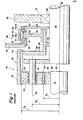
- Transmission 10 includes an input shaft 12 and an output shaft 14, both independently rotatable about an axis of rotation 16 relative to a transmission housing or casing 18.
- the inner ends 20 and 22 of the shafts 12 and 14, respectively, are arranged in near or abutting end-to-end relationship.
- Dutput shaft 14 is supported for rotation within housing 18 by means of several bearings, only one of which, 24, is illustrated.
- input shaft 12 of planetary change gear transmission 10 is integral with or driven by the output shaft (not shown) of a conventional change speed main transmission section (not shown).
- Input shaft 12 is drivingly connected to the output shaft 14 by means of planetary change speed gearing 26.
- the planetary gearing 26 comprises a sun gear 28 fixed for rotation with input shaft 12 and carrying external gear teeth defining a pitch radius R S , a plurality, usually three of more (only one of which is shown in Figure 1), of planet gears 30 constantly meshed with sun gear 28 and supported for rotation about their axes 32 on planet shafts 34 which planet shafts 34 are supported on a disc type planet carrier 36 fixed for rotation with the output shaft 22 and an internally tooth annulus or ring gear 38 the teeth of which are constantly meshed with the teeth of the planet gears 30 and which internal teeth define a pitch circle radius R R .
- the axes of the planet shafts 34 define a radius Rp from the axis of rotation 16 of shafts 12 and 14.
- gears 28, 30 and 38 are axially fixed relative to the shafts 12 and 14 and the housing 18 by conventional means (not shown) and the planet gears 30 are supported for rotation about the planet shafts 34 by needle roller bearings 40.
- the indirect mode of operation may be obtained by locking the ring gear to a member rotatable relative to the input and output shafts. Typically, such a member is rotated at a speed different from the rotational speed of the input shaft.
- Shifting of transmission 10 between its indirect ratio mode and its direct ratio mode is accomplished by rotationally fixing ring gear 38 to transmission housing 18 or to output shaft 14, respectfully, by means of a shifting mechanism indicatd generally at 46.
- Shifting mechanism 46 includes an indirect ratio positive clutch and synchronizing cone structure 48 fixed to housing portion 44 and a direct ratio positive clutch and synchronizing cone structure 50 fixed for rotation with the output shaft 14 by means of a ring or disc-like coupling member 51.
- a ring gear coupling or connecting member 52 is rotationally supported at an axially extending generally tubular portion 54 on output shaft 14 by means of bearings 56 and includes a radially extending portion 58 by which the ring gear 38 is rotationally and axially fixed thereto as at mating splines 60.
- Bearing 56 may also provide some mounting support for rotation of the ring gear 38.
- a bi-directional sliding clutch member 62 is rotationally supported on a radial web member 64 fixed to the axially extending tubular portion 54 of the ring gear connecting member 52. Accordingly, sliding clutch member 62 is fixed for rotation with the ring gear 38.
- Sliding clutch member 62 is provided with a groove 66 for receipt of a shifting means such as a well known shift fork or yoke (not shown).
- the sliding clutch member 62 is provided with internal clutch teeth or splines 68 for cooperatin with external splines 70 on the web member 64 and for further cooperation with the external clutch teeth 71 and 72 of the synchro cone 74 and indirect clutch member 48.
- sliding clutch 66 may be moved axially to the left to positively engage indirect clutch 48 to rotationally fix the ring gear 38 to the housing 18 or may be moved axially to the right to positively engage direct clutch 50 to rotationally fix ring gear 38 to the output shaft 14.
- the sun gear 28, the planet carrier 36, the ring gear 38, the connecting member 52 and the output shaft 14 are all rotating at the same speed and the input torque is transmitted to the planet shafts 34 via the planet gears 30 which are rotationally fixed on the rotational axes 32.
- the fixed needle roller bearings 40 each tend to press against one portion of the planet shafts 34, usually a bearing race, and to brinel it.
- the ring gear 38 is caused by the reaction forces to be urged to rotate in the opposite direction of rotation which tendency is affectively prevented by the coupling member 52 which is fixed for rotation of the output shaft 14.
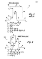
- This mode of operation is schematically and algebraically illustrated in Figure 2.
- the input torque T 1 applied to the input shaft 12 becomes the output torque TO applied to that portion of the output shaft 14 to the right of the connection with web member 51.
- Output shaft 14 has a higher torque T 3 applied thereto to the left of the junction of web member 51 and all this is supplied by the forces 2F 2 through the various planet shafts 34. T 3 exceeds TO by the torque T 2 which is applied via member 52 to the ring 38.
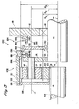
- Planetary change speed transmission 100 includes an input shaft 12 arranged coaxially with an output shaft 14 for independent rotation about an axis of rotation 16 relative to a transmission housing or casing 18 a portion of which, 42 is illustrated.
- Output shaft 14 is supported for rotation in housing 18 be means of bearing 24.
- the inner ends'20 and 22 of shafts 12 and 14, respectively, are arranged in close or axially abutting relationship., It is understood, as is well known in the art, that one of the shaft ends 20 or 22 may be provided with a necked down portion to be received within a pocket provided in the adjacent end of the other shaft.
- Planetary gearing 102 includes a sun gear 104 fixed for rotation to input shaft 12 as at internal splines 106 mating with external splines 108 provided on the input shaft 12.
- the sun gear 104 carries external gear teeth defining a pitch radius R S constantly meshed with the gear teeth of a plurality (only one of which is shown) of planet gears 110.
- the planet gears l10 are supported for rotation about their axes 112 on planet shafts 114 by means of needle roller bearings 40.
- the planet shafts 114 are carried by a disc or platelike planetary carrier 116 for rotation about axis of rotation 16 at a radius Rp.
- Planet carrier 116 and the planet shafts 114 are fixed for rotation about axis 16 with the output shaft 14 as at the splined connection 118.
- the sun gear 104 and the planet gears 110 are axially fixed relative to the housing 18 and the shafts 12 and 14 by conventional means.
- the planet gears 110 are constantly meshed with an annulus or ring gear 120 provided with an annular array of internal gear teeth 122.
- ring gear 120 is axially moveable relative to the planet gears 110 but will remain in meshing engagement therewith for all axial positions thereof.
- change speed transmission 100 has two selectable operating modes, namely an indirect operating mode wherein the ring gear 120 is rotationally fixed to the housing 18 (or some other member rotatable relative to the input and output shafts) and a direct mode wherein ring gear 120 is rotationally fixed to either the input shaft or the output shaft 14 to lockup the planetary gearing.
- an indirect operating mode wherein the ring gear 120 is rotationally fixed to the housing 18 (or some other member rotatable relative to the input and output shafts)
- ring gear 120 is rotationally fixed to either the input shaft or the output shaft 14 to lockup the planetary gearing.
- the ring gear 120 is rotationally fixed to the input shaft 12, the importance of which is discussed in detail below.
- Shifting mechanism 124 includes a radially extending disc or ring member 126 axially and rotationally fixed to the input shaft 12 and carrying direct clutch teeth 128 at the outer radially periphery thereof.
- Clutch teeth 128 are preferably of substantially the same profile as the gear teeth of planet gears 110 and define a pitch radius of R relative to the axis of rotation 16 for selective engagement by the teeth 122 of ring gear 120 to rotationally fix the ring gear to the input shaft.
- the shifting mechanism also includes a direct clutch and synchronizing cone mechanism 130 fixed to the housing 18 and including a conical synchronizing portion 132 and clutch teeth 134.
- a slider member 136 is rotationally fixed to a radially extending connecting disc member 138 supported for rotation on and relative to output shaft 14 by known means such as bearing 140.
- Slider member 136 defines internal splines 142 which mate with external splines 144 carried by the support member 138. As will be seen, the splines 142 also serve as positive clutch teeth.
- the slider member 136 includes a groove 66 for engagement by a shift fork 146 fixed for axial movement with a shift rod or shift piston 148.
- the slide member 136 is attached to the axially moveable ring gear 120 for axial and rotational movement therewith which connection may include a spline and then electron-welded connection, a pin connection or the like.
- the connecting disc member 138 may provide a degree of rotational support for the ring gear 120 in the same manner as connecting portion 58 provided a degree of rotational support for ring gear 38 in the prior art transmission 10 described above.
- the slide member 136 and ring gear 120 are moved axially rightwardly from the position shown causing the internal spline teeth 142 of slide member 136 to engage the spline teeth 150 of indirect synchro cone 152 which will decelerate the slide member and ring gear 120 to a halt relative to housing 18 allowing the internal clutch teeth 142 to positively engage direct clutch teeth 134 of direct clatch member 130 to rotationally fix the slide membe: and ring gear to the housing.
- the slide member 136 d ring gear 120 fixed thereto is moved axially lef: ardly towards the position shown in Figures 3 and 5 caus ng the internal clutch teeth l42 of the slide membe: 135 to engage the teeth 154 of direct synchro cone 256 bringing the synchro cone into frictional contact with a conical surface 158 provided on planet carrier 116.
- the synchro cone 156 will accelerate the slide member 136 and ring gear 120 to match the speed of the output shaft 12, prior to permitting clutch teeth 142 to pass through clutch 156 and the internal gear teeth 122 of ring gear member 120 may be engaged with external clutch teeth 128 of ring member 126 to lock the ring gear 120 rotatinally to the input shaft 12 to achieve the direct drive mode of operation of transmission 100.
- a spring biased detent ball 160 may be provided in the rotational support carrier 138 and a complementary detent groove 162 provided in slide member 136 positioning the slide member 135 and ring gear 120 in a position wherein ring gear 120 is not engaged to indirect clutch member 134 nor direct clutch member 128. In such a position, if resistance to rotation of the output shaft 14 exceeds resistance to rotation of the rotationally free ring gear 120, rotation of the input shaft 12 will result in rotation of the ring gear 120 and not rotation of output shaft 14.
- the support member 138 is constantly supporting slide member 136 in all axial positions thereof providing continuous rotational support for the ring gear 120.
- the output shaft 14 may be considerably reduced in axial length for conservation of material, weight, axial space and to provide a shorter and thus less distortable output shaft.
- gear tooth profiles and/or clutch tooth profiles may be of any conventional form.
- a significant advantage of the present invention is the reduction of forces on the planet gear portion of the planetary gearing 102 in the direct drive mode of operation of transmission 100, which reduction in forces results in a reduced tendancy of brinelling of the planet gear support surfaces of the planetary shafts 114.
- Figure 4 is a schematic force diagram for the transmission 100 in the direct drive mode of operation thereof and the calculations therefor taken in comparison with the similar diagram and calculations seen in Figure 2 for the direct drive mode of operation of the prior art transmission.
- the direct drive from input shaft 12.to output shaft 14 is actually via two routes.
- the sun gear 104 drives the locked planet gears 110 and thus their plant shafts 114 and planet carrier 116.
- the lockup member 126 drives the ring gear 120 and hence also shafts l14 and planet carrier 116.
- the loads on the planet gear teeth at their meshing engagement with both the ring gear 120 and the sun gear 104 are F l , and thus can be taken to provide a resulted load at pinion shaft 114 of 2F l as Rp equals the sum of R R plus R S divided by two.
- 2F l is a measure of the tendancy or brinelling during direct drive with no relative movements at the planet shaft bearings 40. Since the output torque T O is produced by 2F 1 , at the planet wheel center which is at a distance R P from the axis of rotation 16, we can represent T 0 as equal to 2F I R P which is equal to F 1 (R S + R R ).
- the forces carried by the planet gear shaft 34 in the direct mode of operation of prior art transmission 10 may be expressed as 2F 2 while the forces carried by the planetary gear shafts 114 in the transmission 100 of the present invention in the direct drive mode of operation thereof may be expressed as 2F 1 .
- the advantage factor of transmission 100 relative to prior art transmission 10 may be expressed as F 1 divided by F 2 which equals (T 1 /R R + RS)/(T 1 /R S ) which in turn equals R S /(R R + R S ) which, as indicated above, is typically in the range of 3.5 to 1.
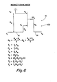
- a force diagram and the calculations therefor for both the transmission 100 of the present invention and the prior art transmission 10 may be seen by reference to Figure 6.
- the force transmitted by the planet carrier is increased by a factor equal to the reduction gearing ratio as compared to the force transmitted by the planet carrier in the direct drive mode of transmission 100 of the present invention.
- the increased forces transmitted by the planet carrier in the indirect mode versus the direct drive mode of transmission 100 is not considered to be a matter for concern as the planet gears 110 and bearings 40 supporting same on the planet gear shafts 114 are in relative rotation and thus the tendancy to cause brinelling of the planet gear shafts is greatly reduced or eliminated.
- a mounting flange 170 may be securred to the threaded outer end of the output shaft 14 by means of a nut 172 and a lock washer 174.
- Mounting flange 170 is rotationally fixed to output shaft 14 as is shown.
- Threaded members 180 may be utilized to rotationally fix the direct drive clutch member 130 to the housing 18.
- a nut 182 and a spacer member 184 may be utilized to axially fix the sun gear 104 and the locking member 126 on the input shaft 12.
- the means to rotationally fix the ring gear to one of the other elements of the planetary gear system to achieve the direct drive mode of transmission 100 is locking member 126 carrying clutch teeth 128 which clutch teeth when engaged with the ring gear will rotationally lock the ring gear to the sun gear 104 and input shaft 12 and which member 126 is physically located at the input end of the transmission on the input shaft 12 and spaced axially toward to input end of the input shaft from the sun gear 104.
Landscapes
- Engineering & Computer Science (AREA)
- General Engineering & Computer Science (AREA)
- Mechanical Engineering (AREA)
- Structure Of Transmissions (AREA)
Applications Claiming Priority (2)
| Application Number | Priority Date | Filing Date | Title |
|---|---|---|---|
| GB8313910 | 1983-05-19 | ||
| GB838313910A GB8313910D0 (en) | 1983-05-19 | 1983-05-19 | Gearbox ratio changer |
Publications (2)
| Publication Number | Publication Date |
|---|---|
| EP0132023A2 true EP0132023A2 (fr) | 1985-01-23 |
| EP0132023A3 EP0132023A3 (fr) | 1986-05-07 |
Family
ID=10543051
Family Applications (1)
| Application Number | Title | Priority Date | Filing Date |
|---|---|---|---|
| EP84303183A Withdrawn EP0132023A3 (fr) | 1983-05-19 | 1984-05-11 | Transmission planétaire à changement de vitesses |
Country Status (5)
| Country | Link |
|---|---|
| US (1) | US4569252A (fr) |
| EP (1) | EP0132023A3 (fr) |
| JP (1) | JPS59222643A (fr) |
| ES (1) | ES531762A0 (fr) |
| GB (1) | GB8313910D0 (fr) |
Cited By (9)
| Publication number | Priority date | Publication date | Assignee | Title |
|---|---|---|---|---|
| US4838121A (en) * | 1987-03-10 | 1989-06-13 | Toyota Jidosha Kabushiki Kaisha | Manually operated change-speed mechanism in power transfer device |
| US4870875A (en) * | 1987-04-03 | 1989-10-03 | Mitsubishi Denki Kabushiki Kaisha | Driving device for auxiliary device |
| EP0365713A1 (fr) * | 1987-06-12 | 1990-05-02 | Erich Sennebogen | Dispositif de transmission |
| EP0437663A1 (fr) * | 1990-01-19 | 1991-07-24 | Zaporozhsky Avtomobilny Zavod 'kommunar' (Proizvodstvennoe Obiedinenie 'avtozaz') | Boîte de vitesse pour véhicules |
| WO2000063589A1 (fr) * | 1999-04-19 | 2000-10-26 | Zf Friedrichshafen Ag | Dispositif de commande de boite planetaire a deux vitesses |
| KR100831126B1 (ko) * | 2004-01-21 | 2008-05-20 | 콸콤 인코포레이티드 | 초과 지연 확산을 가진 ofdm시스템에서의 파일럿 전송및 채널 추정 |
| EP2184510A3 (fr) * | 2008-11-07 | 2011-12-07 | ZF Friedrichshafen AG | Agencement de commutation |
| WO2012016561A1 (fr) * | 2010-08-02 | 2012-02-09 | Schaeffler Technologies Gmbh & Co. Kg | Poulie de vilebrequin |
| EP2855249A4 (fr) * | 2012-05-31 | 2015-06-24 | Bosch Gmbh Robert | Transmission à engrenage planétaire et véhicule électrique |
Families Citing this family (58)
| Publication number | Priority date | Publication date | Assignee | Title |
|---|---|---|---|---|
| DE3525208A1 (de) * | 1984-07-16 | 1986-01-23 | Japan Strage Battery Co. Ltd., Kyoto | Untersetzungsgetriebe |
| SE453379B (sv) * | 1986-03-26 | 1988-02-01 | Saab Scania Ab | Tillsatsvexellada for motorfordon |
| JPH0765660B2 (ja) * | 1986-04-10 | 1995-07-19 | トヨタ自動車株式会社 | 車両用動力分配装置 |
| JPH0650682Y2 (ja) * | 1986-10-02 | 1994-12-21 | マツダ株式会社 | 遊星歯車式副変速装置 |
| SE463477B (sv) * | 1989-10-19 | 1990-11-26 | Saab Scania Ab | Synkroniseringsanordning vid en planetvaexel |
| US5651749A (en) * | 1996-02-13 | 1997-07-29 | New Venture Gear, Inc. | Full-time transfer case with synchronized dual planetary gear reduction unit |
| US5697861A (en) * | 1996-02-13 | 1997-12-16 | New Venture Gear, Inc. | Full-time transfer case with synchronized layshaft-type range shift arrangement |
| US5685796A (en) * | 1996-02-20 | 1997-11-11 | Industrial Technology Research Institute | Planetary gearing unit |
| US5700222A (en) * | 1996-06-19 | 1997-12-23 | New Venture Gear, Inc. | Full-time transfer case with integrated planetary gear assembly |
| US5702321A (en) * | 1996-06-25 | 1997-12-30 | New Venture Gear, Inc. | Full-time transfer case with synchronized range shift mechanism and on-demand differentiation control |
| US5688202A (en) * | 1996-07-09 | 1997-11-18 | New Venture Gear, Inc. | Powershift transfer case |
| US5704867A (en) * | 1996-07-16 | 1998-01-06 | New Venture Gear, Inc. | Full-time transfer case with synchronized range shift arrangement |
| US5836847A (en) * | 1996-11-12 | 1998-11-17 | New Venture Gear, Inc. | Synchronized range shift for two-speed transfer case |
| US6019697A (en) * | 1997-10-07 | 2000-02-01 | Colletti; Gregory J. | Hybrid transmission |
| US5911644A (en) * | 1997-12-15 | 1999-06-15 | New Venture Gear, Inc. | Two-speed transfer case with synchronized range shift mechanism |
| US5902205A (en) * | 1997-12-15 | 1999-05-11 | New Venture Gear, Inc. | Full-time transfer case with integrated planetary gearset and biasing clutch |
| US5947858A (en) * | 1997-12-15 | 1999-09-07 | New Venture Gear, Inc. | Full-time transfer case with integrated planetary gear assembly and synchronized range shift mechanism |
| US5951429A (en) | 1998-03-16 | 1999-09-14 | New Venture Gear, Inc. | Synchronized range shift mechanism for transfer case |
| DE19822426C2 (de) * | 1998-05-19 | 2000-03-23 | Daimler Chrysler Ag | Antriebsvorrichtung für Nebenaggregate einer Hubkolbenbrennkraftmaschine |
| US6056666A (en) * | 1998-07-28 | 2000-05-02 | New Venture Gear, Inc. | Synchronized range shift mechanism for transfer case |
| US6022289A (en) * | 1998-12-16 | 2000-02-08 | New Venture Gear, Inc. | Synchronized range shift mechanism for transfer case |
| US6067870A (en) * | 1999-02-26 | 2000-05-30 | New Venture Gear, Inc. | Manual transaxle |
| US6283887B1 (en) * | 1999-03-09 | 2001-09-04 | New Venture Gear, Inc. | Transfer case with synchronized range shift and adaptive clutch control |
| US6117040A (en) * | 1999-04-12 | 2000-09-12 | 792049 Alberta Ltd. | Multi-speed wheel hub for automotive vehicles |
| US6152848A (en) | 1999-09-15 | 2000-11-28 | New Venture Gear, Inc. | Shift-on-move range system for full-time transfer case |
| DE10058203A1 (de) | 2000-11-23 | 2002-05-29 | Zahnradfabrik Friedrichshafen | Allradverteilergetriebe für ein Kraftfahrzeug |
| US7101300B2 (en) * | 2001-01-23 | 2006-09-05 | Black & Decker Inc. | Multispeed power tool transmission |
| US6676557B2 (en) * | 2001-01-23 | 2004-01-13 | Black & Decker Inc. | First stage clutch |
| CA2350263C (fr) | 2001-06-12 | 2006-09-05 | Dt Planetaries Inc. | Moyeu de roue a plusieurs vitesses pour vehicules automobiles |
| SE520945C2 (sv) * | 2002-01-17 | 2003-09-16 | Volvo Lastvagnar Ab | Växellåda för motorfordon |
| DE10244523B4 (de) * | 2002-09-25 | 2014-07-03 | Zf Friedrichshafen Ag | Getriebe und Verfahren zum Steuern eines Getriebes mit wenigstens einem Schaltelement |
| US6835157B2 (en) * | 2003-05-22 | 2004-12-28 | General Motors Corporation | Apparatus for controlling a plurality of synchronizers in a manual planetary transmission |
| US7980324B2 (en) * | 2006-02-03 | 2011-07-19 | Black & Decker Inc. | Housing and gearbox for drill or driver |
| JP2009126457A (ja) * | 2007-11-27 | 2009-06-11 | Toyota Motor Corp | 車両用のトランスファ |
| US8251158B2 (en) | 2008-11-08 | 2012-08-28 | Black & Decker Inc. | Multi-speed power tool transmission with alternative ring gear configuration |
| US20100267508A1 (en) * | 2009-04-16 | 2010-10-21 | Djh Engineering Center, Inc. | Direct drive electric shift two speed planetary gearbox |
| AT509721B1 (de) | 2010-06-25 | 2011-11-15 | Paul Roman Oberaigner | Verteilergetriebe |
| JP2013253637A (ja) * | 2012-06-06 | 2013-12-19 | Asano Gear Co Ltd | 変速機 |
| DE112014001023T5 (de) * | 2013-02-27 | 2015-12-03 | Schaeffler Technologies AG & Co. KG | Planetenradwelle |
| CN103944310B (zh) * | 2014-05-12 | 2016-06-01 | 福建佳友茶叶机械智能科技股份有限公司 | 一种双速电机 |
| US11022200B2 (en) | 2014-06-06 | 2021-06-01 | Delbert Tesar | Simplified parallel eccentric rotary actuator |
| DE102016207262A1 (de) * | 2016-04-28 | 2017-11-02 | Voith Patent Gmbh | Schaltbaugruppe |
| US11166864B2 (en) | 2016-12-06 | 2021-11-09 | Delbert Tesar | Actuators for patient mobility devices, patient healthcare devices and human prosthetics |
| FR3065266B1 (fr) * | 2017-04-14 | 2020-07-31 | Bernard Controls | Train epicycloidal avantageusement pour un systeme servomoteur et systeme servomoteur utilisant ce train epicycloidal |
| FR3072746B1 (fr) * | 2017-10-20 | 2021-02-12 | Bernard Controls | Train epicycloidal avantageusement pour un systeme servomoteur, procede et systeme servomoteur utilisant un tel train epicycloidal |
| KR102651620B1 (ko) * | 2018-10-15 | 2024-03-26 | 현대자동차주식회사 | 차량의 파워트레인 |
| WO2020263553A1 (fr) | 2019-06-28 | 2020-12-30 | Horton, Inc. | Système de transmission à engrenage planétaire utilisable dans des modes vers l'avant et vers l'arrière |
| DE102019218413A1 (de) * | 2019-11-28 | 2021-06-02 | Zf Friedrichshafen Ag | Antriebsanordnung eines Fahrzeuges und Verfahren zur Durchführung von Schaltungen |
| CN110985619B (zh) * | 2019-12-30 | 2023-08-01 | 綦江齿轮传动有限公司 | 集成式行星机构两挡变速器 |
| US12043981B2 (en) | 2020-09-25 | 2024-07-23 | Deere & Company | Work vehicle drive with multiple electric machines and torque combining assembly |
| US11866910B2 (en) | 2021-02-25 | 2024-01-09 | Deere & Company | Work vehicle multi-speed drive assembly with output control clutch |
| US11624170B2 (en) | 2021-02-25 | 2023-04-11 | Deere & Company | Work vehicle multi-speed drive assembly with clutch retention mechanism |
| US11719209B2 (en) | 2021-03-29 | 2023-08-08 | Deere & Company | Integrated starter-generator device with unidirectional clutch actuation utilizing biased lever assembly |
| US11761515B2 (en) | 2021-05-20 | 2023-09-19 | Deere & Company | Work vehicle multi-speed drive assembly with guided dog clutch |
| US11686374B2 (en) | 2021-07-23 | 2023-06-27 | Deere & Company | Work vehicle multi-speed drive assembly providing multiple gear ratios at same step ratio |
| EP4246013B1 (fr) * | 2022-03-16 | 2025-07-23 | Scania CV AB | Véhicule à groupe motopropulseur de transmission et procédé |
| CN116336150A (zh) * | 2023-03-20 | 2023-06-27 | 纽氏重载伺服行星传动科技(淄博)有限公司 | 一种双速行星齿轮箱 |
| DE102023212132A1 (de) | 2023-12-04 | 2025-06-05 | Zf Friedrichshafen Ag | Schaltgetriebe und Antriebseinheit mit einem Schaltgetriebe für ein Fahrzeug |
Family Cites Families (18)
| Publication number | Priority date | Publication date | Assignee | Title |
|---|---|---|---|---|
| US1463447A (en) * | 1918-12-14 | 1923-07-31 | Ambrose C Stahl | Reduction-gear mechanism |
| US1598586A (en) * | 1924-11-05 | 1926-08-31 | Ducellier Soc Ets | Electric apparatus serving as a dynamo or motor and as an engine starter |
| DE508846C (de) * | 1924-11-27 | 1930-10-03 | Alan Ernest Leofric Choriton | Kraftuebertragungseinrichtung mit Wechselgetriebe |
| US2331684A (en) * | 1942-03-28 | 1943-10-12 | Minneapolis Moline Power Co | Planetary transmission device |
| US2598179A (en) * | 1944-12-21 | 1952-05-27 | Borg Warner | Transmission |
| US3365985A (en) * | 1965-10-24 | 1968-01-30 | Gen Motors Corp | Power transmission |
| DE1750546A1 (de) * | 1968-05-11 | 1971-01-07 | Zahnradfabrik Friedrichshafen | Planetenradgetriebe |
| DE2048681A1 (de) * | 1970-10-03 | 1972-04-06 | Klein Schanzlin & Becker Ag | Aus Antriebsmaschine, Umlaufgetriebe und Arbeitsmaschine bestehendes Aggregat, insbesondere vertikaler Bauart |
| GB1365251A (en) * | 1971-07-13 | 1974-08-29 | Nissan Motor | Automatic power transmission |
| GB1404063A (en) * | 1972-05-24 | 1975-08-28 | Desoutter Brothers Ltd | Power driven rotary tool |
| GB1555680A (en) * | 1975-10-09 | 1979-11-14 | Borg Warner | Planetary gearsets and transmissions incorporating such gearsets |
| US4063470A (en) * | 1976-09-10 | 1977-12-20 | Borg-Warner Corporation | Compact planetary gear assembly |
| US4074591A (en) * | 1976-10-08 | 1978-02-21 | Borg-Warner Corporation | Combined torque proportioning and reduction drive assembly |
| US4189960A (en) * | 1977-11-15 | 1980-02-26 | Borg-Warner Corporation | Underdrive transmission with sun gear and carrier slidable as a subassembly |
| US4347762A (en) * | 1978-08-28 | 1982-09-07 | Borg-Warner Corporation | Planetary gear assembly |
| SU914843A1 (ru) * | 1980-01-21 | 1982-03-23 | Kamskoe Ob Proizv Bolshegruzny | Планетарная передача с синхронизатором 1 |
| DE3129414A1 (de) * | 1981-07-25 | 1983-02-10 | Ford-Werke AG, 5000 Köln | Umlaufraeder-wendegetriebe fuer ein stufenlos regelbares zugorgangetriebe eines kraftfahrzeuges |
| SE435831B (sv) * | 1982-06-07 | 1984-10-22 | Volvo Ab | Rangevexellada for motorfordon |
-
1983
- 1983-05-19 GB GB838313910A patent/GB8313910D0/en active Pending
- 1983-11-16 US US06/552,539 patent/US4569252A/en not_active Expired - Lifetime
-
1984
- 1984-04-18 ES ES531762A patent/ES531762A0/es active Granted
- 1984-05-11 EP EP84303183A patent/EP0132023A3/fr not_active Withdrawn
- 1984-05-18 JP JP59100352A patent/JPS59222643A/ja active Pending
Cited By (10)
| Publication number | Priority date | Publication date | Assignee | Title |
|---|---|---|---|---|
| US4838121A (en) * | 1987-03-10 | 1989-06-13 | Toyota Jidosha Kabushiki Kaisha | Manually operated change-speed mechanism in power transfer device |
| US4870875A (en) * | 1987-04-03 | 1989-10-03 | Mitsubishi Denki Kabushiki Kaisha | Driving device for auxiliary device |
| EP0365713A1 (fr) * | 1987-06-12 | 1990-05-02 | Erich Sennebogen | Dispositif de transmission |
| EP0437663A1 (fr) * | 1990-01-19 | 1991-07-24 | Zaporozhsky Avtomobilny Zavod 'kommunar' (Proizvodstvennoe Obiedinenie 'avtozaz') | Boîte de vitesse pour véhicules |
| WO2000063589A1 (fr) * | 1999-04-19 | 2000-10-26 | Zf Friedrichshafen Ag | Dispositif de commande de boite planetaire a deux vitesses |
| KR100831126B1 (ko) * | 2004-01-21 | 2008-05-20 | 콸콤 인코포레이티드 | 초과 지연 확산을 가진 ofdm시스템에서의 파일럿 전송및 채널 추정 |
| EP2184510A3 (fr) * | 2008-11-07 | 2011-12-07 | ZF Friedrichshafen AG | Agencement de commutation |
| WO2012016561A1 (fr) * | 2010-08-02 | 2012-02-09 | Schaeffler Technologies Gmbh & Co. Kg | Poulie de vilebrequin |
| EP2855249A4 (fr) * | 2012-05-31 | 2015-06-24 | Bosch Gmbh Robert | Transmission à engrenage planétaire et véhicule électrique |
| US9366321B2 (en) | 2012-05-31 | 2016-06-14 | Robert Bosch Gmbh | Planetary gear transmission and electric vehicle |
Also Published As
| Publication number | Publication date |
|---|---|
| US4569252A (en) | 1986-02-11 |
| GB8313910D0 (en) | 1983-06-22 |
| JPS59222643A (ja) | 1984-12-14 |
| ES8503419A1 (es) | 1985-03-01 |
| ES531762A0 (es) | 1985-03-01 |
| EP0132023A3 (fr) | 1986-05-07 |
Similar Documents
| Publication | Publication Date | Title |
|---|---|---|
| US4569252A (en) | Change gear planetary transmission | |
| US4103753A (en) | Manually shiftable planetary gearset | |
| US7303502B2 (en) | Gear change mechanism | |
| USRE33428E (en) | Range gearbox for motor vehicles having an axially shiftable ring gear | |
| US4125037A (en) | Variable speed transmission means | |
| CA2012134C (fr) | Boite de vitesse | |
| US4152949A (en) | Extended range transmission | |
| US4644822A (en) | Transfer case for vehicle drivetrains | |
| US4189960A (en) | Underdrive transmission with sun gear and carrier slidable as a subassembly | |
| US4063470A (en) | Compact planetary gear assembly | |
| CA2122461C (fr) | Cliquet de stationnement pour transmission automatique | |
| US4901598A (en) | Vehicle drive-train transfer case | |
| US2787919A (en) | Change speed planetary transmission | |
| EP0390335B1 (fr) | Transmission de puissance à changement de vitesses multiples | |
| GB2028939A (en) | Transmission with resilient shifting mechanism | |
| JPH0674828B2 (ja) | 自動車用レンジ歯車箱 | |
| US3477314A (en) | Change speed planetary transmission | |
| US4019400A (en) | Auxiliary two-speed transmission | |
| US4074581A (en) | Compact transmission having a power takeoff shaft and hydraulically actuated clutches | |
| US4269077A (en) | Change gear transmission | |
| US4481836A (en) | Multiple identical countershaft powershift transmission | |
| EP0438486B1 (fr) | Transmission variable en continu | |
| GB2159591A (en) | Continuously-variable-ratio transmissions | |
| US4428247A (en) | Transmission | |
| US2599559A (en) | Transmission |
Legal Events
| Date | Code | Title | Description |
|---|---|---|---|
| PUAI | Public reference made under article 153(3) epc to a published international application that has entered the european phase |
Free format text: ORIGINAL CODE: 0009012 |
|
| AK | Designated contracting states |
Designated state(s): DE FR GB IT SE |
|
| PUAL | Search report despatched |
Free format text: ORIGINAL CODE: 0009013 |
|
| AK | Designated contracting states |
Kind code of ref document: A3 Designated state(s): DE FR GB IT SE |
|
| STAA | Information on the status of an ep patent application or granted ep patent |
Free format text: STATUS: THE APPLICATION HAS BEEN WITHDRAWN |
|
| 18W | Application withdrawn |
Withdrawal date: 19860726 |
|
| RIN1 | Information on inventor provided before grant (corrected) |
Inventor name: HARPER, JOSEPH FREDERICK BRIAN |