EP0132189A1 - Verschlusskapsel mit ausschiessbarer Ausgusstülle - Google Patents
Verschlusskapsel mit ausschiessbarer Ausgusstülle Download PDFInfo
- Publication number
- EP0132189A1 EP0132189A1 EP84401442A EP84401442A EP0132189A1 EP 0132189 A1 EP0132189 A1 EP 0132189A1 EP 84401442 A EP84401442 A EP 84401442A EP 84401442 A EP84401442 A EP 84401442A EP 0132189 A1 EP0132189 A1 EP 0132189A1
- Authority
- EP
- European Patent Office
- Prior art keywords
- spout
- cover
- orifice
- capsule body
- pipe
- Prior art date
- Legal status (The legal status is an assumption and is not a legal conclusion. Google has not performed a legal analysis and makes no representation as to the accuracy of the status listed.)
- Granted
Links
- 239000002775 capsule Substances 0.000 claims description 42
- 238000007789 sealing Methods 0.000 claims description 4
- 239000000463 material Substances 0.000 description 3
- 239000002184 metal Substances 0.000 description 3
- 239000004033 plastic Substances 0.000 description 3
- 208000031968 Cadaver Diseases 0.000 description 2
- 239000011521 glass Substances 0.000 description 2
- 238000004140 cleaning Methods 0.000 description 1
- 238000011109 contamination Methods 0.000 description 1
- 238000006073 displacement reaction Methods 0.000 description 1
- 238000002347 injection Methods 0.000 description 1
- 239000007924 injection Substances 0.000 description 1
- 238000003754 machining Methods 0.000 description 1
- 238000000465 moulding Methods 0.000 description 1
- 238000004806 packaging method and process Methods 0.000 description 1
- 239000004576 sand Substances 0.000 description 1
Images

Classifications
-
- B—PERFORMING OPERATIONS; TRANSPORTING
- B65—CONVEYING; PACKING; STORING; HANDLING THIN OR FILAMENTARY MATERIAL
- B65D—CONTAINERS FOR STORAGE OR TRANSPORT OF ARTICLES OR MATERIALS, e.g. BAGS, BARRELS, BOTTLES, BOXES, CANS, CARTONS, CRATES, DRUMS, JARS, TANKS, HOPPERS, FORWARDING CONTAINERS; ACCESSORIES, CLOSURES, OR FITTINGS THEREFOR; PACKAGING ELEMENTS; PACKAGES
- B65D47/00—Closures with filling and discharging, or with discharging, devices
- B65D47/04—Closures with discharging devices other than pumps
- B65D47/06—Closures with discharging devices other than pumps with pouring spouts or tubes; with discharge nozzles or passages
- B65D47/16—Closures with discharging devices other than pumps with pouring spouts or tubes; with discharge nozzles or passages with closures operating automatically when spout is immersed in discharged liquid
-
- B—PERFORMING OPERATIONS; TRANSPORTING
- B65—CONVEYING; PACKING; STORING; HANDLING THIN OR FILAMENTARY MATERIAL
- B65D—CONTAINERS FOR STORAGE OR TRANSPORT OF ARTICLES OR MATERIALS, e.g. BAGS, BARRELS, BOTTLES, BOXES, CANS, CARTONS, CRATES, DRUMS, JARS, TANKS, HOPPERS, FORWARDING CONTAINERS; ACCESSORIES, CLOSURES, OR FITTINGS THEREFOR; PACKAGING ELEMENTS; PACKAGES
- B65D47/00—Closures with filling and discharging, or with discharging, devices
- B65D47/04—Closures with discharging devices other than pumps
- B65D47/20—Closures with discharging devices other than pumps comprising hand-operated members for controlling discharge
- B65D47/2012—Closures with discharging devices other than pumps comprising hand-operated members for controlling discharge formed by a rigid spout outlet and an overcap, the spout outlet being either pushed into alignment with, or pushed through an opening in the overcap, upon rotation of the latter
Definitions
- the present invention relates to a self-eclipsing spout closure cap for containers, such as plastic, glass or metal tubes and vials.
- plastic tubes are fitted with closure systems, such as screw caps separating from the tube, tamper-evident capsules with a vertical tip to be cut and possibly re-sealable and service capsules.
- closure systems such as screw caps separating from the tube, tamper-evident capsules with a vertical tip to be cut and possibly re-sealable and service capsules.
- service capsule designates the closure systems which remain integral with the body of the tube and which require a minimum of handling.
- Service capsules of this type are, for example, articulated lever capsules, capsules with hinged cover and capsules with a communication hole offset on the top of the capsule.
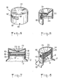
- the capsule body 1 shown in Figures 1 and 2 is cylindrical in shape and has a central groove 2 which passes diametrically through the upper plate of said capsule body and has a rectangular section. One of the ends 3 of the tray groove is closed. Given the cylindrical shape of the capsule body, the central groove has substantially the shape of a "U"
- the capsule body also has an orifice 4 to ensure the exit of the product contained in the container provided with the closure capsule.
- This orifice 4 is located in the center of the body of the capsule 1 and is advantageously provided with a sealing ring 5.
- the capsule body 1 also comprises means for fixing or hooking the cover; these means may for example be constituted by a circular groove 6 preferably located at the bottom of the capsule body.
- the capsule body 1 of the closure system according to the invention is adapted to the container to be closed; for example, it may consist of the ring of a tube 7, as shown by way of illustration in the accompanying drawings. It can also be any capsule for a glass vial or metal container, the capsule being fixed to said container whether or not in solidarity.
- the pouring spout which constitutes another element of the closure cap according to the invention is shown in FIGS. 3 and 4. It has the shape of a rectangular parallelepiped 8 of which the two ends 9 and 10 are rounded; in the remainder of this description, these ends 9 and 10 will be respectively called front 9 and rear 10 of the pouring spout.
- This parallelepiped has dimensions such that it can be housed in the groove 2 of the capsule body, the lateral faces of said parallelepiped being provided with guide means II, for example guide rods.
- the spout has in its internal part an outlet pipe 12 and 13 of the product contained in the container provided with the closure system of the invention.
- This pipe consists of two portions, one 12 passing longitudinally through the parallelepiped from the front 9 of the pouring spout to the second portion 13, which is perpendicular to it, is located towards the rear 10 of the spout and leads to the underside of said spout.
- the rear 10 of the spout is advantageously hollowed out so that it acts as a leaf spring 14.
- the pouring spout On its upper face, the pouring spout has a vertical lug 15. The relative position of the vertical lug 15 and the orifice of the portion 13 will be defined below with regard to the operation of the closure system.
- the cover 16 the third element of the closure system of the invention, is shown in Figures 5 and 6. It consists of a central plate 17 and a cylindrical skirt 18, which has a window 19 adapted to allow the outlet of the spout when in use.
- This window can be provided with a tear-away tamper-evident tab.
- the height of this window is therefore substantially greater than the height of the spout and its width preferably corresponds approximately to a quarter of the circumference of the cover.
- the skirt 18 also includes an opening 20 at its lower part; this opening 20 which is suitable for mounting the cover, must not be located below the window 19.
- the cover has in its inner part hooking means 23 constituted for example by a projection having suitable characteristics to be housed in the groove 6 of the capsule body and a stud coming closely to marry the front opening of the spout.
- the inner part of the central plate advantageously has a convex shape and comprises, in its middle, a hemispherical part 22 directed towards the inside of the cover, and, in the front part, a guide ramp 21, having a specific shape, which cooperates with the vertical lug of the pouring spout for moving it.
- front part denotes the part of the central plate which is above the skirt portion 18 where the window 19 is located.
- the guide ramp 21, integral with the central plate 17, has a specific shape adapted to allow the outlet and re-entry of the pouring spout 8 through the window 19 of the cover, by rotation of the latter, for example by rotation of a quarter of turn.
- This ramp 21 extends from the periphery of the cover towards the center of the latter and its length is a function of the width of the window.
- the shape of the ramp is defined below by its function of guiding the pouring spout, which first ensures the disengagement of the pouring spout and then the displacement thereof towards the outside when the closure system is opened. .
- This shape is such that at the start of rotation of the cover, the spout remains stationary in the central groove 2 until the front 9 of the spout is fully visible through the window 19; then, the shape of the guide ramp is suitable for allowing the outlet of the pouring spout through the window 19 until the orifice of the pipe 13 faces the orifice 4, the vertical lug 15 then being advantageously at the periphery of the cover 16.
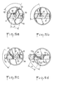
- FIG. 9 A preferred embodiment of the guide ramp 21 is shown in Figure 9 which illustrates the operation of the closure system of the invention, by rotating the cover a quarter turn.
- Figures 9a and 9d show the closure system respectively in the “closing” and “opening” positions
- Figures 9b and 9c show intermediate positions between opening and closing.
- the distance between the vertical lug 15 and the orifice of the pipe 13 and the distance between the two ends of the ramp 21 are substantially equal to the internal radius " r "of the cover 16.
- the vertical lug 15, the orifice of the pipe 13 and the side 19 ′ of the window are aligned.
- the guide ramp 21 shown in Figure 9 consists of two parts 21a and 21b.
- the part 21a of the ramp cooperates with the vertical lug 15 to keep the spout stationary until the front 9 thereof has become completely visible through the window 19 during the rotation of the cover 16.
- the shape of this part 21a is substantially that of an arc of a circle whose center is the ori fice 4 and the radius is the distance between the orifice 4 and the vertical lug 15, when the spout is entirely in the groove 2, that is to say in the closed position ( Figure 9a).
- the part 21b of the ramp cooperates with the vertical lug 15 to ensure the translational output of the pouring spout 8 from the groove 2.
- the preferred form of this part 21b shown in the figure 9 is an arc of radius "r" which passes through the center of the capsule body.
- the pouring spout 8 is positioned in the groove 2 of the capsule body; the cover 16 in the closed position is snapped onto the capsule body 1.
- the opening 20 provided on the skirt of the cover allows a mechanical finger to hold the pouring spout in the groove 2 before the cover is put in place; by removing the mechanical finger, the movable spout is trapped in the cover.
- Pressure is obtained from the movable spout on the inner wall of the cover thanks to the rear leaf spring 14. A slight clearance between the ramp and the axis allows the pressure to vary.
- the mouth of the spout is housed in the stud located in the inner side wall of the cover.
- the spout is in the use position outside the cover by unscrewing movement of a quarter of a turn of the cover. By a quarter-turn screwing movement, the spout enters the inside of the cover. The spout is driven by the rotation of the cover, the vertical lug 15 being housed in the guide rail of the cover.
- the central hemispherical part of the cover makes it possible to maintain the necessary sealing pressures during movements (opening / closing).
- the rear 10 of the spout is hollowed out and acts as a leaf spring 14; we obtain, thanks to this blade, a pressure of the movable spout on the inner wall of the cover, a slight clearance between the ramp and the lug allowing the pressure variation.
- the various elements of the closure system according to the invention can be made of the same material, for example in the case of a plastic tube, or of different materials such as, for example, a metal. It is important that the material of the spout is inert with respect to the product contained in the container. These elements are advantageously obtained by molding, injection or machining.
- the closure system allows the automatic outlet and re-entry of the spout, which are done horizontally.
- the spout substantially exceeds the outside diameter of the tube, preventing any leakage on the packaging.
- the pouring spout inside the lid is protected from any external contamination.
- the friction of the spout on the wall ensures self-cleaning thereof, thus making it possible, for example, to remove the sand in the case of containers containing solar products.
Landscapes
- Engineering & Computer Science (AREA)
- Mechanical Engineering (AREA)
- Closures For Containers (AREA)
- Thermally Insulated Containers For Foods (AREA)
- Devices For Dispensing Beverages (AREA)
- Medicinal Preparation (AREA)
Priority Applications (1)
| Application Number | Priority Date | Filing Date | Title |
|---|---|---|---|
| AT84401442T ATE23835T1 (de) | 1983-07-08 | 1984-07-06 | Verschlusskapsel mit ausschiessbarer ausgusstuelle. |
Applications Claiming Priority (2)
| Application Number | Priority Date | Filing Date | Title |
|---|---|---|---|
| FR8311456 | 1983-07-08 | ||
| FR8311456A FR2548629B1 (fr) | 1983-07-08 | 1983-07-08 | Capsule de bouchage a bec verseur auto-eclipsable |
Publications (2)
| Publication Number | Publication Date |
|---|---|
| EP0132189A1 true EP0132189A1 (de) | 1985-01-23 |
| EP0132189B1 EP0132189B1 (de) | 1986-11-26 |
Family
ID=9290677
Family Applications (1)
| Application Number | Title | Priority Date | Filing Date |
|---|---|---|---|
| EP84401442A Expired EP0132189B1 (de) | 1983-07-08 | 1984-07-06 | Verschlusskapsel mit ausschiessbarer Ausgusstülle |
Country Status (7)
| Country | Link |
|---|---|
| US (1) | US4591079A (de) |
| EP (1) | EP0132189B1 (de) |
| JP (1) | JPS60148469A (de) |
| AT (1) | ATE23835T1 (de) |
| CA (1) | CA1204082A (de) |
| DE (1) | DE3461445D1 (de) |
| FR (1) | FR2548629B1 (de) |
Cited By (5)
| Publication number | Priority date | Publication date | Assignee | Title |
|---|---|---|---|---|
| US4938393A (en) * | 1988-06-02 | 1990-07-03 | The Procter & Gamble Company | Bimodal storage and dispensing package for fluent material |
| DE4317550A1 (de) * | 1993-05-26 | 1994-12-01 | Zeller Plastik Koehn Graebner | Verschluß |
| DE4343031A1 (de) * | 1993-12-16 | 1995-06-22 | Zeller Plastik Koehn Graebner | Verschluß |
| EP0890522A1 (de) * | 1997-07-11 | 1999-01-13 | Niob Plastique | Verschlusskapsel mit einziehbarer Ausgiesstülle |
| WO2007121982A1 (de) * | 2006-04-25 | 2007-11-01 | Nestec S.A. | Kunststoff-verschluss mit schieberöffnung für einen flaschen- oder behälterstutzen |
Families Citing this family (18)
| Publication number | Priority date | Publication date | Assignee | Title |
|---|---|---|---|---|
| US4998649A (en) * | 1987-07-27 | 1991-03-12 | Thanisch Klaus J | Retractable turnspout closure |
| US5379926A (en) * | 1993-03-26 | 1995-01-10 | Aptargroup, Inc. | Dispensing closure with a twist sleeve and two internal passages |
| ITRM20070597A1 (it) * | 2007-11-16 | 2009-05-17 | Emsar Spa | Testa di erogazione per dispenser di prodotti fluidi. |
| KR101199766B1 (ko) | 2011-04-18 | 2012-11-09 | (주)연우 | 디스펜서 용기 |
| KR101265949B1 (ko) * | 2011-07-26 | 2013-05-21 | (주)연우 | 펌핑식 화장품 용기 |
| KR101265948B1 (ko) * | 2011-07-26 | 2013-05-21 | (주)연우 | 펌핑식 화장품 용기 |
| WO2018139977A1 (en) | 2017-01-26 | 2018-08-02 | Şahsan Maki̇na Kalip Elektri̇k Ve Elektroni̇k Sanayi̇ Ve Ti̇caret Li̇mi̇ted Şi̇rketi̇ | A container lid structure |
| US10597204B2 (en) | 2018-02-20 | 2020-03-24 | Navajo Manufacturing Company, Inc. | Travel bottle with slide lock |
| USD856804S1 (en) | 2018-02-20 | 2019-08-20 | Navajo Manufacturing Company, Inc. | Travel bottle cap with slide lock |
| USD854415S1 (en) | 2018-02-20 | 2019-07-23 | Navajo Manufacturing Company, Inc. | Travel bottle cap with twisting locking lid |
| US10167120B1 (en) * | 2018-02-20 | 2019-01-01 | Navajo Manufacturing Company, Inc. | Travel bottle with twisting locking lid |
| US10745179B2 (en) | 2018-02-20 | 2020-08-18 | Navajo Manufacturing Company, Inc. | Travel bottle with slide or rotatable lock |
| US10604309B2 (en) | 2018-06-19 | 2020-03-31 | Navajo Manufacturing Company, Inc. | Travel bottle with slide lock |
| USD867138S1 (en) | 2018-09-06 | 2019-11-19 | Navajo Manufacturing Company, Inc. | Travel bottle cap with slide lock |
| USD867140S1 (en) | 2018-09-06 | 2019-11-19 | Navajo Manufacturing Company, Inc. | Travel bottle cap |
| USD867139S1 (en) | 2018-09-06 | 2019-11-19 | Navajo Manufacturing Company, Inc. | Travel bottle cap with rotatable lock |
| US10988291B2 (en) | 2019-05-16 | 2021-04-27 | Navajo Manufacturing Company, Inc. | Travel bottle having a twisting locking ring body |
| USD902716S1 (en) | 2019-05-16 | 2020-11-24 | Navajo Manufacturing Company, Inc. | Travel bottle cap having a twisting locking ring body |
Citations (2)
| Publication number | Priority date | Publication date | Assignee | Title |
|---|---|---|---|---|
| GB2088838A (en) * | 1980-10-28 | 1982-06-16 | Drdlik Frank | Closures for Containers |
| GB2112761A (en) * | 1982-01-08 | 1983-07-27 | Dusan Sava Lajovic | Closure with transversely movable nozzle |
Family Cites Families (1)
| Publication number | Priority date | Publication date | Assignee | Title |
|---|---|---|---|---|
| US3847313A (en) * | 1973-02-16 | 1974-11-12 | Leeds & Micallef | Retractable turnspout closure |
-
1983
- 1983-07-08 FR FR8311456A patent/FR2548629B1/fr not_active Expired
-
1984
- 1984-07-06 CA CA000458306A patent/CA1204082A/en not_active Expired
- 1984-07-06 US US06/628,560 patent/US4591079A/en not_active Expired - Fee Related
- 1984-07-06 AT AT84401442T patent/ATE23835T1/de not_active IP Right Cessation
- 1984-07-06 DE DE8484401442T patent/DE3461445D1/de not_active Expired
- 1984-07-06 EP EP84401442A patent/EP0132189B1/de not_active Expired
- 1984-07-09 JP JP59140752A patent/JPS60148469A/ja active Pending
Patent Citations (2)
| Publication number | Priority date | Publication date | Assignee | Title |
|---|---|---|---|---|
| GB2088838A (en) * | 1980-10-28 | 1982-06-16 | Drdlik Frank | Closures for Containers |
| GB2112761A (en) * | 1982-01-08 | 1983-07-27 | Dusan Sava Lajovic | Closure with transversely movable nozzle |
Cited By (7)
| Publication number | Priority date | Publication date | Assignee | Title |
|---|---|---|---|---|
| US4938393A (en) * | 1988-06-02 | 1990-07-03 | The Procter & Gamble Company | Bimodal storage and dispensing package for fluent material |
| DE4317550A1 (de) * | 1993-05-26 | 1994-12-01 | Zeller Plastik Koehn Graebner | Verschluß |
| DE4343031A1 (de) * | 1993-12-16 | 1995-06-22 | Zeller Plastik Koehn Graebner | Verschluß |
| EP0890522A1 (de) * | 1997-07-11 | 1999-01-13 | Niob Plastique | Verschlusskapsel mit einziehbarer Ausgiesstülle |
| FR2765860A1 (fr) * | 1997-07-11 | 1999-01-15 | Niob Plastique | Capsule de bouchage a bec verseur auto-eclipsable |
| WO2007121982A1 (de) * | 2006-04-25 | 2007-11-01 | Nestec S.A. | Kunststoff-verschluss mit schieberöffnung für einen flaschen- oder behälterstutzen |
| US8251240B2 (en) | 2006-04-25 | 2012-08-28 | Nestec S.A. | Plastic closure comprising a slide opening for a bottle neck or container neck |
Also Published As
| Publication number | Publication date |
|---|---|
| ATE23835T1 (de) | 1986-12-15 |
| FR2548629A1 (fr) | 1985-01-11 |
| DE3461445D1 (en) | 1987-01-15 |
| JPS60148469A (ja) | 1985-08-05 |
| US4591079A (en) | 1986-05-27 |
| EP0132189B1 (de) | 1986-11-26 |
| FR2548629B1 (fr) | 1985-12-06 |
| CA1204082A (en) | 1986-05-06 |
Similar Documents
| Publication | Publication Date | Title |
|---|---|---|
| EP0132189B1 (de) | Verschlusskapsel mit ausschiessbarer Ausgusstülle | |
| EP0342109B1 (de) | Verschlusseinrichtung mit drehbarer Manschette für Flakons und ähnliche Behälter | |
| EP0452196B1 (de) | Abgabevorrichtung für wenigstens ein flüssiges oder cremeartiges Produkt | |
| EP0538094B1 (de) | Metallbehälter, der entlang einer Schwächungslinie teilweise geöffnet werden kann | |
| CA1057245A (fr) | Dispositif de conditionnement de deux produits isoles l'un de l'autre avant la distribution | |
| EP0410858B1 (de) | Abgabevorrichtung für wenigstens ein flüssiges Produkt, insbesondere kosmetischer oder pharmazeutischer Art | |
| EP0406397B1 (de) | Dichtungsstopfen mit hochziehbarem, in verschiedene richtungen einstellbarem ausgussrohr | |
| EP0694483A1 (de) | Behälter zur Aufnahme von mindestens zwei Produkten, zur deren Mischung sowie zur Abgabe dieser Mischung | |
| EP1044893A1 (de) | Vorrichtung zum unmittelbaren Vermischen von mindestens zwei Produkten, von denen eines ein Pulver ist | |
| EP1084060B1 (de) | Verschluss mit perforiermitteln und ausgiesseinheit | |
| EP0528707A1 (de) | Zwei-Flaschen-Verpackung zur getrennten Aufbewahrung von zwei Produkten, insbesondere flüssigen und zur Mischung derselben vor dem Gebrauch | |
| EP0475789A1 (de) | Vorrichtung zur getrennten Aufbewahrung wenigstens zweier Produkte und zum Mischen derselben beim ersten Gebrauch | |
| FR2738550A1 (fr) | Dispositif d'obturation d'un recipient lui-meme ferme, ensemble pour dispenser un produit comprenant un tel recipient et un tel dispositif d'obturation | |
| FR2760725A1 (fr) | Dispositif distributeur pour produits fluides | |
| EP3199245A1 (de) | Entlüftungsvorrichtung für dispenser eines flüssigprodukts ohne nachsaugen von luft | |
| EP0890522A1 (de) | Verschlusskapsel mit einziehbarer Ausgiesstülle | |
| CA2186396C (fr) | Dispositif de conditionnement et de distribution | |
| WO1999000308A1 (fr) | Ensemble verseur a bouchage a vis pour un recipient | |
| FR2687640A1 (fr) | Dispositif pour conserver separes l'un de l'autre au moins deux produits et pour effectuer leur melange ulterieurement, notamment au moment de l'utilisation. | |
| FR2750954A1 (fr) | Bouchon en matiere synthetique destine a distribuer un liquide contenu dans un recipient, notamment une boisson | |
| EP0373989B1 (de) | Behälterverschlusskappe mit schwenkbarem Betätigungselement zum Abgeben des Behälterinhalts | |
| EP0648683A1 (de) | Verschlussvorrichtung für einen mit einem Hals versehenen flaschen- oder topfförmigen Behälter | |
| EP0739826B1 (de) | Verschlussvorrichtung mit einer seitlichen, axial ausziehbaren Oeffnung | |
| FR2584855A1 (fr) | Conteneur pour dechets radioactifs de moyenne ou faible activite | |
| FR2674508A1 (fr) | Bouchon verseur-reducteur pour liquides. |
Legal Events
| Date | Code | Title | Description |
|---|---|---|---|
| PUAI | Public reference made under article 153(3) epc to a published international application that has entered the european phase |
Free format text: ORIGINAL CODE: 0009012 |
|
| AK | Designated contracting states |
Designated state(s): AT BE CH DE FR GB IT LI LU NL SE |
|
| 17P | Request for examination filed |
Effective date: 19850702 |
|
| 17Q | First examination report despatched |
Effective date: 19860210 |
|
| GRAA | (expected) grant |
Free format text: ORIGINAL CODE: 0009210 |
|
| AK | Designated contracting states |
Kind code of ref document: B1 Designated state(s): AT BE CH DE FR GB IT LI LU NL SE |
|
| REF | Corresponds to: |
Ref document number: 23835 Country of ref document: AT Date of ref document: 19861215 Kind code of ref document: T |
|
| ITF | It: translation for a ep patent filed | ||
| REF | Corresponds to: |
Ref document number: 3461445 Country of ref document: DE Date of ref document: 19870115 |
|
| PLBE | No opposition filed within time limit |
Free format text: ORIGINAL CODE: 0009261 |
|
| STAA | Information on the status of an ep patent application or granted ep patent |
Free format text: STATUS: NO OPPOSITION FILED WITHIN TIME LIMIT |
|
| 26N | No opposition filed | ||
| REG | Reference to a national code |
Ref country code: GB Ref legal event code: 746 |
|
| PGFP | Annual fee paid to national office [announced via postgrant information from national office to epo] |
Ref country code: GB Payment date: 19910628 Year of fee payment: 8 |
|
| PGFP | Annual fee paid to national office [announced via postgrant information from national office to epo] |
Ref country code: AT Payment date: 19910702 Year of fee payment: 8 |
|
| PGFP | Annual fee paid to national office [announced via postgrant information from national office to epo] |
Ref country code: CH Payment date: 19910708 Year of fee payment: 8 |
|
| PGFP | Annual fee paid to national office [announced via postgrant information from national office to epo] |
Ref country code: LU Payment date: 19910717 Year of fee payment: 8 |
|
| PGFP | Annual fee paid to national office [announced via postgrant information from national office to epo] |
Ref country code: DE Payment date: 19910722 Year of fee payment: 8 |
|
| PGFP | Annual fee paid to national office [announced via postgrant information from national office to epo] |
Ref country code: SE Payment date: 19910723 Year of fee payment: 8 |
|
| PGFP | Annual fee paid to national office [announced via postgrant information from national office to epo] |
Ref country code: FR Payment date: 19910730 Year of fee payment: 8 |
|
| ITTA | It: last paid annual fee | ||
| PGFP | Annual fee paid to national office [announced via postgrant information from national office to epo] |
Ref country code: NL Payment date: 19910731 Year of fee payment: 8 |
|
| PGFP | Annual fee paid to national office [announced via postgrant information from national office to epo] |
Ref country code: BE Payment date: 19910809 Year of fee payment: 8 |
|
| EPTA | Lu: last paid annual fee | ||
| PG25 | Lapsed in a contracting state [announced via postgrant information from national office to epo] |
Ref country code: LU Free format text: LAPSE BECAUSE OF NON-PAYMENT OF DUE FEES Effective date: 19920706 Ref country code: GB Effective date: 19920706 Ref country code: AT Effective date: 19920706 |
|
| PG25 | Lapsed in a contracting state [announced via postgrant information from national office to epo] |
Ref country code: SE Effective date: 19920707 |
|
| PG25 | Lapsed in a contracting state [announced via postgrant information from national office to epo] |
Ref country code: LI Effective date: 19920731 Ref country code: CH Effective date: 19920731 Ref country code: BE Effective date: 19920731 |
|
| BERE | Be: lapsed |
Owner name: BIGOTTE GEORGES Effective date: 19920731 |
|
| PG25 | Lapsed in a contracting state [announced via postgrant information from national office to epo] |
Ref country code: NL Effective date: 19930201 |
|
| GBPC | Gb: european patent ceased through non-payment of renewal fee |
Effective date: 19920706 |
|
| NLV4 | Nl: lapsed or anulled due to non-payment of the annual fee | ||
| PG25 | Lapsed in a contracting state [announced via postgrant information from national office to epo] |
Ref country code: FR Effective date: 19930331 |
|
| REG | Reference to a national code |
Ref country code: CH Ref legal event code: PL |
|
| PG25 | Lapsed in a contracting state [announced via postgrant information from national office to epo] |
Ref country code: DE Effective date: 19930401 |
|
| REG | Reference to a national code |
Ref country code: FR Ref legal event code: ST |
|
| EUG | Se: european patent has lapsed |
Ref document number: 84401442.3 Effective date: 19930204 |