EP0133025A1 - Gerät zur Aufzeichnung und/oder Wiedergabe von Bandkassetten - Google Patents
Gerät zur Aufzeichnung und/oder Wiedergabe von Bandkassetten Download PDFInfo
- Publication number
- EP0133025A1 EP0133025A1 EP84305090A EP84305090A EP0133025A1 EP 0133025 A1 EP0133025 A1 EP 0133025A1 EP 84305090 A EP84305090 A EP 84305090A EP 84305090 A EP84305090 A EP 84305090A EP 0133025 A1 EP0133025 A1 EP 0133025A1
- Authority
- EP
- European Patent Office
- Prior art keywords
- arm member
- arm
- chassis
- cassette
- axis
- Prior art date
- Legal status (The legal status is an assumption and is not a legal conclusion. Google has not performed a legal analysis and makes no representation as to the accuracy of the status listed.)
- Granted
Links
Images





Classifications
-
- G—PHYSICS
- G11—INFORMATION STORAGE
- G11B—INFORMATION STORAGE BASED ON RELATIVE MOVEMENT BETWEEN RECORD CARRIER AND TRANSDUCER
- G11B5/00—Recording by magnetisation or demagnetisation of a record carrier; Reproducing by magnetic means; Record carriers therefor
- G11B5/48—Disposition or mounting of heads or head supports relative to record carriers ; arrangements of heads, e.g. for scanning the record carrier to increase the relative speed
- G11B5/54—Disposition or mounting of heads or head supports relative to record carriers ; arrangements of heads, e.g. for scanning the record carrier to increase the relative speed with provision for moving the head into or out of its operative position or across tracks
-
- G—PHYSICS
- G11—INFORMATION STORAGE
- G11B—INFORMATION STORAGE BASED ON RELATIVE MOVEMENT BETWEEN RECORD CARRIER AND TRANSDUCER
- G11B15/00—Driving, starting or stopping record carriers of filamentary or web form; Driving both such record carriers and heads; Guiding such record carriers or containers therefor; Control thereof; Control of operating function
- G11B15/18—Driving; Starting; Stopping; Arrangements for control or regulation thereof
- G11B15/1883—Driving; Starting; Stopping; Arrangements for control or regulation thereof for record carriers inside containers
-
- G—PHYSICS
- G11—INFORMATION STORAGE
- G11B—INFORMATION STORAGE BASED ON RELATIVE MOVEMENT BETWEEN RECORD CARRIER AND TRANSDUCER
- G11B5/00—Recording by magnetisation or demagnetisation of a record carrier; Reproducing by magnetic means; Record carriers therefor
- G11B5/48—Disposition or mounting of heads or head supports relative to record carriers ; arrangements of heads, e.g. for scanning the record carrier to increase the relative speed
- G11B5/56—Disposition or mounting of heads or head supports relative to record carriers ; arrangements of heads, e.g. for scanning the record carrier to increase the relative speed with provision for moving the head support for the purpose of adjusting the position of the head relative to the record carrier, e.g. manual adjustment for azimuth correction or track centering
Definitions
- This invention relates to cassette tape recording and/or reproducing apparatus.
- the invention is particularly concerned with the so-called head base assembly of such apparatus, that is, the structure by which the magnetic head or heads and the pinch roller are movably supported in such apparatus.
- the head base plate which carries a recording and reproducing head and an erasing head is mounted on the chassis for rectilinear movements between operative and inoperative positions.
- the head base plate is usually pivotally mounted on the chassis for minimizing the space required therefor.
- one end of the head base plate may be pivotally mounted on a pivot post extending perpendicularly from a chassis, and a recording and reproducing head and an erasing head are mounted on the head. base plate at positions thereon remote from the pivot post so as to be movable between inoperative and operative positions in response to corresponding pivotal movements of the head base plate.
- the end portion of the head base plate remote from the pivot post is susceptible to undesirable vibration or small movements in the direction normal to the plane of the chassis on which the cassette is located. If such vibrations or small movements occur in the recording or reproducing mode of the apparatus, the recording and reproducing head and the erasing head do not precisely engage the desired track or tracks on the magnetic tape.
- the head base plate is usually of one-piece construction and has both a pinch roller and at least one magnetic head mounted thereon at relatively smaller and larger distances, respectively, from the pivot post.
- the angular movements of the head base plate between its operative and inoperative positions must be large enough so that, in the inoperative position, the pinch roller will be withdrawn from a tape cassette located on the chassis to permit the loading or ejecting of the tape cassette.
- the magnetic head is at a further distance form the pivot post than the pinch roller on the one-piece head base plate, the angular movement of the head base plate to its inoperative position will result in an undesirably large movement of the magnetic head away from the tape cassette with the result that such arrangement is wasteful of space.
- a cassette tape recording and/or reproducing apparatus comprising:
- a cassette tape recording and/or reproducing apparatus having a chassis defining a substantially flat plane on which a tape cassette is arranged to be located, and a magnetic head movable into a cassette located on the chassis for engaging a driven tape therein and recording or reproducing signals on such tape; a head base assembly which comprises a first arm member mounted, at one end, on the chassis for swinging about a first axis perpendicular to the plane on which the cassette is located, a second arm member having the magnetic head fixed thereto and being connected in end-to-end relation to the other end of the first arm member by joint means permitting relative angular displacements of the arm members about a second axis parallel to the first axis, and a fixed guide post extending parallel to the plane of the chassis and passing slidably through a slot in one of the arm members, and preferably in the second arm member, for stabilizing the distance from the magnetic head to the plane on which the cassette is located as the magnetic head moves into and out of a cassette
- the joint means connecting the first and second arm members includes a screw member defining the second axis and being turnable relatively to displace the connected ends of the arm members in the direction along the second axis for rocking the second arm member about the guide post member and thereby adjusting the azimuth of the magnetic head fixed to the second arm member.
- a portable cassette tape reproducing apparatus 1 is intended to accommodate a standard tape cassette 2 containing a pair of rotatable reel hubs 3a and 3b.
- a magnetic tape 4 has its ends fixed to the hubs 3a and 3b, and is wound on the latter, with the portion of the tape 4 extending between the hubs 3a and 3b being guided by rollers 5a and 5b so as to run in a path extending along a front peripheral wall 2a of the cassette 2.
- the front peripheral wall 2a has a central opening or window 6a and a pair of windows 6b at opposite sides of the central window 6a.
- a pressure pad 7 is mounted within the cassette 2 so as to confront the central window 6a.
- the cassette 2 has pairs of holes 8a and 8b in the top and bottom walls of the cassette 2 adjacent to the front peripheral wall 2a at locations intermediate the central window 6a and the windows 6b. Finally, the top and bottom walls of the cassette 2 are shown to have pairs of holes 8'a and 8'b spaced outwardly from the holes 8a and 8b, respectively, so as to be positioned adjacent to the windows 6b.
- the portable cassette tape reproducing apparatus 1 is generally shown to comprise a chassis 9 defining a flat plane on which the cassette 2 is to be located with the front peripheral wall 2a of the cassette 2 abutting against an upstanding wall 9a at the forward portion of the chassis 9.
- a rotary capstan 10 extends upwardly from the chassis 9 into one or the other of the pairs of holes 8'a and 8'b of the cassette 2 located on the chassis 9.
- a pair of spaced-apart spindles or drive shafts lla or 11b extend upwardly from the chassis 9 and are arranged to engage and be rotatably coupled with the hubs 3a and 3b of the located cassette 2.
- Positioning pins 12a and 12b extend upwardly from the chassis 9 and are arranged to be received in the holes 8a and 8b for accurately positioning the cassette 2 on the chassis 9.
- a spring 13 is provided on the chassis 9 to engage the back peripheral wall 2b of the cassette 2 at the centre for yieldably urging the cassette 2 forward and thereby ensuring firm contact of the front peripheral wall 2a of the cassette 2 with the upstanding wall 9a of the chassis 9.
- the apparatus 1 is further shown to have a magnetic head 15 and a pinch roller 16 carried by a head base assembly 17, and which is disposed in front of the upstanding wall 9a, that is, at the side 9'a of the wall 9a which is opposite to the side engaged by the cassette 2.
- a push-button device 18 extends from a front wall la of the apparatus 1 and is manually actuable for effecting movements of the head base assembly 17 from an inoperative position shown in full lines in Figure 4 to an operative position shown in dot-dash lines.
- the upstanding wall 9a of the chassis 9 is shown to have apertures 19a and ,L9b which register with the windows 6a and 6b of the cassette 2 located on the chassis 9 so that, when the push-button device 18 is actuated, the magnetic head 15 and the pinch roller 16 are moved through the aperture 19a and the window 6a, and through the aperture 19b and one of the windows 6b, respectively, and press the tape 4 against the pressure pad 7 and the capstan 10, respectively, as shown in dot-dash lines in Figure 1.
- a tape guide 20 fixedly mounted beside the magnetic head 15 is moved with the magnetic head 15 through the aperture 19a and the window 6a for engaging, and thereby guiding the opposite longitudinal edges of the tape 4.
- the capstan 10 and the shafts 11a and llb are suitably driven by a motor (not shown) so that the tape 4 is propelled at a constant speed between the magnetic head 15 and the pressure pad 7, thereby to establish the reproducing or playback mode of the apparatus 1.
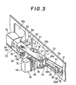
- the head base assembly 17 generally comprises a first arm member 22 mounted, at one end, on the chassis 9 for swinging relative to the chassis 9 about a first axis perpendicular to the plane on which the cassette 2 is located, a second arm member 23 having the magnetic head 15 mounted thereon, and a joint structure 24 connecting the second arm member 23 in end-to-end relation to the other end of the first arm member 22, and permitting relative angular displacements of the arm members 22 and 23 about a second axis parallel to the first axis.
- the first arm member 22 is preferably formed of sheet metal and, at one end portion 22a, has a rearwardly bent end 22d.
- Parallel, forwardly directed upper and lower flanges 25a and 25b extend along the first arm member 22 from a central portion 22b thereof to the end 22c remote from the bent end 22d.
- An elongated slot 26 extends along the first arm member 22 from the central portion 22b to the bent end 22d.
- a window or cut-out 27 is formed in the first arm member 22 between the flanges 25a and 25b along the length of the first arm member 22 between the central portion 22b and the end 22c.
- the second arm member 23 preferably includes an elongated metal plate 23a on which the magnetic head 15 is suitably secured, as by welding, and an attachment portion 29 moulded or otherwise suitably formed of a synthetic resin and being secured, as by a screw 30, to a projecting end portion 23b of the plate 23a.
- the attachment portion 29 is formed with a depending projection 28a which is receivable in a hole 28b formed in the end portion 23b of the plate 23a so as to cooperate with the screw 30 in securely positioning the plate 23a and the attachment portion 29 relative to each other.
- the bent end 22d of the first arm member 22 is inserted into a slit 31 extending through the upstanding wall 9a at right angles to the plane of the chassis 9 on which the cassette 2 is to be located.
- the first arm member 22 is mounted with respect to the upstanding wall 9a of the chassis 9 for swinging movemenets relative thereto in the directions of the arrows a and b in Figure 4 about a first axis defined by the slit 31.
- the joint structure 24 is shown to include a screw member 32 secured to the first arm member 22 adjacent to the end 22c of the first arm member 22 remote from the bent end 22d and extending parallel to the axis defined by the slit 31 for defining the second axis about which the second arm member 23 is swingable relative to the first arm member 22 in the directions of the arrows c and d in Figure 4.
- the first arm member 22 is urged in the direction of the arrow b to its inoperative position shown in full lines in Figure 4 by a bowed leaf spring 33 which is positioned between the arm member 22 and the upstanding wall 9a.
- the leaf spring 33 has a hole 34 extending therethrough relatively close to one end so as to divide the length of the leaf spring 33 into a short portion 33a which is formed with a central notch 35 at a forked end 33a', and a relatively long portion 33b.
- a screw 36 extends through the hole 34 in the leaf spring 33 and is screwed into a tapped hole 37 in the upstanding wall 9a for securing the leaf spring 33 to the upstanding wall 9a, and terminating in an end 33b' which acts against the central portion 22b of the first arm member 22.
- a claw 38 is formed at the end of the slot 26 terminating in the bent end 22d of the first arm member 22, and the short portion 33a of the leaf spring 33 is dimensioned so that the claw 38 is received in the notch 35.
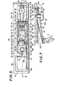
- the forked end 33a' of the leaf spring 33 acts against the bent end 22d for urging the bent end 22d in the direction of the arrow b' in Figure 7.
- the leaf spring 33 acts to ensure engagement of the bent end 22d of the first arm member 22 in the slit 31 of the upstanding wall 9a. It will be appreciated that, when the first arm member 22 is moved in the direction of the arrow a to its operative position shown in dot-dash lines in Figure 7, the major portion of the length of the leaf spring 33 is received in the slot 26.
- the second arm member 23 is urged to turn relative to the first arm member 22 in the direction of the arrow c in Figure 4 by means of a coil spring 39 extending around the screw member 32 and engaging, at its opposite ends, against the arm members 22 and 23, as hereinafter described in detail.
- the attachment portion 29 of the second arm member 23 is engageable against the end 22c of the first arm member 22 for limiting the turning of the second arm member 23 relative to the first arm member 22 under the urging of the coil spring 39 to the relative positions shown in solid lines in Figure 4 and in which a predetermined angle 8 is included between the longitudinal axes of the arm members 22 and 23.
- a support arm 41 for the pinch roller 16 is shown particularly in Figure 2 to be formed of sheet metal and to have parallel flange portions 41a and 41b with a connecting portion 41c extending therebetween.
- the pinch roller 16 is shown to be rotatable on an axle 42 which, at its opposite ends, is mounted in end portions of the flanges 41a and 41b extending beyond the connecting portion 41c.
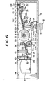
- the pinch roller support arm 41 is pivotally mounted, at its end remote from the axle 42, on a pivot pin 43 ( Figures 3 to 6) which is secured, at its ends, in the flanges 25a and 25b of the first arm member 22 adjacent to the central portion 22b of the first arm member 22.
- the support arm 41 is angularly urged relative to the first arm member 22 in the direction of the arrow e in Figure 4, that is, in the direction urging the pinch roller 16 to extend through the cut-out 27 of the first arm member 22, by means of a coiled spring member 44 which is mounted on the pivot pin 43 between the flanges 41a and 41b.
- the angular displacement of the pinch roller support arm 41 relative to the first arm member 22 under the urging of the spring member 44, that is, in the direction of the arrow e in Figure 4, is limited by the engagement of a downwardly projecting lower end portion 42a of the axle 42 with a stop 45 ( Figures 2, 5 and 6) extending from the flange 25b into the cut-out 27 of the first arm member 22.
- the coiled spring member 44 is particularly shown in Figure 2 to have a pair of parallel end portions 44a and 44b extending from a pair of coil portions 44c and 44d, respectively, and a U-shaped central portion 44e extending between the coil portions 44c and 44d and initially formed to lie in a plane approximately at right angles to the plane of the end portions 44a and 44b.
- the coil portions 44c and 44d extend around the pivot pin 43 ( Figures 3 to 6) with the end portions 44a and 44b engaging in notches 46a and 46b formed in the top and bottom edges of the first arm member 22, and with the central portion 44e engaging resiliently against the connecting portion 41c of the pinch roller support arm 41 so as to urge the pinch roller support arm 41 in the direction of the arrow e in Figure 4.
- the spring member 44 is dimensioned so that, when installed as described above, the coil portions 44c and 44d are resiliently urged in the opposite axial directions against the flange portions 41a and 41b of the pinch roller support arm 41 with the result that the central portion 44e of the spring member 44 is precisely centred with respect to the central plane P of the pinch roller 16, as shown in Figure 5. If the material of the spring member 44 has a small "resilient constant", sufficient pressure will be obtained from the two coil portions 44c and 44d. As shown particularly in Figures 2 and 5, the connecting portion 41c of the pinch roller support arm 41 has a hole 47 therein, and the U-shaped central portion 44e of the spring member 44 is dimensioned to extend around the hole 47.
- the push-button device 18 includes a slide 48 mounted below the chassis 9 for slidable movements relative thereto in the directions of the arrows g and h in Figure 4.
- a body portion 49 of the push-button device 18 projects forwardly through a corresponding opening in the front wall la of the apparatus 1 and is preferably moulded of a synthetic resin so as to have a rim 49a which prevents forward removal of the body portion 49 through the respective opening in the front wall la.
- Laterally spaced-apart stiffening ribs 52 are formed integrally on the back surface of the body portion 49 along with a bottom portion 53 extending rearwardly from the body portion 49 between the lower ends of the ribs 52.
- the actuator portion 50 includes a pair of upstanding resilient posts 50a extending from the opposite sides of the bottom portion 53 at the end remote from the body portion 49 and being connected, at their upper ends, by an integral lateral beam 50b.
- a spring locating projection 54 extends from the centre of the beam 50b in the direction towards the body portion 49 and is inserted in the coil spring 51 for locating the coil spring 51.
- a wedge-shaped projection 55 extends from the centre of the beam 50b in the direction away from the body portion 49.
- a screw 56 extends through a hole in the bottom portion 53 and secures it to the slide 48.
- the slide 48 and the push-button device 18 connected therewith are located with respect to the head base assembly 17 so that the wedge-shaped projection 55 extends through the hole 47 in the pinch roller support arm 41 and engages, at its free end, against the central portion 22b of the first arm member 22.
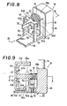
- the coil spring 51 can be replaced by rubber or other resilient members, for example, by an elongated plate spring 59 fixed, at one end, by the screw 56 to the bottom portion 53, while the other or free end of the plate spring 59 acts against the surface of the beam 50b, as shown in Figure 11.
- a resilient element functionally equivalent to the plate spring 59 of Figure 11 could be formed integrally with the body portion 49 of the push-button device 18.
- the slide 48 is moved by a spring (not shown) in the direction of the arrow h in Figure.4 for disposing the body portion 49 of the push-button device 18 in its operative position shown in full lines.
- the leaf spring 33 urges the first arm member 22 angularly in the direction of the arrow b about the axis defined by the bent end 22d engaging in the slit 31, with the result that the magnetic head 15 and the pinch roller 16 are maintained in their inoperative positions shown in full lines.
- the first arm member 22 is angularly displaced in the direction of the arrow a in Figure 4 to its operative position shown in dot-dash lines in response to movement of the body portion 49 towards its operative position.
- the first arm member 23 In response to such angular displacement of the first arm member 22, the first arm member 23 is similarly moved to its operative position shown in dot-dash lines in Figure 4 with the result that the magnetic head 15 and the pinch roller 16 are moved to their respective operative positions bearing against the pressure pad 7 and the capstan 10 with the tape 4 therebetween.
- the several parts of the head base assembly 17 are dimensioned so that prior to the arrival of the first arm member 22 at its operative position shown in broken lines in Figure 4, the pinch roller 16 comes against the capstan 10 with the result that, during the final angular displacement of the first arm member 22 to its operative position, the pinch roller support arm 41 turns slightly relative to the first arm member 22 in the direction of the arrow f about the pivot 43. Such turning of the pinch roller support arm 41 in the direction of the arrow f relative to the first arm member 22 is effected against the force of the spring member 44.
- the pressure of the pinch roller 16 against the capstan 10 in the operative position of the pinch roller 16 is established by the spring member 44 with such pressure being uniformly applied by reason of the precise positioning of the central portion 44e of the spring member 44 relative to the central plane of the pinch roller 16, as previously described.
- the posts 50a and the coil spring 51 can flex to permit the final additional movement of the body portion 49 and the slide 48 to their operative positions at which the slide 48 is thereafter locked. Thereafter, and so long as the push-button device 18 is locked in its operative position, the first arm member 22 continues to be pressed against the side 9a' of the upstanding wall 9a by the resilient forces of the posts 50a of the actuator portion 50 and the coil spring 51, respectively.
- a stop surface 60 formed on the attachment portion 29 of the second arm member 23 engages against the side 9a'.
- the orientation of the magnetic head 15 is maintained parallel to the run of the tape 4 exposed at the window 6a for ensuring that the gap in the magnetic core of the magnetic head 15 precisely scans the tape 4. Because the second arm member 23 is pressed against the front side 9a' of the upstanding wall 9a by the force of the coil spring 39, the magnetic head 15 is precisely and reliably located in its operative position. Further, by suitably locating the stop surface 60 on the attachment portion 29 of the second arm member 23, the frictional resistance to the movement of the tape 4 between the pressure pad 7 and the operatively positioned magnetic head 15 can be easily maintained constant at a preferred value, so that the magnetic tape path is stabilized during recording and/or reproducing operations.
- the distance L l between the location P2 where the head base assembly 17 is pivoted on the chassis 9, and the location P 3 where the magnetic head 15 is engageable against the tape 4 backed up by the pressure pad 7 can be made relatively small while the magnetic head 15 is maintained in an orientation parallel to the run of the tape 4 extending between the rollers 5a and 5b in the operatively positioned cassette 2.
- the stroke S 2 ( Figure 4) of the magnetic head 15 between its inoperative and operative positions can be made smaller than, or at least no greater than the stroke S 1 of the first arm member 22 at its end 22c.
- the wedge-shaped projection 55 of the push-button device 18 acts directly against the first arm member 22 at a location P4 ( Figure 4) near to the pinch roller 16 and at a distance L 2 from the location P 2 which is preferably approximately one-third the distance L 19 the stroke S 3 for the body portion 49 of the push-button device 18 can be substantially shorter than the stroke S 2 of the magnetic head 15.
- the projection of the push-button device 18 from the front wall la of the housing of the apparatus 1 can be minimized.
- the head base assembly 17 further includes a pair of parallel guide posts 62 and 63 extending fixedly from the front side 9a' of the upstanding wall 9a parallel to the plane of the chassis 9 on which the cassette 2 is located.
- the guide posts 62 and 63 are slidably received in slots 64 and 65, respectively, formed in the end portion 22c of the first arm member 22 and in an end portion 29a of the attachment portion 29 of the second arm member 23, respectively.
- the slot 64 has a width W 1 which is approximately equal to the diameter D 1 of the post 62
- the slot 65 has a width W 2 approximately equal to the diameter D 2 of the post 63.
- the fixed posts 62 and 63 stablize the distances from the engaged portions of the arm members 22 and 23 to the plane of the chassis 9 on which the cassette 2 is located during the angular displacements of the arm members 22 and 23 for moving the magnetic head 15 to and from its operative position.
- the post 62 is shown to have a head 62a at the end thereof remote from the upstanding wall 9a and which is engageable by the end 22c of the first arm member 22 for defining the inoperative position of the first arm member 22 to which it is urged by the leaf spring 33.
- the slot 64 is shown, particularly in Figure 13, to have an enlarged diameter end portion 66 through which the head 62a of the post 62 can be inserted when the first arm member 22 is being mounted for pivotal movements relative to the upstanding wall 9a.
- the screw member 32 of the joint structure 24 is shown to have a smooth portion or shaft 68 terminating in a threaded lower end portion 69, and an enlarged head 71 at its other end formed with a slot 70 for receiving a screwdriver, and defining a shoulder 72 between the head 71 and the shaft 68 ( Figure 14).
- the upper flange 25a of the first arm member 22 has arcuate rims 73 depending therefrom at opposite sides of a slot 75 and being dimensioned slidably to embrace the head 71 of the screw member 32 ( Figure 15).
- the threaded lower end portion 69 of the screw member 32 is threadably engaged in a tapped hole 74 in the lower flange 25b in the first arm member 22.
- the end portion 29b of the attachment portion 29 remote from the end portion 29a is in the form of a cylindrical hub 76 defining a frusto- conical cavity 77 loosely receiving the screw member 32 and providing, at its upper end, a seat for the shoulder 72 of the screw member ( Figure 14).
- the coil spring 39 is disposed around the screw member 32 between the lower flange 25b of the first arm member 22 and the hub 76 so that the upper surface or seat defined by the hub 76 is urged by the coil spring 39 against the shoulder 72 of the screw member 32.
- the attachment portion 29 has a depression or cut-out 79 between its end portions 29a and 29b for accommodating the guide post 62 so that the guide post 62 will not interfere with either angular movements of the second arm member 23 relative to the first arm member 22 about the axis of the screw member 32 or with rocking movements of the second arm member 23 about the axis of the guide post 63.
- the guide post 63 performs dual functions, that is, It functions to hold the second arm member 23 at a constant height relative to the chassis 9 during the movements of the magnetic head 15 between its operative and inoperative positions, and it also functions as the axis about which the second arm member 23 rocks when the screw member 32 is turned in one direction or the other for adjusting the azimuth angle of the magnetic head 15.
- the coil spring 39 also has dual functions, namely, angularly to urge the second arm member 23 in one direction relative to the first arm member 22 about the axis of the screw member 32, and to urge the hub 76 along the screw member 32 in the direction for heating the hub 76 against the head 71 of the screw member 32. From the froregoing, it will be appreciated that the head base assembly 17 has several of its parts constructed and arranged relative to each other to perform dual functions, thereby simplifying the structure and minimizes the space required therefor.
Landscapes
- Adjustment Of The Magnetic Head Position Track Following On Tapes (AREA)
- Automatic Tape Cassette Changers (AREA)
- Magnetic Heads (AREA)
- Particle Formation And Scattering Control In Inkjet Printers (AREA)
- Electrical Discharge Machining, Electrochemical Machining, And Combined Machining (AREA)
- Adhesive Tapes (AREA)
Priority Applications (1)
| Application Number | Priority Date | Filing Date | Title |
|---|---|---|---|
| AT84305090T ATE32391T1 (de) | 1983-07-27 | 1984-07-26 | Geraet zur aufzeichnung und/oder wiedergabe von bandkassetten. |
Applications Claiming Priority (2)
| Application Number | Priority Date | Filing Date | Title |
|---|---|---|---|
| JP58136980A JPS6028057A (ja) | 1983-07-27 | 1983-07-27 | テ−プレコ−ダ |
| JP136980/83 | 1983-07-27 |
Publications (2)
| Publication Number | Publication Date |
|---|---|
| EP0133025A1 true EP0133025A1 (de) | 1985-02-13 |
| EP0133025B1 EP0133025B1 (de) | 1988-02-03 |
Family
ID=15187952
Family Applications (1)
| Application Number | Title | Priority Date | Filing Date |
|---|---|---|---|
| EP84305090A Expired EP0133025B1 (de) | 1983-07-27 | 1984-07-26 | Gerät zur Aufzeichnung und/oder Wiedergabe von Bandkassetten |
Country Status (9)
| Country | Link |
|---|---|
| US (1) | US4739423A (de) |
| EP (1) | EP0133025B1 (de) |
| JP (1) | JPS6028057A (de) |
| AT (1) | ATE32391T1 (de) |
| AU (1) | AU561301B2 (de) |
| BR (1) | BR8403728A (de) |
| CA (1) | CA1246737A (de) |
| DE (1) | DE3469235D1 (de) |
| ES (1) | ES534627A0 (de) |
Cited By (2)
| Publication number | Priority date | Publication date | Assignee | Title |
|---|---|---|---|---|
| US4739423A (en) * | 1983-07-27 | 1988-04-19 | Sony Corporation | Cassette tape recording and/or reproducing apparatus including an improved head base assembly |
| GB2208744A (en) * | 1987-08-14 | 1989-04-12 | Tanashin Denki Co | Tape recorder |
Families Citing this family (4)
| Publication number | Priority date | Publication date | Assignee | Title |
|---|---|---|---|---|
| US5764433A (en) * | 1994-05-20 | 1998-06-09 | Sony Corporation | Short-side-loading tape cassette recording and/or reproducing apparatus |
| US5868350A (en) * | 1997-01-21 | 1999-02-09 | Tandberg Data Asa | Tape tensioning device |
| US5947410A (en) * | 1997-01-21 | 1999-09-07 | Tandberg Data Asa | Tape tensioning device and a method for tape tensioning |
| DE10156694B4 (de) * | 2001-11-17 | 2005-10-13 | Semikron Elektronik Gmbh & Co. Kg | Schaltungsanordnung |
Citations (5)
| Publication number | Priority date | Publication date | Assignee | Title |
|---|---|---|---|---|
| CH561947A5 (en) * | 1973-12-18 | 1975-05-15 | Socias Arturo | Cassette tape deck with housing - has actuating device for contact roller and sound head |
| US4010493A (en) * | 1974-04-05 | 1977-03-01 | Autovox S.P.A. | Tape transport device |
| FR2360148A1 (fr) * | 1976-07-09 | 1978-02-24 | Sony Corp | Appareil de lecture et d'enregistrement de cartes magnetiques |
| US4309733A (en) * | 1978-12-25 | 1982-01-05 | Olympus Optical Co., Ltd. | Changeover mechanism for the magnetic heads or pinch rollers of an automatic reverse tape recorder |
| US4453189A (en) * | 1980-12-29 | 1984-06-05 | Sony Corporation | Tape transport mechanism for cassette tape player |
Family Cites Families (16)
| Publication number | Priority date | Publication date | Assignee | Title |
|---|---|---|---|---|
| US2793039A (en) * | 1952-04-24 | 1957-05-21 | Wilcox Gay Corp | Tape recorder and playback device |
| US3609844A (en) * | 1968-04-08 | 1971-10-05 | Aiwa Co | Automatic means for erecting a cassette box |
| JPS519847Y2 (de) * | 1971-07-14 | 1976-03-16 | ||
| GB1429316A (en) * | 1972-07-14 | 1976-03-24 | Plessey Co Ltd | Tape recording and playback apparatus |
| GB1528902A (en) * | 1974-10-01 | 1978-10-18 | Racal Zonal Cassettes Ltd | Recording tape transport machine |
| US4176383A (en) * | 1975-05-29 | 1979-11-27 | Technical Incorporated | Tape machine having automatic return to playback mode after fast forward or rewind |
| GB1548664A (en) * | 1975-06-24 | 1979-07-18 | Matsushita Electric Industrial Co Ltd | Magnetic tape recording and reproducing system |
| US4005492A (en) * | 1975-08-21 | 1977-01-25 | Computer Peripherals, Inc. | Transducer head positioning apparatus |
| US4238808A (en) * | 1978-02-01 | 1980-12-09 | Tokyo Shibaura Denki Kabushiki Kaisha | Tape stop detecting mechanism |
| JPS5668956A (en) * | 1979-11-09 | 1981-06-09 | Tanashin Denki Co | Cassette type tape recorder |
| US4587583A (en) * | 1981-11-06 | 1986-05-06 | Tokyo Shibaura Denki Kabushiki Kaisha | Tape player |
| JPS58114542U (ja) * | 1982-01-27 | 1983-08-05 | タナシン電機株式会社 | テ−プレコ−ダ |
| JPS58143461A (ja) * | 1982-02-19 | 1983-08-26 | Matsushita Electric Ind Co Ltd | テ−プレコ−ダ |
| JPS5963047A (ja) * | 1982-10-01 | 1984-04-10 | Toshiba Corp | カセツトテ−プレコ−ダ装置 |
| JPS59146471A (ja) * | 1983-02-10 | 1984-08-22 | Matsushita Electric Ind Co Ltd | テ−プレコ−ダ |
| JPS6028057A (ja) * | 1983-07-27 | 1985-02-13 | Sony Corp | テ−プレコ−ダ |
-
1983
- 1983-07-27 JP JP58136980A patent/JPS6028057A/ja active Pending
-
1984
- 1984-07-23 AU AU30955/84A patent/AU561301B2/en not_active Ceased
- 1984-07-26 BR BR8403728A patent/BR8403728A/pt not_active IP Right Cessation
- 1984-07-26 DE DE8484305090T patent/DE3469235D1/de not_active Expired
- 1984-07-26 CA CA000459721A patent/CA1246737A/en not_active Expired
- 1984-07-26 ES ES534627A patent/ES534627A0/es active Granted
- 1984-07-26 AT AT84305090T patent/ATE32391T1/de not_active IP Right Cessation
- 1984-07-26 EP EP84305090A patent/EP0133025B1/de not_active Expired
-
1986
- 1986-07-31 US US06/636,336 patent/US4739423A/en not_active Expired - Fee Related
Patent Citations (5)
| Publication number | Priority date | Publication date | Assignee | Title |
|---|---|---|---|---|
| CH561947A5 (en) * | 1973-12-18 | 1975-05-15 | Socias Arturo | Cassette tape deck with housing - has actuating device for contact roller and sound head |
| US4010493A (en) * | 1974-04-05 | 1977-03-01 | Autovox S.P.A. | Tape transport device |
| FR2360148A1 (fr) * | 1976-07-09 | 1978-02-24 | Sony Corp | Appareil de lecture et d'enregistrement de cartes magnetiques |
| US4309733A (en) * | 1978-12-25 | 1982-01-05 | Olympus Optical Co., Ltd. | Changeover mechanism for the magnetic heads or pinch rollers of an automatic reverse tape recorder |
| US4453189A (en) * | 1980-12-29 | 1984-06-05 | Sony Corporation | Tape transport mechanism for cassette tape player |
Cited By (2)
| Publication number | Priority date | Publication date | Assignee | Title |
|---|---|---|---|---|
| US4739423A (en) * | 1983-07-27 | 1988-04-19 | Sony Corporation | Cassette tape recording and/or reproducing apparatus including an improved head base assembly |
| GB2208744A (en) * | 1987-08-14 | 1989-04-12 | Tanashin Denki Co | Tape recorder |
Also Published As
| Publication number | Publication date |
|---|---|
| JPS6028057A (ja) | 1985-02-13 |
| EP0133025B1 (de) | 1988-02-03 |
| CA1246737A (en) | 1988-12-13 |
| AU3095584A (en) | 1985-01-31 |
| ATE32391T1 (de) | 1988-02-15 |
| AU561301B2 (en) | 1987-05-07 |
| US4739423A (en) | 1988-04-19 |
| ES8601541A1 (es) | 1985-10-16 |
| ES534627A0 (es) | 1985-10-16 |
| BR8403728A (pt) | 1985-07-02 |
| DE3469235D1 (en) | 1988-03-10 |
Similar Documents
| Publication | Publication Date | Title |
|---|---|---|
| CA1188416A (en) | Cassette tape recording and/or reproducing apparatus | |
| US4706140A (en) | Magnetic tape threading apparatus | |
| US5587856A (en) | Disc loading mechanism including a damper mounted in a base plate recess | |
| EP0034245B1 (de) | Magnetkopfhalterung | |
| EP0120518A1 (de) | Kassetten-Magnetbandgerät und Magnetkopfeinheit zum Gebrauch in solchem Gerät | |
| EP0133025B1 (de) | Gerät zur Aufzeichnung und/oder Wiedergabe von Bandkassetten | |
| JPS58224480A (ja) | デイスク駆動装置 | |
| JPS6363989B2 (de) | ||
| US4158212A (en) | Magnetic tape head azimuth assembly | |
| US4669008A (en) | Disk support device | |
| GB2101791A (en) | Mode selecting mechanisms for magnetic tape recording and/or reproducing apparatus | |
| EP0488760B1 (de) | Kassettenbandantriebsvorrichtung | |
| US4816952A (en) | Cleaning apparatus for a tape drive machine | |
| EP0169032B1 (de) | Aufnahme- und Wiedergabegerät für Bandkassetten | |
| US4118745A (en) | Single lever operated cassette tape recorder | |
| GB2052833A (en) | Cassette tape player | |
| JP2709138B2 (ja) | 記録再生装置 | |
| JP2528522Y2 (ja) | テープローディング装置 | |
| US5802038A (en) | Recording medium detecting device and recording medium driving apparatus using the same | |
| JPS60135831U (ja) | 磁気テープカセツト装置の切換装置 | |
| US4669010A (en) | Floppy disk drive | |
| US6570737B1 (en) | Disk drive apparatus | |
| JPS639860Y2 (de) | ||
| JPH0422414Y2 (de) | ||
| JPH0337168Y2 (de) |
Legal Events
| Date | Code | Title | Description |
|---|---|---|---|
| PUAI | Public reference made under article 153(3) epc to a published international application that has entered the european phase |
Free format text: ORIGINAL CODE: 0009012 |
|
| AK | Designated contracting states |
Designated state(s): AT DE FR GB IT NL |
|
| 17P | Request for examination filed |
Effective date: 19850628 |
|
| 17Q | First examination report despatched |
Effective date: 19861028 |
|
| GRAA | (expected) grant |
Free format text: ORIGINAL CODE: 0009210 |
|
| AK | Designated contracting states |
Kind code of ref document: B1 Designated state(s): AT DE FR GB IT NL |
|
| REF | Corresponds to: |
Ref document number: 32391 Country of ref document: AT Date of ref document: 19880215 Kind code of ref document: T |
|
| REF | Corresponds to: |
Ref document number: 3469235 Country of ref document: DE Date of ref document: 19880310 |
|
| ET | Fr: translation filed | ||
| ITF | It: translation for a ep patent filed | ||
| PLBE | No opposition filed within time limit |
Free format text: ORIGINAL CODE: 0009261 |
|
| STAA | Information on the status of an ep patent application or granted ep patent |
Free format text: STATUS: NO OPPOSITION FILED WITHIN TIME LIMIT |
|
| 26N | No opposition filed | ||
| PGFP | Annual fee paid to national office [announced via postgrant information from national office to epo] |
Ref country code: FR Payment date: 19940711 Year of fee payment: 11 |
|
| PGFP | Annual fee paid to national office [announced via postgrant information from national office to epo] |
Ref country code: GB Payment date: 19940718 Year of fee payment: 11 |
|
| PGFP | Annual fee paid to national office [announced via postgrant information from national office to epo] |
Ref country code: DE Payment date: 19940721 Year of fee payment: 11 |
|
| PGFP | Annual fee paid to national office [announced via postgrant information from national office to epo] |
Ref country code: AT Payment date: 19940727 Year of fee payment: 11 |
|
| ITTA | It: last paid annual fee | ||
| PGFP | Annual fee paid to national office [announced via postgrant information from national office to epo] |
Ref country code: NL Payment date: 19940731 Year of fee payment: 11 |
|
| PG25 | Lapsed in a contracting state [announced via postgrant information from national office to epo] |
Ref country code: GB Effective date: 19950726 Ref country code: AT Effective date: 19950726 |
|
| PG25 | Lapsed in a contracting state [announced via postgrant information from national office to epo] |
Ref country code: NL Effective date: 19960201 |
|
| GBPC | Gb: european patent ceased through non-payment of renewal fee |
Effective date: 19950726 |
|
| NLV4 | Nl: lapsed or anulled due to non-payment of the annual fee |
Effective date: 19960201 |
|
| PG25 | Lapsed in a contracting state [announced via postgrant information from national office to epo] |
Ref country code: DE Effective date: 19960402 |
|
| PG25 | Lapsed in a contracting state [announced via postgrant information from national office to epo] |
Ref country code: FR Effective date: 19960430 |
|
| REG | Reference to a national code |
Ref country code: FR Ref legal event code: ST |
|
| REG | Reference to a national code |
Ref country code: FR Ref legal event code: ST |
|
| REG | Reference to a national code |
Ref country code: FR Ref legal event code: ST |