EP0133384A1 - Verfahren zur Herstellung eines Mantels, insbesondere für Behälter von Tiefsttemperaturflüssigkeit, und so erlangter Mantel - Google Patents
Verfahren zur Herstellung eines Mantels, insbesondere für Behälter von Tiefsttemperaturflüssigkeit, und so erlangter Mantel Download PDFInfo
- Publication number
- EP0133384A1 EP0133384A1 EP84401285A EP84401285A EP0133384A1 EP 0133384 A1 EP0133384 A1 EP 0133384A1 EP 84401285 A EP84401285 A EP 84401285A EP 84401285 A EP84401285 A EP 84401285A EP 0133384 A1 EP0133384 A1 EP 0133384A1
- Authority
- EP
- European Patent Office
- Prior art keywords
- tube
- cylinder
- ferrule
- coil
- mandrel
- Prior art date
- Legal status (The legal status is an assumption and is not a legal conclusion. Google has not performed a legal analysis and makes no representation as to the accuracy of the status listed.)
- Granted
Links
- 239000012530 fluid Substances 0.000 title claims abstract description 15
- 238000004519 manufacturing process Methods 0.000 title claims description 14
- 238000003860 storage Methods 0.000 title claims description 5
- 239000002184 metal Substances 0.000 claims abstract description 14
- 229910052751 metal Inorganic materials 0.000 claims abstract description 14
- 238000010438 heat treatment Methods 0.000 claims abstract description 6
- 238000000034 method Methods 0.000 claims description 15
- 239000010949 copper Substances 0.000 claims description 11
- RYGMFSIKBFXOCR-UHFFFAOYSA-N Copper Chemical compound [Cu] RYGMFSIKBFXOCR-UHFFFAOYSA-N 0.000 claims description 10
- 229910052802 copper Inorganic materials 0.000 claims description 10
- 238000005219 brazing Methods 0.000 claims description 8
- 229910001220 stainless steel Inorganic materials 0.000 claims description 7
- 239000010935 stainless steel Substances 0.000 claims description 7
- 230000008602 contraction Effects 0.000 claims description 3
- 238000002347 injection Methods 0.000 claims description 3
- 239000007924 injection Substances 0.000 claims description 3
- 238000003303 reheating Methods 0.000 claims 1
- 238000005096 rolling process Methods 0.000 claims 1
- WYTGDNHDOZPMIW-RCBQFDQVSA-N alstonine Natural products C1=CC2=C3C=CC=CC3=NC2=C2N1C[C@H]1[C@H](C)OC=C(C(=O)OC)[C@H]1C2 WYTGDNHDOZPMIW-RCBQFDQVSA-N 0.000 abstract description 3
- KWGRBVOPPLSCSI-WPRPVWTQSA-N (-)-ephedrine Chemical compound CN[C@@H](C)[C@H](O)C1=CC=CC=C1 KWGRBVOPPLSCSI-WPRPVWTQSA-N 0.000 description 4
- 239000000463 material Substances 0.000 description 4
- 239000000203 mixture Substances 0.000 description 3
- ATJFFYVFTNAWJD-UHFFFAOYSA-N Tin Chemical compound [Sn] ATJFFYVFTNAWJD-UHFFFAOYSA-N 0.000 description 2
- WATWJIUSRGPENY-UHFFFAOYSA-N antimony atom Chemical compound [Sb] WATWJIUSRGPENY-UHFFFAOYSA-N 0.000 description 2
- 230000004907 flux Effects 0.000 description 2
- 239000007788 liquid Substances 0.000 description 2
- 238000005476 soldering Methods 0.000 description 2
- 238000005482 strain hardening Methods 0.000 description 2
- BQCADISMDOOEFD-UHFFFAOYSA-N Silver Chemical compound [Ag] BQCADISMDOOEFD-UHFFFAOYSA-N 0.000 description 1
- 240000008042 Zea mays Species 0.000 description 1
- 229910052787 antimony Inorganic materials 0.000 description 1
- 230000007797 corrosion Effects 0.000 description 1
- 238000005260 corrosion Methods 0.000 description 1
- 230000000694 effects Effects 0.000 description 1
- WABPQHHGFIMREM-UHFFFAOYSA-N lead(0) Chemical compound [Pb] WABPQHHGFIMREM-UHFFFAOYSA-N 0.000 description 1
- 238000003825 pressing Methods 0.000 description 1
- 230000000135 prohibitive effect Effects 0.000 description 1
- QEVHRUUCFGRFIF-MDEJGZGSSA-N reserpine Chemical compound O([C@H]1[C@@H]([C@H]([C@H]2C[C@@H]3C4=C(C5=CC=C(OC)C=C5N4)CCN3C[C@H]2C1)C(=O)OC)OC)C(=O)C1=CC(OC)=C(OC)C(OC)=C1 QEVHRUUCFGRFIF-MDEJGZGSSA-N 0.000 description 1
- 230000035939 shock Effects 0.000 description 1
- 229910052709 silver Inorganic materials 0.000 description 1
- 239000004332 silver Substances 0.000 description 1
- 239000000243 solution Substances 0.000 description 1
- 239000003351 stiffener Substances 0.000 description 1
- 238000003466 welding Methods 0.000 description 1
- 238000004804 winding Methods 0.000 description 1
Images


Classifications
-
- F—MECHANICAL ENGINEERING; LIGHTING; HEATING; WEAPONS; BLASTING
- F17—STORING OR DISTRIBUTING GASES OR LIQUIDS
- F17C—VESSELS FOR CONTAINING OR STORING COMPRESSED, LIQUEFIED OR SOLIDIFIED GASES; FIXED-CAPACITY GAS-HOLDERS; FILLING VESSELS WITH, OR DISCHARGING FROM VESSELS, COMPRESSED, LIQUEFIED, OR SOLIDIFIED GASES
- F17C3/00—Vessels not under pressure
- F17C3/02—Vessels not under pressure with provision for thermal insulation
- F17C3/08—Vessels not under pressure with provision for thermal insulation by vacuum spaces, e.g. Dewar flask
-
- B—PERFORMING OPERATIONS; TRANSPORTING
- B21—MECHANICAL METAL-WORKING WITHOUT ESSENTIALLY REMOVING MATERIAL; PUNCHING METAL
- B21D—WORKING OR PROCESSING OF SHEET METAL OR METAL TUBES, RODS OR PROFILES WITHOUT ESSENTIALLY REMOVING MATERIAL; PUNCHING METAL
- B21D53/00—Making other particular articles
- B21D53/02—Making other particular articles heat exchangers or parts thereof, e.g. radiators, condensers fins, headers
- B21D53/06—Making other particular articles heat exchangers or parts thereof, e.g. radiators, condensers fins, headers of metal tubes
-
- F—MECHANICAL ENGINEERING; LIGHTING; HEATING; WEAPONS; BLASTING
- F17—STORING OR DISTRIBUTING GASES OR LIQUIDS
- F17C—VESSELS FOR CONTAINING OR STORING COMPRESSED, LIQUEFIED OR SOLIDIFIED GASES; FIXED-CAPACITY GAS-HOLDERS; FILLING VESSELS WITH, OR DISCHARGING FROM VESSELS, COMPRESSED, LIQUEFIED, OR SOLIDIFIED GASES
- F17C2209/00—Vessel construction, in particular methods of manufacturing
- F17C2209/21—Shaping processes
- F17C2209/2154—Winding
- F17C2209/2163—Winding with a mandrel
-
- Y—GENERAL TAGGING OF NEW TECHNOLOGICAL DEVELOPMENTS; GENERAL TAGGING OF CROSS-SECTIONAL TECHNOLOGIES SPANNING OVER SEVERAL SECTIONS OF THE IPC; TECHNICAL SUBJECTS COVERED BY FORMER USPC CROSS-REFERENCE ART COLLECTIONS [XRACs] AND DIGESTS
- Y10—TECHNICAL SUBJECTS COVERED BY FORMER USPC
- Y10T—TECHNICAL SUBJECTS COVERED BY FORMER US CLASSIFICATION
- Y10T29/00—Metal working
- Y10T29/49—Method of mechanical manufacture
- Y10T29/49826—Assembling or joining
- Y10T29/49879—Spaced wall tube or receptacle
Definitions
- the invention relates to a method of manufacturing a sheet ferrule, in particular for a container for storing a cryogenic fluid formed by a reservoir housed in said ferrule and separated from the latter by an interwall maintained under vacuum and at minus a heating coil placed in said interwall.
- Cryogenic fluid storage containers generally consist of an internal reservoir and an external envelope, both metallic separated by a sealed volume maintained under vacuum and called "inter-wall”.
- the outer envelopes of these containers are generally formed of a cylindrical sheet metal body closed at each of its ends by a bottom and must be provided to withstand atmospheric pressure as well as mechanical stresses. This is achieved either by giving the sheet a sufficient uniform thickness, or by providing the envelope with uniformly distributed stiffening members.
- the present invention aims to overcome the aforementioned drawbacks and, therefore, to achieve a shell capable of withstanding significant stresses, whether due to atmospheric pressure or mechanical requirements, and much lighter than those obtained by prior techniques.
- the invention realizes the deformation, therefore the stiffening of the cylinder, in the serpentine medium-due, and simultaneously incorporates the latter, the assembly thus formed forming the ferrule.
- This has the advantage of adding the inertias of the deformed cylinder and the coil while taking advantage of the stiffening provided by the work hardening of the metal. As a result, it is possible to use a sheet which is thinner than those which have been used until now.
- the tube and the cylinder it is preferable to fix them to each other after said injection.
- they are provided, on their facing walls, with a layer of a tinning product, and the aforementioned fixing is carried out by brazing. We thus also obtains a ferrule ensuring the best buckling resistance conditions.
- the invention also relates to a ferrule for a cryogenic fluid storage container obtained by a method as defined above.
- the wall of this ferrule has a helical imprint projecting outwards and the coil is fixed to said wall in coincidence with said imprint.
- the object of the invention is to obtain a significant stiffening of the shell by using only the metal which constitutes it and by deforming this metal to give it the desired stiffening function, a solution which has the advantage of eliminating the addition of reported stiffeners and allow the use of a thinner sheet than for previously known ferrules. In addition, this deformation results in work hardening of the metal which appreciably increases the stiffening.
- the aforementioned deformation is carried out using the heating coil (s) and incorporating them into the shell, which makes it possible to add the inertias of the deformed and hardened shell and of the coil (s).
- FIGS. 1 and 2 show two of the main stages in the manufacture of the ferrule according to the invention, which consists essentially of the tube 1 and of the cylinder 2.
- the tube 1 is made of a sufficiently malleable material, generally copper, and has a cross section S 1 of flattened shape, that is to say that its facing walls are almost contiguous, leaving between them only a very small space just sufficient for the admission of a hydraulic fluid under high pressure.
- This tube can be obtained from an ordinary tube of circular cross section which is flattened by stretching.
- Such a tube of circular cross section having a wall thickness e thus leads, after drawing, to a flattened tube having a thickness 2e.
- the tinning of the outer wall of the tube 1 is then carried out, while it is in flattened form, by passing it through an appropriate bath.
- the tube 1, thus covered with a layer of tinning product, is wound on an extensible mandrel schematically indicated in M, so as to constitute a helix of pitch p and of external diameter D H.
- the cylinder 2 is formed from a sheet of thickness e T made of a metal with high mechanical resistance and high resistance to corrosion, generally made of stainless steel. Is deposited on this sheet, while it is flat, a tinning product disposed in strips 3 corresponding to the developed of the propeller of pitch p above. The sheet metal thus pre-tinned is then rolled to obtain a cylinder of circular cross section, the two edges of which are welded according to a generatrix.
- the internal and external diameters of cylinder 2 thus obtained have been designated by D CI and D CE .
- the assembly constituted by the tube and the ferrule 4 is then separated from the mandrel M after having made them provisionally integral with one another (for example by brazing the two ends 1 a and 1 b to said ferrule 4) and passes the said assembly to the oven at about 220 ° C to cause the tinning material to melt and thus ensure brazing. Then the rinsing of the shell thus obtained is rinsed.
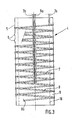
- the ferrule of Figure 3 made from a stainless steel cylinder, comprises two copper helical coils 7 and 8, the two ends are indicated by 7a, 7b and 8a, 8b and constitute an element of use or withdrawal and a pressurizing element respectively. These two coils were obtained from two separate tubes which were wound on the same mandrel, simultaneously or separately, but with the same pitch. In the finished shell, they are arranged one after the other and are housed in the interwall 9 which separates the shell itself from the internal reservoir 10.
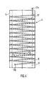
- the ferrule of Figures 4 and 5 is made from a single copper tube 12 whose ends are designated by 12a and 12b which, after brazing was sectioned at two points S 1 and S 2 of one of its turns. Then connected to the two points S 1 and S 2 two straight elements 13 and 14, the ends of which are designated by 13a and 14a respectively. There is thus obtained a coil 12 - 13 for use and a coil 12 - 14 for pressurizing, as in FIG. 3.
- This embodiment has the advantage of simplifying the various manufacturing operations, in particular the winding. It should be noted that the sectioning of the coil at points S 1 and S 2 is preferably carried out after the expansion operation.
- the tube After flattening, the tube is coated, on its external wall, with a layer of tinning product by passage through a bath comprising a mixture of 60% lead and 40% tin.
- the tube is wound on the mandrel according to a helix with a pitch of 80 mm which, of course, corresponds to that of the tinning of the cylinder.
- the tube After extension of the mandrel, the tube is expanded by connecting it to a hydraulic pressurization device which makes a liquid penetrate into it under a pressure of 500 bars.
- the two ends of the coils are fixed to the sheet, preferably by silver brazing, and the entire mandrel is removed. It is then possible, in the case where it is desired to obtain a ferrule of the type shown in FIG. 5, proceed to the connection of the rectilinear elements necessary for this purpose. The ferrule is then placed in a brazing oven to bring it to a temperature of approximately 220 ° C. Finally, the ferrule is rinsed to remove foreign bodies, soldering residues or the like.
- an unreinforced shell having substantially the same dimensional characteristics that is to say the same diameter (508 mm) and the same length (for example 1 m) must, for have an outfit equivalent to buckling and an equivalent impact resistance, be made from a stainless steel sheet of the same type as above but having a thickness of 2.5 mm.
- the brazing material could be deposited on the cylinder and on the tube after the pressurized expansion operation.
- the process can be very simply adapted to the manufacture of any ferrule provided with an internal coil, and even with an external coil. In the latter case, it suffices to wind the copper tube or tubes in a radially contractible hollow mandrel.
Landscapes
- Engineering & Computer Science (AREA)
- Mechanical Engineering (AREA)
- Physics & Mathematics (AREA)
- Thermal Sciences (AREA)
- General Engineering & Computer Science (AREA)
- Shaping Metal By Deep-Drawing, Or The Like (AREA)
- Filling Or Discharging Of Gas Storage Vessels (AREA)
- Pressure Welding/Diffusion-Bonding (AREA)
- Rigid Containers With Two Or More Constituent Elements (AREA)
Applications Claiming Priority (2)
| Application Number | Priority Date | Filing Date | Title |
|---|---|---|---|
| FR8310473A FR2547896B1 (fr) | 1983-06-24 | 1983-06-24 | Procede de fabrication d'une virole pour recipient de stockage de fluide cryogenique et virole ainsi obtenue |
| FR8310473 | 1983-06-24 |
Publications (2)
| Publication Number | Publication Date |
|---|---|
| EP0133384A1 true EP0133384A1 (de) | 1985-02-20 |
| EP0133384B1 EP0133384B1 (de) | 1988-10-12 |
Family
ID=9290143
Family Applications (1)
| Application Number | Title | Priority Date | Filing Date |
|---|---|---|---|
| EP84401285A Expired EP0133384B1 (de) | 1983-06-24 | 1984-06-21 | Verfahren zur Herstellung eines Mantels, insbesondere für Behälter von Tiefsttemperaturflüssigkeit, und so erlangter Mantel |
Country Status (5)
| Country | Link |
|---|---|
| US (1) | US4577386A (de) |
| EP (1) | EP0133384B1 (de) |
| JP (1) | JPS6018223A (de) |
| DE (1) | DE3474526D1 (de) |
| FR (1) | FR2547896B1 (de) |
Cited By (1)
| Publication number | Priority date | Publication date | Assignee | Title |
|---|---|---|---|---|
| EP0430731A1 (de) * | 1989-12-01 | 1991-06-05 | L'air Liquide, Societe Anonyme Pour L'etude Et L'exploitation Des Procedes Georges Claude | Gefäss für kryogene Flüssigkeit |
Families Citing this family (11)
| Publication number | Priority date | Publication date | Assignee | Title |
|---|---|---|---|---|
| US4789028A (en) * | 1984-11-13 | 1988-12-06 | Westinghouse Electric Corp. | Anti-vibration bars for nuclear steam generators |
| US4653576A (en) * | 1985-05-01 | 1987-03-31 | Westinghouse Electric Corp. | Expandable antivibration bar for a steam generator |
| SE457894B (sv) * | 1985-06-17 | 1989-02-06 | Atlas Copco Ab | Saett att stabilisera berg |
| US4720840A (en) * | 1985-06-18 | 1988-01-19 | Westinghouse Electric Corp. | Compliant antivibration bar for a steam generator |
| GB2186431B (en) * | 1986-02-07 | 1989-11-01 | Sperry Sun Inc | Assemblies for supporting electrical circuit boards within tubes |
| US4747373A (en) * | 1986-04-24 | 1988-05-31 | Westinghouse Electric Corp. | Method and apparatus for minimizing antivibration bar gaps of a steam generator |
| US4813117A (en) * | 1986-04-24 | 1989-03-21 | Westinghouse Electric Corp. | Method for making antivibration bar |
| US4963600A (en) * | 1988-12-19 | 1990-10-16 | E. I. Du Pont De Nemours And Company | Chroma neutralization of clear coats by adding pigment dispersions |
| US20140116668A1 (en) * | 2012-10-31 | 2014-05-01 | GM Global Technology Operations LLC | Cooler pipe and method of forming |
| DE102014110718A1 (de) * | 2014-07-29 | 2016-02-04 | Mahle International Gmbh | Wärmeübertrager und Verfahren zur Herstellung des Wärmeübertragers |
| FR3072443B1 (fr) * | 2017-10-12 | 2021-02-19 | Air Liquide | Dispositif de stockage de fluide cryogenique |
Citations (6)
| Publication number | Priority date | Publication date | Assignee | Title |
|---|---|---|---|---|
| FR1246917A (fr) * | 1959-10-16 | 1960-11-25 | Perfectionnements à la fabrication de tuyaux ondulés | |
| US3030780A (en) * | 1958-05-12 | 1962-04-24 | Union Carbide Corp | Refrigerated container for liquefied gases |
| FR1429875A (fr) * | 1965-04-09 | 1966-02-25 | Atomic Energy Authority Uk | Surfaces d'échange de chaleur |
| US3280608A (en) * | 1959-07-28 | 1966-10-25 | Arthur R Parilla | Incremental tube or vessel expander |
| DE2441664A1 (de) * | 1974-08-30 | 1976-03-11 | Interatom | Stroemungswendel und verfahren zu ihrer herstellung |
| US4061184A (en) * | 1976-10-28 | 1977-12-06 | Ebco Manufacturing Company | Heat exchanger for a refrigerated water cooler |
Family Cites Families (3)
| Publication number | Priority date | Publication date | Assignee | Title |
|---|---|---|---|---|
| US3546763A (en) * | 1966-09-01 | 1970-12-15 | Peerless Of America | Heat exchangers and the method of making same |
| US4075264A (en) * | 1976-04-02 | 1978-02-21 | The Dow Chemical Company | Method of insulating a container |
| US4379390A (en) * | 1977-02-28 | 1983-04-12 | Bottum Edward W | Ice-making evaporator |
-
1983
- 1983-06-24 FR FR8310473A patent/FR2547896B1/fr not_active Expired
-
1984
- 1984-06-21 EP EP84401285A patent/EP0133384B1/de not_active Expired
- 1984-06-21 DE DE8484401285T patent/DE3474526D1/de not_active Expired
- 1984-06-25 US US06/625,175 patent/US4577386A/en not_active Expired - Lifetime
- 1984-06-25 JP JP59129428A patent/JPS6018223A/ja active Pending
Patent Citations (6)
| Publication number | Priority date | Publication date | Assignee | Title |
|---|---|---|---|---|
| US3030780A (en) * | 1958-05-12 | 1962-04-24 | Union Carbide Corp | Refrigerated container for liquefied gases |
| US3280608A (en) * | 1959-07-28 | 1966-10-25 | Arthur R Parilla | Incremental tube or vessel expander |
| FR1246917A (fr) * | 1959-10-16 | 1960-11-25 | Perfectionnements à la fabrication de tuyaux ondulés | |
| FR1429875A (fr) * | 1965-04-09 | 1966-02-25 | Atomic Energy Authority Uk | Surfaces d'échange de chaleur |
| DE2441664A1 (de) * | 1974-08-30 | 1976-03-11 | Interatom | Stroemungswendel und verfahren zu ihrer herstellung |
| US4061184A (en) * | 1976-10-28 | 1977-12-06 | Ebco Manufacturing Company | Heat exchanger for a refrigerated water cooler |
Cited By (1)
| Publication number | Priority date | Publication date | Assignee | Title |
|---|---|---|---|---|
| EP0430731A1 (de) * | 1989-12-01 | 1991-06-05 | L'air Liquide, Societe Anonyme Pour L'etude Et L'exploitation Des Procedes Georges Claude | Gefäss für kryogene Flüssigkeit |
Also Published As
| Publication number | Publication date |
|---|---|
| FR2547896B1 (fr) | 1985-11-29 |
| JPS6018223A (ja) | 1985-01-30 |
| DE3474526D1 (en) | 1988-11-17 |
| US4577386A (en) | 1986-03-25 |
| EP0133384B1 (de) | 1988-10-12 |
| FR2547896A1 (fr) | 1984-12-28 |
Similar Documents
| Publication | Publication Date | Title |
|---|---|---|
| EP0133384B1 (de) | Verfahren zur Herstellung eines Mantels, insbesondere für Behälter von Tiefsttemperaturflüssigkeit, und so erlangter Mantel | |
| EP0167418B1 (de) | Doppelwandiges Rohr für Wärmetauscher und dessen Herstellungsverfahren | |
| EP0410884B1 (de) | Dünnwandige metallische Hochdruckflaschen durch eine Aufwicklung auf Kohlenstoffaserbasis verstärkt und Verfahren zur Herstellung | |
| FR2756605A1 (fr) | Conduite flexible a tube interne metallique ondule etanche au gaz | |
| EP0943795B1 (de) | Produktionsweise für einen regenerativen Wärmetauschkreislauf für hohen Wärmefluss, insbesondere für Raketenbrennkammern | |
| FR2526478A1 (fr) | Dispositif de fixation d'extremite d'un filtre de puits, et procede de fabrication de ce dispositif | |
| FR2742368A1 (fr) | Procede de raccordement par soudage heterogene bout a bout de deux pieces de natures differentes et utilisations | |
| EP0156711B1 (de) | Geschweisstes doppelwandiges Rohr, sowie Verfahren zu seiner Herstellung | |
| EP1726676B1 (de) | Verfahren zur Herstellung eines Einbaustücks durch Wicklung von beschichteten Faden und dadurch erhaltenes Einbaustück | |
| FR2599791A1 (fr) | Procede de fixation resistante et etanche d'un element cylindrique creux a l'interieur d'un tube et element cylindrique pour la mise en oeuvre de ce procede | |
| CA1292329C (fr) | Procede de fabrication d'une cuve d'un reacteur nucleaire a eau legere et cuve de reacteur nucleaire fabriquee par ce procede | |
| EP0196971A1 (de) | Wiederherstellungsverfahren durch Verkleidung eines Dampfgeneratorrohres | |
| FR2484875A1 (de) | ||
| EP0227535A1 (de) | Verfahren und Vorrichtung zum Herausziehen eines Rohrabschnittes aus einem Wärmetauscher | |
| FR2918910A1 (fr) | Procede de fabrication d'un element de genie chimique | |
| EP1140386A1 (de) | Verfahren zum verbinden von zwei koaxialen rohren, werkzeug zur herstellung der verbindung und anwendung des verfahrens | |
| FR2544806A1 (fr) | Procede d'assemblage de deux pieces de revolution coaxiales, de meme diametre | |
| FR2863769A1 (fr) | Procede de fabrication d'un filament de cathode d'un tube a rayons x et tube a rayons x | |
| CH508967A (fr) | Procédé de fabrication d'une enceinte étanche | |
| CH502704A (fr) | Procédé de fabrication d'un conducteur éléctrique supra-conducteur renforcé, conducteur électrique renforcé résultant de ce procédé | |
| BE823554A (fr) | Procede de realisation d'elements d'etancheite en polytetrafluoroethylene a effet hydrodynamique | |
| FR2492050A1 (fr) | Procede de fabrication de reservoirs pour fluides sous pression | |
| EP0618400A1 (de) | Metallgefäss für Druckfluide und Verfahren zur Verstärkung solch eines Gefässes | |
| BE473258A (de) | ||
| FR2726885A1 (fr) | Procede de fixation resistante et etanche d'une manchette a l'interieur d'un tube metallique et manchette de reparation d'un tube metallique |
Legal Events
| Date | Code | Title | Description |
|---|---|---|---|
| PUAI | Public reference made under article 153(3) epc to a published international application that has entered the european phase |
Free format text: ORIGINAL CODE: 0009012 |
|
| 17P | Request for examination filed |
Effective date: 19840627 |
|
| AK | Designated contracting states |
Designated state(s): BE DE FR GB IT SE |
|
| 17Q | First examination report despatched |
Effective date: 19860319 |
|
| ITF | It: translation for a ep patent filed | ||
| GRAA | (expected) grant |
Free format text: ORIGINAL CODE: 0009210 |
|
| AK | Designated contracting states |
Kind code of ref document: B1 Designated state(s): BE DE FR GB IT SE |
|
| REF | Corresponds to: |
Ref document number: 3474526 Country of ref document: DE Date of ref document: 19881117 |
|
| GBT | Gb: translation of ep patent filed (gb section 77(6)(a)/1977) | ||
| PLBE | No opposition filed within time limit |
Free format text: ORIGINAL CODE: 0009261 |
|
| STAA | Information on the status of an ep patent application or granted ep patent |
Free format text: STATUS: NO OPPOSITION FILED WITHIN TIME LIMIT |
|
| 26N | No opposition filed | ||
| ITTA | It: last paid annual fee | ||
| EAL | Se: european patent in force in sweden |
Ref document number: 84401285.6 |
|
| PGFP | Annual fee paid to national office [announced via postgrant information from national office to epo] |
Ref country code: SE Payment date: 19970520 Year of fee payment: 14 Ref country code: GB Payment date: 19970520 Year of fee payment: 14 |
|
| PG25 | Lapsed in a contracting state [announced via postgrant information from national office to epo] |
Ref country code: GB Free format text: LAPSE BECAUSE OF NON-PAYMENT OF DUE FEES Effective date: 19980621 |
|
| PG25 | Lapsed in a contracting state [announced via postgrant information from national office to epo] |
Ref country code: SE Free format text: LAPSE BECAUSE OF NON-PAYMENT OF DUE FEES Effective date: 19980622 |
|
| GBPC | Gb: european patent ceased through non-payment of renewal fee |
Effective date: 19980621 |
|
| EUG | Se: european patent has lapsed |
Ref document number: 84401285.6 |
|
| PGFP | Annual fee paid to national office [announced via postgrant information from national office to epo] |
Ref country code: FR Payment date: 20010511 Year of fee payment: 18 |
|
| PGFP | Annual fee paid to national office [announced via postgrant information from national office to epo] |
Ref country code: DE Payment date: 20010523 Year of fee payment: 18 |
|
| PGFP | Annual fee paid to national office [announced via postgrant information from national office to epo] |
Ref country code: BE Payment date: 20010621 Year of fee payment: 18 |
|
| PG25 | Lapsed in a contracting state [announced via postgrant information from national office to epo] |
Ref country code: BE Free format text: LAPSE BECAUSE OF NON-PAYMENT OF DUE FEES Effective date: 20020630 |
|
| BERE | Be: lapsed |
Owner name: L'*AIR LIQUIDE S.A. POUR L'ETUDE ET L'EXPLOITATION Effective date: 20020630 |
|
| PG25 | Lapsed in a contracting state [announced via postgrant information from national office to epo] |
Ref country code: DE Free format text: LAPSE BECAUSE OF NON-PAYMENT OF DUE FEES Effective date: 20030101 |
|
| PG25 | Lapsed in a contracting state [announced via postgrant information from national office to epo] |
Ref country code: FR Free format text: LAPSE BECAUSE OF NON-PAYMENT OF DUE FEES Effective date: 20030228 |
|
| REG | Reference to a national code |
Ref country code: FR Ref legal event code: ST |