EP0133411A1 - Verfahren und Maschinen für das automatische Schweissen oder Schneiden der Verbindung eines Hauptrohres und eines sekundären Abzweigrohres - Google Patents
Verfahren und Maschinen für das automatische Schweissen oder Schneiden der Verbindung eines Hauptrohres und eines sekundären Abzweigrohres Download PDFInfo
- Publication number
- EP0133411A1 EP0133411A1 EP84430022A EP84430022A EP0133411A1 EP 0133411 A1 EP0133411 A1 EP 0133411A1 EP 84430022 A EP84430022 A EP 84430022A EP 84430022 A EP84430022 A EP 84430022A EP 0133411 A1 EP0133411 A1 EP 0133411A1
- Authority
- EP
- European Patent Office
- Prior art keywords
- axis
- welding
- tube
- carriages
- axes
- Prior art date
- Legal status (The legal status is an assumption and is not a legal conclusion. Google has not performed a legal analysis and makes no representation as to the accuracy of the status listed.)
- Granted
Links
Images
Classifications
-
- B—PERFORMING OPERATIONS; TRANSPORTING
- B23—MACHINE TOOLS; METAL-WORKING NOT OTHERWISE PROVIDED FOR
- B23K—SOLDERING OR UNSOLDERING; WELDING; CLADDING OR PLATING BY SOLDERING OR WELDING; CUTTING BY APPLYING HEAT LOCALLY, e.g. FLAME CUTTING; WORKING BY LASER BEAM
- B23K7/00—Cutting, scarfing, or desurfacing by applying flames
- B23K7/005—Machines, apparatus or equipment specially adapted for cutting curved workpieces
- B23K7/006—Machines, apparatus or equipment specially adapted for cutting curved workpieces for tubes
- B23K7/007—Machines, apparatus or equipment specially adapted for cutting curved workpieces for tubes for obtaining tube intersection profiles
-
- B—PERFORMING OPERATIONS; TRANSPORTING
- B23—MACHINE TOOLS; METAL-WORKING NOT OTHERWISE PROVIDED FOR
- B23K—SOLDERING OR UNSOLDERING; WELDING; CLADDING OR PLATING BY SOLDERING OR WELDING; CUTTING BY APPLYING HEAT LOCALLY, e.g. FLAME CUTTING; WORKING BY LASER BEAM
- B23K9/00—Arc welding or cutting
- B23K9/02—Seam welding; Backing means; Inserts
- B23K9/032—Seam welding; Backing means; Inserts for three-dimensional [3D] seams
Definitions
- the subject of the invention is a method and machines for automatically welding or cutting the junction between a main tube and a secondary bypass tube.
- the technical sector is that of the construction of automatic machines or robots for welding or cutting tubular structures comprising junction nodes between tubes.
- the problem to be solved is to automatically carry out the welding between a main tube or a cylindrical shell and a secondary tube which must be welded in derivation on this and this by means of a machine capable of adapting to different geometric parameters. (diameters and thickness of the tubes, angular distance and distance between the axes of the two tubes, position of the junction, length of the tubes) and at different welding parameters (welding speed, shape of the chamfer).
- the weld is distributed substantially symmetrically on either side of the bisector plane and a homogeneous and symmetrical weld bead is obtained.
- many automatic electrical welding methods require the use of a protective flux which can be a flux composed of solid particles. This stream forms a bunch which. must be distributed to cover the weld bead during solidification. To achieve this result and to be able to use a pulverulent flow, the electrodes must be substantially in the bisector plane of the chamfer at the time of welding.
- the invention results in the possibility of automatically welding or cutting the junction between a main tube and a secondary tube placed in bypass thereon by adapting to the geometric dimensions of the tubes and the parameters of the weld.
- the welding machines according to the invention have the advantage that the welding heads work constantly in a vertical position and in the plane of symmetry of the welding chamfer, which makes it possible to use a powder flow and ensures very good quality of the welds. .
- the welding machines according to the invention can be used in all mechanical manufacturing comprising welding work on junctions between cylindrical parts, for example to connect branched tubes to a main tube or to make nodes of tubular structures such as platforms at sea.
- the welding or cutting heads are mounted on a mobile gantry, which can be moved away from the positioning support, it is possible to handle very heavy and bulky parts with lifting devices to place them on the positioning support or to remove them therefrom.
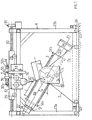
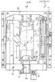
- Figures 1 and 2 show a welding machine intended to automatically weld a junction node between a straight tube or main tube or a cylindrical shell 1 of diameter DI and a secondary tube 2 of diameter D2 which must be welded in bypass on tube 1.
- the axes of the two tubes 1 and 2 can be located in the same plane or not.
- the machine according to the invention is capable of adapting to tubes whose diameters Dl and D2 can take different values as well as to junctions whose angle y between the axes of the two tubes can vary as well as the offset L between the end of the main tube and the bypass.
- It can also be adapted to different welding speeds and to different opening angles of the welding chamfer which vary according to the thickness of the tubes and according to the angular deviation ⁇ .
- Figures 1 and 2 show a junction comprising a single branch, but it is specified that a machine according to the invention can also weld junction nodes comprising several branches. Or several braces. In this case, the machine successively welds each junction.
- a machine according to the invention can be used to automatically weld junction nodes of 4th tubular structures, for example the structures used to build platforms at sea and, in this case, the branches can be welded onto a main tube which is continuous and does not include any cut-out making the two tubes communicate.
- a machine according to the invention can also be used to weld a branch which communicates with a main tube or with a reactor shell or other cylindrical device, and, in this case, the main tube or the shell is cut.
- the machines according to the invention are intended to automatically perform welds on assemblies which can be very heavy and weigh several hundred kilonewtons.
- the essential components of a machine according to the invention are a positioner support 3 which is fixed to the ground and which carries the parts to be welded, a rolling gantry 4 which is placed above the positioner support and which carries a movable assembly of welding or cutting 5 movable along three trirectangular axes and a computer 6 which receives the data which characterize geometrically a junction and the welding, which automatically calculates the coordinates of each point of the intersection of the two tubes and which delivers five set values which are transmitted to five control loops.
- Tubes 1 and 2 are cylinders and. as soon as we know their geometric parameters, that is to say their respective diameters DI and D2, their thicknesses, the angle y of the axes and the longitudinal position L of the branch relative to the main tube and possibly l gap between the two axes if they are not concurrent, the intersection curve of the two tubes is defined and it is therefore possible to program a computer so that it calculates the coordinates of the different points of the curve from the geometric parameters which are data entered into the computer by means of a keyboard or any other means of entering data.
- the geometric parameters can be measured by sensors which are connected to the computer by an interface circuit allowing the computer to directly enter the geometric parameters.
- the computer can periodically deliver digital data corresponding for example to the coordinates, measured along three perpendicular axes, of the successive points of the intersection.
- the welding head can be moved along these three axes, it could theoretically be envisaged to leave the part to be welded fixed and to automatically move one or more welding heads so that they automatically follow the intersection curve at the desired speed.
- the object of the invention is to provide a welding machine in which the welding is constantly carried out flat, that is to say by means of electrodes which are placed vertically above the welding chamfer and, more, keeping the electrodes substantially in the bisector plane of the weld chamfer so that the weld beads are regular and homogeneous.
- This result is achieved by moving the welding head along three trirectangular axes and by simultaneously rotating the junction during welding around two perpendicular axes, one of which coincides with the axis of the main tube.
- FIG. 2 represents a plan view and partially in section of the positioning frame which supports the parts to be welded and which makes it possible to orient them automatically.
- This frame comprises longitudinal members 3a, 3b which are fixed to the ground, which are interconnected by crosspieces and which support two cheeks or lateral flanges 3c, 3d, of generally triangular shape and located in two parallel planes.
- Each cheek carries, at its apex, a level, respectively 7a, 7b.
- the two bearings define a horizontal transverse axis Y Y1.
- the positioner frame comprises a tilting frame 8, which comprises an open U-shaped frame composed of a cross member 8a, parallel to the axis Y Y1 and two lateral branches 8b, 8c. Each lateral branch carries, on the external side, a pin 9a, 9b. These. pins are supported by bearings 7a, 7b in which they can pivot freely, so that the frame 8 can tilt around the transverse axis Y Y1.
- One of the pins for example the pin 9a, carries a rotary drive device constituted for example by a drive pinion 10 which is driven in rotation, for example by a geared motor or servomotor 11 of the toothed wheel type. auger, fitted with a hydraulic motor.
- the servomotor 11 is associated with a control loop which comprises an angular displacement sensor, of any known type, for example an analog sensor of the synchro or potentiometer type, or a digital pulse sensor. This sensor measures the angle of rotation ⁇ of the frame 8 around the axis Y Y1.
- the control loop includes comparison means which compare the measured value of the angle ⁇ to a set value ⁇ o and which control the servomotor in the direction which brings the gap ⁇ - ⁇ o to zero.
- the two pins 9a, 9b can each be driven by a servomotor associated with a control loop and the two loops receive the same set value ⁇ o.
- the tilting frame 8 further comprises a movable transverse beam 8d which is parallel to the crosspiece 8a.
- the movable beam 8d On the beam 8d are fixed the rods 12 of two hydraulic cylinders 13 which are housed inside the lateral branches 8b, 8c which are hollow.
- the movable beam 8d carries two guide sleeves 13a, 13b which engage inside the hollow branches 8b and 8c and which support the beam.
- the positioner frame comprises, in addition, two centering cones 14a, 14b which engage in the ends of the main tube 1 as shown in Figure 2.
- One of the cones 14a is supported by a shaft end 15 which is itself mounted on bearings 16 carried by the cross member 8a. These bearings can be replaced by bearings.
- the end of the shaft 15 carries a drive pinion 17 which cooperates with a drive servomotor 18.
- the servomotor 18 is of the same type as the servomotor 11 and it is also associated with a servo loop comprising an angular displacement sensor which measures the angle a of pivoting of the cone 14a around the longitudinal axis X X1 of the tree 15.
- the longitudinal axis X XI is perpendicular to the transverse axis Y YI and situated substantially in the longitudinal plane of symmetry of the frame 8.
- the control loop maintains the angle a equal to a setpoint ao.
- the cone 14b is carried by a shaft end 19 which is supported by bearings 20 carried by the beam 8d so that the cone 14b and the shaft 19 can pivot freely.
- the shafts 15 and 19 and the cones 14a, 14b are aligned along the axis X X1.
- the jacks 13 make it possible to move the beam 8d parallel to the longitudinal axis X X1 to release the part to be welded or to keep the cone 14b engaged in one end of the main tube 1.
- the chambers of the cylinders of the jacks 13 situated on the side of the beam 8d, are connected to a hydropneumatic accumulator 22, which acts as a spring and which exerts on the rods 12 a constant traction which keeps the tube 1 clamped between the two cones 14a, 14b while allowing dilation.
- the hydropneumatic tank can be replaced by equivalent elastic means.
- the friction between the cones 14a, 14b and the ends of the tube 1 may be sufficient for the rotational movement due to the servomotor 18 to drive the tube 1 and the cone 14b in rotation about the axis X XI.
- the cone 14a advantageously carries a drive finger 21a and a drive member 21b having the form of a lever or a fork is fixed to the periphery of the tube 1.
- the finger 21a is supported on the member 21b and drives the tube 1 in rotation.
- the end of the tube end 2 is chamfered according to a determined law, then the branch 2 is positioned on the tube 1 and it is fixed thereon for example by welding points.
- the tube 1 carrying the branch 2 is then placed between the conical jaws 14a and 14b.
- the internal diameter of the tube 1 exactly determines the position of the end of the tube on the conical jaw 14a and the computer can calculate this position which can be used as the origin for the longitudinal coordinates.
- the conical shape of the jaws centers the tube 1 on the X XI axis
- FIG. 1 shows in elevation the traveling gantry 4 which carries the mobile welding or cutting assembly 5.
- the gantry 4 has a rigid structure which spans the positioner frame. This structure is composed of vertical uprights 23a, 23b, the bases of which are connected together by longitudinal beams 24 and the vertices of which are connected together by beams and spacers forming a rigid frame.
- the gantry 4 is mounted on wheels or rollers 25 which roll on a longitudinal raceway constituted by rails or slides fixed to the ground, which makes it possible to move the gantry to release the positioning frame, in order to carry out the handling operations for the installation of the part to be welded on the frame and for removal after welding. Stops make it possible to precisely fix the relative position of the gantry 4 relative to the frame.
- a locking device 26 for example screw jacks or pins or any other equivalent means, makes it possible to block the gantry on the raceway in its working position.
- the gantry 4 carries at the upper part a longitudinal raceway 27. constituted by beams, rails, slides, etc., horizontal and parallel to the vertical plane passing through the axis X X1.
- the mobile welding or cutting assembly 5 comprises a first carriage 28 fitted with rollers or wheels 29 which roll on the raceway 27.
- the carriage 28 is equipped with a servomotor which makes it possible to move it longitudinally on the raceway 27.
- the carriage 28 is secured to a nut which is mounted on a micrometric screw 30 parallel to the rails 27 and this screw is rotated by a gear motor unit 31.
- An analog or digital sensor measures the linear displacements x of the carriage 28 and transmits the measurement to a servo loop which compares it to a set value xo and which automatically controls the servomotor to cancel the deviation x - xo.
- the micrometric screw and nut device can be replaced by a linear displacement cylinder or by any other equivalent servomotor.
- the carriage 28 carries a horizontal transverse raceway parallel to the axis Y Y1, which is constituted for example by two slides 32a, 32b.
- the mobile assembly comprises a second carriage 33 equipped with rollers 34 which roll in the slides 32a and 32b.
- the carriage 33 is driven in translation parallel to the Y axis Y1 by a servomotor 35 identical or not to the servomotor 31 and also comprising a servo loop which receives a reference value yo and which maintains the positioning y of the carriage 33 measured according to a Y axis Y1 equal to the set value.
- the carriage 33 carries a vertical raceway constituted for example by one or more vertical rails 36.
- the mobile assembly comprises a third carriage 37 equipped with wheels or rollers 38 which roll along the vertical rails 36.
- the carriage 37 is moved vertically by a servomotor 39 carried by the carriage 33 which is of the same type or not as the servomotors 31 and 35 and which also includes a servo loop which maintains the height z of the welding or cutting heads 40 equal to one setpoint zo.
- the carriage 37 carries one or more welding or cutting heads 40 of any known type.
- the welding heads are fixed to the carriage 37, so that the electrodes are vertical and remain vertical during all movements.
- Each welding or cutting head comprises the usual devices for driving from electrodes, a gas or powder flow, supply of electric current, etc.
- the objective of the present invention is to orient the piece to be welded at the same time as the welding or cutting heads are cut, so that the welding or cutting electrodes remain vertical and are in the bisector plane of the welding chamfer.
- the welding heads can be connected to the carriage 37 by a rotary support around a vertical axis which optimizes the relative position of a head relative to the other, depending on their distance and the shape of the chamfer so that each electrode is: substantially in the bisecting plane of the chamfer located directly above it this.
- FIGS 1 and 2 show the essential mechanical components of an automatic welding machine according to the invention.
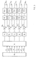
- FIG. 3 is a diagram of the calculation and servo control members.
- the machine comprises a computer 6 which is associated with data entry members, for example a console 6a, which makes it possible to introduce into the memory of the calculation unit, the parameters of the welding to be carried out.
- These parameters are the diameter Dl of the main tube 1, the diameter D2 at the end of the branch tube 2, the angle y that the axis of the derivation makes with the axis X Xl of the main tube, the distance L between the end of the main tube and the point of the branch closest to it, the thicknesses el and e2 of the two tubes and one or more parameters ch which characterize the law. variation of the chamfer.
- the desired welding speed V is also entered into the memory. In the case where the axes of the two tubes are not concurrent, the distance between these axes is also introduced.
- the computer is programmed to calculate, from this data, five variables which are transmitted as set values to the five comparators of the five control loops which have just been described.
- the program is established so that the electrodes move along the welding chamfer at the desired welding speed and so that, at the same time, the assembly to be welded is oriented by pivoting around the axes X Xl and Y Y1, such so that the bisector plane of the chamfer situated below each electrode is substantially vertical so that the electrode is situated substantially in this plane.
- the welding head has two offset electrodes which weld simultaneously; we have previously seen that they can be mounted on a rotary support around a vertical axis which makes it possible to optimize the relative position of the two electrodes relative to one another.
- FIG. 3 represents the five outputs of the computer 6 and the five reference values which are emitted periodically by the latter.
- the first output line gives the set value of the pivot angle ao of the tilting frame 8 around the axis X XI.
- the first line shows the servomotor 18 which drives the frame 8 and a servo loop 18a comprising a sensor 18b which measures the angle of rotation a and which transmits the measured value to a comparator 18c which compares it to the set value ao sent by the computer.
- the other lines of FIG. 3 represent respectively the set values ⁇ o, xo, yo, zo emitted by the computer and the control loops 11a, 31a, 35a, 39a associated with each of them comprising the sensors Ilb, 31b , 35b, 39b and the comparators 11c, 31c, 35c, 39c.
- ⁇ is the pivot angle around the Y axis Y1 and x
- y and z are the displacements of the movable assembly along three trirectangular axes, the yl axis preferably being parallel to the Y axis Y1, the x x1 axis being a horizontal axis, preferably longitudinal and z zl being necessarily vertical.
- the piece to be welded and the mobile assembly are placed manually in a determined position which is taken into account in the program, for example in the position shown in FIG. 1 or the electrode 40 is placed above point A of the weld, which is located at the intersection of the generatrices which are in the longitudinal plane of symmetry and which form an obtuse angle between them.
- the part to be welded is positioned so that the bisector plane of the welding chamfer at point A is substantially vertical.
- the computer controls the operations and the welding is carried out automatically.
- each of the set values can be adjusted manually by an operator, from a control console, which makes it possible to manually control all the operations of approaching the welding head and initial orientation. of the part to be welded.
- the maneuvers of the gantry crane to clear the frame are controlled from the console.
- welding heads can be replaced by cutting means, for example by an oxy-cutting torch and in this case the machine described can automatically cut a tube.
- the cone 14a which is driven in rotation, is fitted. a jaw which grips the other end of the tube and which keeps it cantilevered under the cutting head.
Landscapes
- Engineering & Computer Science (AREA)
- Mechanical Engineering (AREA)
- Physics & Mathematics (AREA)
- Plasma & Fusion (AREA)
- Butt Welding And Welding Of Specific Article (AREA)
- Lining Or Joining Of Plastics Or The Like (AREA)
- Branch Pipes, Bends, And The Like (AREA)
Priority Applications (1)
| Application Number | Priority Date | Filing Date | Title |
|---|---|---|---|
| AT84430022T ATE36981T1 (de) | 1983-07-22 | 1984-06-25 | Verfahren und maschinen fuer das automatische schweissen oder schneiden der verbindung eines hauptrohres und eines sekundaeren abzweigrohres. |
Applications Claiming Priority (2)
| Application Number | Priority Date | Filing Date | Title |
|---|---|---|---|
| FR8312307 | 1983-07-22 | ||
| FR8312307A FR2549406B1 (fr) | 1983-07-22 | 1983-07-22 | Procede et machines pour souder ou decouper automatiquement la jonction entre un tube principal et un tube secondaire en derivation |
Publications (2)
| Publication Number | Publication Date |
|---|---|
| EP0133411A1 true EP0133411A1 (de) | 1985-02-20 |
| EP0133411B1 EP0133411B1 (de) | 1988-09-07 |
Family
ID=9291108
Family Applications (1)
| Application Number | Title | Priority Date | Filing Date |
|---|---|---|---|
| EP84430022A Expired EP0133411B1 (de) | 1983-07-22 | 1984-06-25 | Verfahren und Maschinen für das automatische Schweissen oder Schneiden der Verbindung eines Hauptrohres und eines sekundären Abzweigrohres |
Country Status (6)
| Country | Link |
|---|---|
| US (1) | US4659903A (de) |
| EP (1) | EP0133411B1 (de) |
| JP (1) | JPS6044182A (de) |
| AT (1) | ATE36981T1 (de) |
| DE (1) | DE3473843D1 (de) |
| FR (1) | FR2549406B1 (de) |
Cited By (3)
| Publication number | Priority date | Publication date | Assignee | Title |
|---|---|---|---|---|
| FR2591516A1 (fr) * | 1985-12-13 | 1987-06-19 | Havre Chantiers | Machines a decouper automatiquement l'intersection d'un tube avec un ou plusieurs tubes et/ou un ou plusieurs plans |
| DE102015206044A1 (de) | 2015-04-02 | 2016-10-06 | Fraunhofer-Gesellschaft zur Förderung der angewandten Forschung e.V. | Schweißanordnung zum dauerhaften Fügen eines ersten rohrförmigen Bauteils mit einem zweiten Bauteil |
| FR3137431A1 (fr) * | 2022-06-30 | 2024-01-05 | Naval Group | Procédé de piquage de tubes |
Families Citing this family (22)
| Publication number | Priority date | Publication date | Assignee | Title |
|---|---|---|---|---|
| DE3818402C1 (de) * | 1988-05-31 | 1989-11-16 | Kloeckner-Wilhelmsburger Gmbh, 2054 Geesthacht, De | |
| JPH0710998Y2 (ja) * | 1988-11-30 | 1995-03-15 | 富士機工株式会社 | ステアリングコラム装置 |
| US4937427A (en) * | 1989-03-23 | 1990-06-26 | Mcvicker Noel | Apparatus and method for automatically welding a T-junction connector to a main pipe |
| EP0476501B1 (de) * | 1990-09-17 | 1996-12-18 | Hitachi, Ltd. | Metallbehälter mit Stamm- und Zweigrohr und sein Herstellungsverfahren. |
| US6964798B2 (en) | 1993-11-16 | 2005-11-15 | Baxter International Inc. | Multi-layered polymer based thin film structure for medical grade products |
| US6590033B2 (en) | 1999-09-09 | 2003-07-08 | Baxter International Inc. | Cycloolefin blends and method for solvent bonding polyolefins |
| US6335508B1 (en) * | 2000-05-25 | 2002-01-01 | Kyong H. Nam | Pipe handling system for laser and other pipe treating processes |
| WO2005008726A2 (en) * | 2003-07-09 | 2005-01-27 | Newport Corporation | Flip chip device assembly machine |
| MXPA06011837A (es) | 2004-04-27 | 2007-01-16 | Baxter Int | Sistema de reactor de tanque agitado. |
| US20080217377A1 (en) * | 2007-03-06 | 2008-09-11 | Alcoa Inc. | Fracture Resistant Friction Stir Welding Tool |
| US7793816B2 (en) * | 2007-09-07 | 2010-09-14 | Alcoa Inc. | Friction stir welding apparatus |
| US7854362B2 (en) | 2008-03-14 | 2010-12-21 | Alcoa Inc. | Advanced multi-shouldered fixed bobbin tools for simultaneous friction stir welding of multiple parallel walls between parts |
| EP2140967A1 (de) * | 2008-07-03 | 2010-01-06 | Hendricks Industries ApS | Verfahren zum Schweissen eines aus metallischen Blechen hergestellten Halbproduktes und eine Anordnung zum Tragen und Drehen eines aus metallischen Blechen hergestellten Halbproduktes |
| FR2937257A1 (fr) * | 2008-10-21 | 2010-04-23 | Air Liquide | Methode de construction applicable aux adsorbeurs radiaux de grosse taille |
| CN101664845B (zh) * | 2009-10-12 | 2011-04-06 | 上海交通大学 | 海洋石油平台多几何体相贯钢结构数控切割系统 |
| US8210418B1 (en) * | 2011-06-09 | 2012-07-03 | Landoll Corporation | Multi-station, gantry-based automated welding system |
| US8434657B2 (en) | 2011-06-09 | 2013-05-07 | Landoll Corporation | Gantry-based welding system and method |
| EP2821176A1 (de) * | 2013-07-02 | 2015-01-07 | Siemens VAI Metals Technologies GmbH | Vorrichtung zum Verschieben einer Anordnung zum Schneiden und Schweißen von Metallbändern ; Verfahren zum Schneiden und Schweissen unter Verwendung solcher Vorrichtung |
| US10556290B2 (en) * | 2015-11-20 | 2020-02-11 | Fanuc Robotics America Corporation | System for coordinated stationary tracking with root path memory clocking for cylindrical welding |
| US10493544B2 (en) * | 2016-02-05 | 2019-12-03 | Textron Innovations, Inc. | System and method for cutting composite materials |
| CN116713663B (zh) * | 2023-04-28 | 2025-09-30 | 成都阿朗科技有限责任公司 | 一种回转装置、岔管焊接设备及岔管焊接方法 |
| CN118663972B (zh) * | 2024-08-23 | 2024-11-22 | 运城学院 | 一种弯曲管道切割机构及其使用方法 |
Citations (4)
| Publication number | Priority date | Publication date | Assignee | Title |
|---|---|---|---|---|
| DE2713541A1 (de) * | 1977-03-28 | 1978-10-05 | Esab Kebe Gmbh | Vorrichtung zum steuern von bewegungen an einer rohrbrennschneidmaschine |
| DE3005153A1 (de) * | 1980-02-08 | 1981-08-13 | Mannesmann AG, 4000 Düsseldorf | Verfahren zum anschweissen von abzweigstutzen an rohre oder zylindrische behaelter |
| US4349182A (en) * | 1975-11-13 | 1982-09-14 | Vernon Tool Company Ltd. | Tape-controlled metal cutting apparatus |
| US4384901A (en) * | 1981-12-22 | 1983-05-24 | Lame, Inc. | Method and apparatus for cutting and beveling pipe |
Family Cites Families (6)
| Publication number | Priority date | Publication date | Assignee | Title |
|---|---|---|---|---|
| US3243094A (en) * | 1964-11-13 | 1966-03-29 | Southwest Welding & Mfg | Welding fixture |
| JPS5120342B2 (de) * | 1972-06-01 | 1976-06-24 | ||
| FR2278450A1 (fr) * | 1974-02-22 | 1976-02-13 | Shin Meiwa Ind Co Ltd | Appareil automatique a souder |
| US4233491A (en) * | 1978-06-26 | 1980-11-11 | Shin Meiwa Industry Co., Ltd. | Method and apparatus for controlling increment type position control apparatus |
| JPS5545563A (en) * | 1978-09-26 | 1980-03-31 | Shin Meiwa Ind Co Ltd | Welding robot with fusing instrument |
| US4264058A (en) * | 1980-01-17 | 1981-04-28 | Wear Charles W | Truck bolster ring renewal system |
-
1983
- 1983-07-22 FR FR8312307A patent/FR2549406B1/fr not_active Expired
-
1984
- 1984-06-25 EP EP84430022A patent/EP0133411B1/de not_active Expired
- 1984-06-25 DE DE8484430022T patent/DE3473843D1/de not_active Expired
- 1984-06-25 AT AT84430022T patent/ATE36981T1/de active
- 1984-06-28 US US06/625,451 patent/US4659903A/en not_active Expired - Fee Related
- 1984-07-19 JP JP59148696A patent/JPS6044182A/ja active Pending
Patent Citations (4)
| Publication number | Priority date | Publication date | Assignee | Title |
|---|---|---|---|---|
| US4349182A (en) * | 1975-11-13 | 1982-09-14 | Vernon Tool Company Ltd. | Tape-controlled metal cutting apparatus |
| DE2713541A1 (de) * | 1977-03-28 | 1978-10-05 | Esab Kebe Gmbh | Vorrichtung zum steuern von bewegungen an einer rohrbrennschneidmaschine |
| DE3005153A1 (de) * | 1980-02-08 | 1981-08-13 | Mannesmann AG, 4000 Düsseldorf | Verfahren zum anschweissen von abzweigstutzen an rohre oder zylindrische behaelter |
| US4384901A (en) * | 1981-12-22 | 1983-05-24 | Lame, Inc. | Method and apparatus for cutting and beveling pipe |
Cited By (5)
| Publication number | Priority date | Publication date | Assignee | Title |
|---|---|---|---|---|
| FR2591516A1 (fr) * | 1985-12-13 | 1987-06-19 | Havre Chantiers | Machines a decouper automatiquement l'intersection d'un tube avec un ou plusieurs tubes et/ou un ou plusieurs plans |
| DE102015206044A1 (de) | 2015-04-02 | 2016-10-06 | Fraunhofer-Gesellschaft zur Förderung der angewandten Forschung e.V. | Schweißanordnung zum dauerhaften Fügen eines ersten rohrförmigen Bauteils mit einem zweiten Bauteil |
| WO2016156039A1 (de) | 2015-04-02 | 2016-10-06 | Fraunhofer-Gesellschaft zur Förderung der angewandten Forschung e. V. | SCHWEIßANORDNUNG ZUM DAUERHAFTEN FÜGEN EINES ERSTEN ROHRFÖRMIGEN BAUTEILS MIT EINEM ZWEITEN BAUTEIL |
| US10646967B2 (en) | 2015-04-02 | 2020-05-12 | Fraunhofer-Gesellschaft Zur Foerderung Der Angewandten Forschung E.V. | Welding assembly for permanent joining of a first tubular component with a second component |
| FR3137431A1 (fr) * | 2022-06-30 | 2024-01-05 | Naval Group | Procédé de piquage de tubes |
Also Published As
| Publication number | Publication date |
|---|---|
| FR2549406A1 (fr) | 1985-01-25 |
| ATE36981T1 (de) | 1988-09-15 |
| EP0133411B1 (de) | 1988-09-07 |
| US4659903A (en) | 1987-04-21 |
| JPS6044182A (ja) | 1985-03-09 |
| FR2549406B1 (fr) | 1986-12-26 |
| DE3473843D1 (en) | 1988-10-13 |
Similar Documents
| Publication | Publication Date | Title |
|---|---|---|
| EP0133411B1 (de) | Verfahren und Maschinen für das automatische Schweissen oder Schneiden der Verbindung eines Hauptrohres und eines sekundären Abzweigrohres | |
| CA2145340C (fr) | Installation de soudage automatique | |
| CA2002513C (fr) | Methode et dispositif de detection automatique du profil d'une surface et en vue d'effectuer un travail | |
| EP3628599A1 (de) | Verfahren, werkzeug und anlage zur herstellung von rumpfabschnitten eines luftfahrzeugs | |
| EP0611217B1 (de) | Automatische ''in situ'' Schweissmaschine zum Folgen von gekrümmten Konturen, und mit einer Programmiersteuerung zum Extrapolieren | |
| WO1996041697A1 (fr) | Installation pour travailler une zone d'un tube au moyen d'un faisceau laser et application aux tubes d'une canalisation sur une barge de pose en mer ou de recuperation de cette canalisation | |
| FR2488973A1 (fr) | Procede et dispositif d'intervention sur une conduite sous-marine | |
| FR2539659A1 (fr) | Appareil-manipulateur avec un faisceau de lumiere laser | |
| FR2541920A1 (fr) | Manipulateur a bras telescopique | |
| FR2568799A1 (fr) | Centre d'usinage de profiles a commande numerique | |
| EP0735190A1 (de) | Verfahren zum Schrauben und Losschrauben der Schienenschrauben eines Gleises und Vorrichtung zur Durchführung des Verfahrens | |
| FR2578773A1 (fr) | Robot multitaches pour le traitement des parois internes de cuves ou de capacites | |
| WO2016005701A2 (fr) | Procede de forage d'un sol a l'aide d'un bras robotise | |
| FR2591516A1 (fr) | Machines a decouper automatiquement l'intersection d'un tube avec un ou plusieurs tubes et/ou un ou plusieurs plans | |
| EP3599062A1 (de) | Schweissroboter | |
| EP0320378A1 (de) | Verfahren und Vorrichtung zum Spritzen eines Produkts auf die entgegengesetzten Seiten einer Platte | |
| CA2630910C (fr) | Dispositif de soudage automatique du type mig/mag | |
| EP0593361B1 (de) | Verfahren und Vorrichtung zum Schleifen zweier stumpf aneinanderstossender Schienen | |
| FR2554037A1 (fr) | Dispositif pour effectuer un travail sur une structure a plusieurs branches | |
| FR2704166A1 (fr) | Procédé et dispositif pour effectuer le soudage de tronçons de tube à l'aide de rayons laser. | |
| EP3414040B1 (de) | Vorrichtung zum automatischen verschweissen einer naht, insbesondere einer v-naht | |
| FR3145106A1 (fr) | Système de soudage à l’arc | |
| EP1775072A1 (de) | Einrichtung zum Greifen und Handhaben von zylindrischen Teilen, Montageanlage mit einer solchen Einrichtung und assoziiertes Montageverfahren | |
| FR2476059A1 (fr) | Machine et procede pour conformer le bord d'une plaque de verre | |
| FR2743734A1 (fr) | Machine d'application d'un revetement sur une piece par pulverisation cycloidale |
Legal Events
| Date | Code | Title | Description |
|---|---|---|---|
| PUAI | Public reference made under article 153(3) epc to a published international application that has entered the european phase |
Free format text: ORIGINAL CODE: 0009012 |
|
| AK | Designated contracting states |
Designated state(s): AT BE CH DE GB IT LI LU NL SE |
|
| 17P | Request for examination filed |
Effective date: 19850328 |
|
| 17Q | First examination report despatched |
Effective date: 19860327 |
|
| RAP1 | Party data changed (applicant data changed or rights of an application transferred) |
Owner name: SOCIETE NOUVELLE DES ATELIERS ET CHANTIERS DU HAVR |
|
| D17Q | First examination report despatched (deleted) | ||
| GRAA | (expected) grant |
Free format text: ORIGINAL CODE: 0009210 |
|
| AK | Designated contracting states |
Kind code of ref document: B1 Designated state(s): AT BE CH DE GB IT LI LU NL SE |
|
| REF | Corresponds to: |
Ref document number: 36981 Country of ref document: AT Date of ref document: 19880915 Kind code of ref document: T |
|
| REF | Corresponds to: |
Ref document number: 3473843 Country of ref document: DE Date of ref document: 19881013 |
|
| GBT | Gb: translation of ep patent filed (gb section 77(6)(a)/1977) | ||
| ITF | It: translation for a ep patent filed | ||
| PLBE | No opposition filed within time limit |
Free format text: ORIGINAL CODE: 0009261 |
|
| STAA | Information on the status of an ep patent application or granted ep patent |
Free format text: STATUS: NO OPPOSITION FILED WITHIN TIME LIMIT |
|
| 26N | No opposition filed | ||
| PGFP | Annual fee paid to national office [announced via postgrant information from national office to epo] |
Ref country code: AT Payment date: 19910528 Year of fee payment: 8 |
|
| PGFP | Annual fee paid to national office [announced via postgrant information from national office to epo] |
Ref country code: CH Payment date: 19910610 Year of fee payment: 8 |
|
| PGFP | Annual fee paid to national office [announced via postgrant information from national office to epo] |
Ref country code: GB Payment date: 19910618 Year of fee payment: 8 |
|
| PGFP | Annual fee paid to national office [announced via postgrant information from national office to epo] |
Ref country code: SE Payment date: 19910619 Year of fee payment: 8 |
|
| PGFP | Annual fee paid to national office [announced via postgrant information from national office to epo] |
Ref country code: DE Payment date: 19910620 Year of fee payment: 8 |
|
| PGFP | Annual fee paid to national office [announced via postgrant information from national office to epo] |
Ref country code: LU Payment date: 19910621 Year of fee payment: 8 |
|
| ITTA | It: last paid annual fee | ||
| PGFP | Annual fee paid to national office [announced via postgrant information from national office to epo] |
Ref country code: NL Payment date: 19910630 Year of fee payment: 8 |
|
| PGFP | Annual fee paid to national office [announced via postgrant information from national office to epo] |
Ref country code: BE Payment date: 19910715 Year of fee payment: 8 |
|
| EPTA | Lu: last paid annual fee | ||
| PG25 | Lapsed in a contracting state [announced via postgrant information from national office to epo] |
Ref country code: LU Free format text: LAPSE BECAUSE OF NON-PAYMENT OF DUE FEES Effective date: 19920625 Ref country code: GB Effective date: 19920625 Ref country code: AT Effective date: 19920625 |
|
| PG25 | Lapsed in a contracting state [announced via postgrant information from national office to epo] |
Ref country code: SE Effective date: 19920626 |
|
| PG25 | Lapsed in a contracting state [announced via postgrant information from national office to epo] |
Ref country code: LI Effective date: 19920630 Ref country code: CH Effective date: 19920630 Ref country code: BE Effective date: 19920630 |
|
| BERE | Be: lapsed |
Owner name: SOC. NOUVELLE DES ATELIERS ET CHANTIERS DU HAVRE Effective date: 19920630 |
|
| PG25 | Lapsed in a contracting state [announced via postgrant information from national office to epo] |
Ref country code: NL Effective date: 19930101 |
|
| NLV4 | Nl: lapsed or anulled due to non-payment of the annual fee | ||
| GBPC | Gb: european patent ceased through non-payment of renewal fee |
Effective date: 19920625 |
|
| REG | Reference to a national code |
Ref country code: CH Ref legal event code: PL |
|
| PG25 | Lapsed in a contracting state [announced via postgrant information from national office to epo] |
Ref country code: DE Effective date: 19930302 |
|
| EUG | Se: european patent has lapsed |
Ref document number: 84430022.8 Effective date: 19930109 |